How was the NES graphics arranged?
Launched in 1983, the Nintendo Entertainment System (NES) home console was a cheap but powerful machine that achieved phenomenal success. Using the Picture Processing Unit (PPU), the system could create quite impressive graphics for those times, which even today looks quite good in the right context. The most important aspect was memory efficiency - when creating graphics, we had to manage with as few bytes as possible. However, along with this, NES provided developers with powerful and easy-to-use features that allowed it to stand out from older home consoles. Having understood the principles of creating NES graphics, you can feel the technical perfection of the system and realize how much easier it is for modern game developers to work.
NES background graphics were assembled from four separate components, a combination of which formed the image that we see on the screen. Each component was responsible for a separate aspect; color, layout, raw pixel graphics, etc. Such a system may seem unnecessarily complex and cumbersome, but in the end it used memory much more efficiently and allowed creating simple effects in a small amount of code. If you want to understand NES graphics, then these four components will be key information.
This article assumes that you are familiar with computer mathematics, and in particular with the fact that 8 bits = 1 byte, and 8 bits can represent 256 values. An understanding of how the hexadecimal notation works is also necessary. But even without this technical knowledge, the article may seem interesting.
Short review
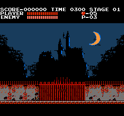
Above is an image from the first scene of Castlevania (1986): the gate leading to the castle where the game will take place. This image is 256 × 240 pixels in size and uses 10 different colors. To describe this image in memory, we must take advantage of the limited color palette, and save space by storing only a minimal amount of information. One of the naive approaches is to use an indexed palette in which each pixel has a volume of 4 bits, that is, 2 pixels are placed in a byte. This will require 256 * 240/2 = 30720 bytes, but as we will soon see, NES can cope with this task much more efficiently.
The main concepts in the NES graphics theme are tiles and blocks [1]. A tile is an area of 8 × 8 pixels, and a block is an area of 16 × 16 pixels, and each of them is tied to a grid with the same cell size. After adding these grids, we can see the structure of the graphics. Here is the entrance to the castle with a grid at double magnification.
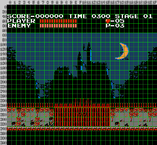
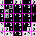
In this grid, blocks are shown in light green, and tiles in dark green. Rulers along the axes have hexadecimal values that can be added to find a position; for example, the heart in the status bar is at $ 15 + $ 60 = $ 75, which in decimal is 117. Each screen contains 16 × 15 blocks (240) and 32 × 30 tiles (960). Now let's see how this image is described and start with the raw pixel graphics.
CHR
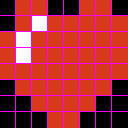
The CHR structure describes “raw” pixel graphics without its color and position, and is set in tiles. The entire memory page contains 256 CHR tiles, and each tile has a depth of 2 bits. Here are the heart graphics:
And here is how it is described in CHR [2]:
Such a description takes 2 bits per pixel, that is, with a size of 8 × 8 it turns out 8 * 8 * 2 = 128 bits = 16 bytes. Then the whole page takes 16 * 256 = 4096 bytes. Here are all the CHRs used in the image from Castlevania.
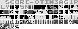
Recall that filling out an image requires 960 tiles, but CHR only allows 256. This means that most tiles are repeated, on average, 3.75 times, but more often only a small number of them are used (for example, empty background, single-color tiles or repeating patterns). The image from Castlevania uses a lot of empty tiles, as well as solid blue. To see how tiles are assigned, we use nametables.
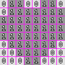
NAMETABLE
The name table assigns a CHR file to each position on the screen, and there are 960 in total. Each position is specified in one byte, that is, the entire name table takes up to 960 bytes. Tiles are assigned in order from left to right, from top to bottom, and correspond to the calculated position found by adding the values from the rulers shown above. That is, the position in the upper left corner is $ 0, to the right of it is $ 1, and below it is $ 20.
The values in the nametable depend on the order in which the CHR is populated. Here is one of the options [3]:
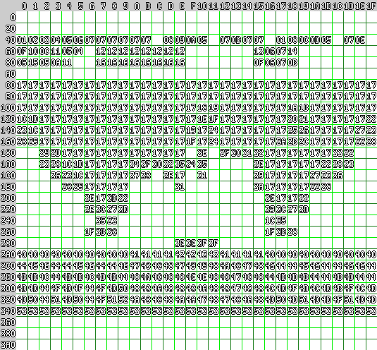
In this case, the heart (at position $ 75) has a value of $ 13.
Next, to add color, we need to select a palette.
Palette
NES has a system palette of 64 colors [4], and from it we select the palettes that will be used in rendering. Each palette contains 3 unique colors plus the overall background color. The image has a maximum of 4 palettes, which in total occupy 16 bytes. Here are the palettes for the image from Castlevania:
Palettes cannot be used arbitrarily. Only one palette is applied per block. It is because of this need to separate each 16 × 16 area according to the color palette of the game for NES have such a “block” look. Masterfully executed graphics, for example, from the Castlevania screensaver, can be avoided by mixing colors at the edges of the blocks, which hides the presence of a grid.
The selection of a palette for each block is performed using the last component - attributes.
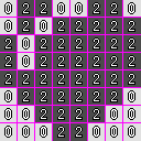
Attributes
Attributes occupy 2 bits per block. They determine which of the 4 palettes to use. This image shows which palettes defined by the attributes use different blocks [5]:
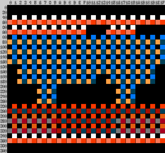
As you can see, the palettes are divided into sections, but this is tricky due to the use of the same colors in different areas. The red in the middle of the gate merges with the surrounding walls, and the black background blurs the line between the castle
and gates.
With 2 bits per block or 4 blocks per byte, the image attributes occupy only 240/4 = 60 bytes, but due to the way they are encoded, another 4 bytes are wasted, that is, in total 64 bytes are obtained. This means that the entire image, including CHR, nametable, palettes and attributes, takes 4096 + 960 + 16 + 64 = 5136 bytes - much better than the 30720 mentioned above.
MAKECHR
Creating these four components for NES graphics is harder than with the regular bitmap APIs, but tools come to the rescue. NES developers probably had some kind of toolchain, but whatever it was, the story did not save it. Today, developers usually write programs to convert graphics to the desired NES format.
All of the images in this post were created using makechr , a rewritten tool used by Star Versus . It is a command-line tool designed for automated builds and aimed at speed, quality error messages, portability and comprehensibility. He also creates interesting visualizations like those used in the post.
Reference materials
Mostly knowledge about programming for NES, and especially about creating graphics, I got from the following sources:
Notes
[1] Terminology - in some documents, blocks are called “meta-tiles”, which personally seems less useful to me.
[2] CHR encoding - 2 bits per pixel are not stored next to each other. The full image is first saved only with the low bits, and then again saved only with the high bits.
That is, the heart will be stored like this:
Each line is one byte. That is, 01100110 is $ 66, 01111111 is $ 7f. In total, bytes of the heart look like this:
$ 66 $ 7f $ ff $ ff $ ff $ 7e $ 3c $ 18 $ 66 $ 5f $ bf $ bf $ ff $ 7e $ 3c $ 18
[3] Nametable - in this in-game chart, the name table is used differently. Typically, the letters of the alphabet are kept in memory in the neighborhood, including Castlevania.
[4] System Palette - NES does not use an RGB palette, and the actual colors it renders depend on the particular TV. Emulators usually use completely different RGB palettes. The colors in this article correspond to the palette spelled out in makechr.
[5] Attribute Encoding - Attributes are stored in a strange order. They do not go from left to right, from top to bottom - the 2 × 2 block area is encoded with one byte, in the form of the letter Z. That is why 4 bytes are wasted; the bottom line is a full 8 bytes.

For example, a block of $ 308 is stored with $ 30a, $ 348 and $ 34a. Their palette values are 1, 2, 3, and 3, and are stored in order from the lowest position to the highest position, or 11 :: 11 :: 10 :: 01 = 11111001. Therefore, the byte value of these attributes is $ f9.
Part 2
In the first part, we talked about the components of the NES background graphics - CHR, nametable, palettes and attributes. But this is only half the story.
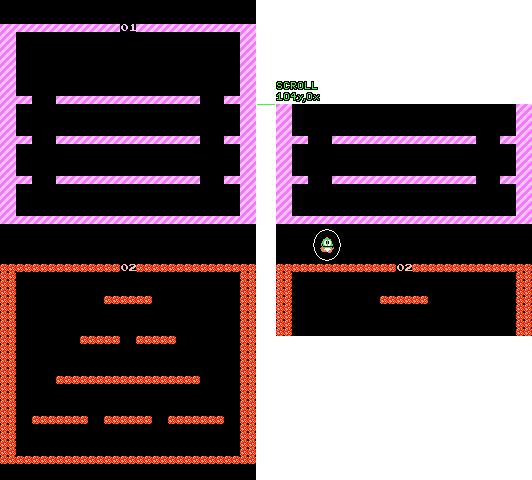
To begin with, there are actually two name tables [6]. Each of them has its own attributes for setting the color, but they have the same CHR. Cartridge equipment determines their position: either next to each other, or one above the other. The following are examples of two different types of locations - Lode Runner (1984) and Bubble Bobble (1988).

Scrolling
To take advantage of the presence of two name tables, PPU supports the ability to scroll by pixel at a time along the X and Y axes. It is controlled by a register with memory display at $ 2005: writing only two bytes at this address moves the entire screen to the desired number of pixels [7] . At the time of the release of NES, this was the main advantage over other home consoles, in which for scrolling often had to rewrite the entire video memory. Such an easy-to-use scheme led to the emergence of a large number of platformers and shooters, and became the main reason for such a great success of the system.
For a simple game, the field of which is only two screens wide, for example, Load Runner, it was enough to just fill in both name tables and change the scrolling accordingly. But in most scrolling games, the levels had an arbitrary width. To implement them, the game must update the off-screen portion of the name tables before they appear on the screen. The scrolling value is looped, but since the name table is constantly updated, this creates the illusion of infinite size.
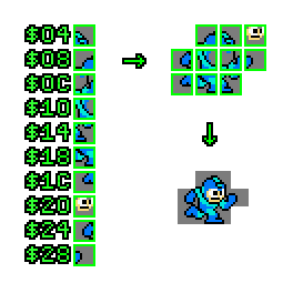
Sprites
In addition to scrolling through name tables, NES also had a completely different aspect of graphics: sprites. Unlike name tables that need to be aligned in grids, sprites could be positioned arbitrarily, so they could be used to display player characters, obstacles, projectiles and any objects with complex movement. For example, in the scene above from Mega Man (1987) to display a player’s character. points and energy strips are used sprites, which allows them to break out of the grid of name tables when scrolling the screen.
Sprites have their own CHR page [8] and a set of 4 palettes. In addition, they occupy a 256-byte page of memory. which lists the position and appearance of each sprite (as it turns out, the NES video memory is two and a half times larger than mentioned in the first part of the article). The format of these entries is rather unusual - they contain first a position in Y, then a tile number, then an attribute, then a position in X [9]. Since each record takes 4 bytes, there is a strict restriction: on the screen there can be no more than 256/4 = 64 sprites at a time.
Bytes Y and X specify the upper left pixel of the drawn sprite. Therefore, on the right side of the screen, the sprite can be cropped, but on the left side it leaves empty space. The byte of the tile is similar to the value in the name table, only for these tiles the sprites use their own CHR. An attribute byte is a packet of bits that performs three tasks: two bits are allocated to the palette, two bits are used to mirror the sprite horizontally or vertically, and one bit determines whether to render the sprite under the name tables [10].
Limitations
Modern systems allow working with sprites of any arbitrary size, but on NES the sprite due to CHR limitations had to have a size of 8 × 8 [11]. Larger objects are made up of several sprites, and the program should make sure that all the individual parts are rendered next to each other. For example, the size of a Megaman character can reach 10 sprites, which also allows you to use more colors, in particular for his white eyes and skin tone.
The main limitation associated with the use of sprites is that there should be no more than 8 sprites per raster line. If more than 8 sprites appear in any horizontal line of the screen, then those that appeared later will simply not be rendered. This is the reason for flickering in games with a lot of sprites; the program swaps the addresses of sprites in memory so that each of them is rendered at least sometimes.
And finally, scrolling does not affect sprites: the position of the sprite on the screen is determined by its Y and X values, regardless of the position of the scrolling. Sometimes this is a plus, for example, when the level moves relative to the player or the interface remains in a fixed position. However, in other cases, this is a minus - you need to move the moving object, and then change its position by the amount of change in scrolling.
Notes
[6] Theoretically, there are actually four name tables, but they are mirrored in such a way that only 2 of them contain unique graphics. When placed side by side, this is called vertical mirroring, and when name tables are located one above the other, horizontal mirroring.
[7] There is also a register that selects which name table to start rendering with, that is, scrolling is actually a 10-bit value, or 9-bit, if you consider mirroring.
[8] This is not always the case. PPU can be configured to use the same CHR page for name tables as for sprites.
[9] Perhaps this order was used because it corresponds to the data that the PPU must process for efficient rendering.
[10] This bit is used for various effects, for example, to move Mario under the white blocks in Super Mario Bros 3, or to render fog over sprites in Castlevania 3.
[11] PPU also has an option to enable 8 × 16 sprites, which is used in games like Contra, where there are tall characters. However, all other restrictions apply.
Part 3
In the previous parts, we talked about CHR data, backgrounds based on name tables, sprites and scrolling. And that’s practically all that a simple NES cartridge can do without additional hardware. But to go further, we need to explain in detail how the rendering works.
Rendering

Raster rendering with a pause for vblank
Like other old computers, NES was designed to work with CRT televisions. They draw scan lines on the screen, one at a time, from left to right, from top to bottom, using an electron gun, which physically moves to the point on the screen where these lines are drawn. After reaching the lower corner, a period of time called “vertical blank” (or vblank) sets in: the electron gun returns to the upper left corner to prepare for drawing the next frame. Inside NES, the PPU (Picture Processing Unit) performs raster rendering automatically, in each frame, and the code working in the CPU does all the tasks that the game should perform. Vblank gives the program the ability to replace the data in the PPU memory, because otherwise this data will be used for rendering. Most often, changes to the table of names and PPU palettes are made during this small window.
However, some changes in the state of the PPU can be made during screen rendering. They are called "raster effects." The most common action performed during screen rendering is to assign a scroll position. Thanks to this, part of the image remains static (for example, the game interface), and everything else continues to scroll. To achieve this effect, it is necessary to precisely select the time for changing the scrolling value so that it occurs on the desired raster line. There are many techniques for implementing this kind of synchronization between game code and PPU.
Split screen
The level scrolls, and the interface at the top of the screen remains stationary
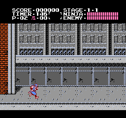
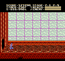
Firstly, the PPU has built-in hardware that processes the sprite in the zero memory position in a special way. When rendering this sprite, if one of its pixels overlaps the visible part of the background, a bit is set called “sprite0 flag”. The game code can first place this sprite where the screen split should occur, and then wait in a loop, checking the value of the sprite0 flag. Therefore, when the loop is exited, the game will know for sure which raster line is currently being rendered. This technique is used to implement simple screen sharing in many NES games, including Ninja Gaiden (1989), shown above [12]
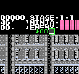
Sprite0 is located at Y $ 26, X $ a0. When its bottom row of pixels is rendered, the sprite0 flag is set
In some games, sprite0 flag is combined with another technique - predictably timed loop ("a cycle with predictable timing"): the program waits until several additional lines are rendered to divide the screen into more parts. For example, this technique is used in many Ninja Gaiden screensavers to create dramatic effects, such as a wind-driven field or an image of a castle in the distance. The game performs tasks such as playing music and waiting for the player to enter, at the beginning of the rendering of the frame, then uses sprite0 to search for the first division, and for all others it uses timed loops.
However, most games cannot afford to spend time waiting in cycles, especially in active scenes where CPU time is worth its weight in gold. In such cases, special equipment installed in the cartridges is used (called a mapper, because it uses its own mapping in memory (memory mapping)), which can receive a notification about the moment of rendering a certain raster line [13], which completely eliminates the need for waiting cycles. The game code can perform any of its tasks and at any desired time, so the processor is used more optimally. Most of the more modern games for NES, which have a lot of splits, use mappers in this way.
Here is an example from Ninja Gaiden 2, which uses a mapper to perform several partitions and simulate parallax scrolling, which creates a feeling of great speed, despite the static nature of the level. Note that all individual moving parts occupy strictly horizontal stripes; that is, none of the background layers can overlap with another. This is because separations are actually implemented by changing the scrolling of individual raster lines.
Bank switching
Mappers can perform many other functions, but the most common of them is switching banks. This is an operation in which the entire block of address spaces is reassigned to point to another part of the memory [14]. Switching banks can be performed with the program code (which allows you to create many levels and music in games), as well as with CHR data, thanks to which you can instantly replace the tiles referenced by name tables or sprites. If you use switching banks between frames, you can animate the entire background at a time. But when used as a raster effect, this allows you to draw completely different graphics in different parts of the screen. In games of the Ninja Gaiden series, this approach is used during the game process to render the interface separately from the level, as well as during splash screens, which allows you to store text and visual scenes in different CHR banks.
Animated background created by switching banks
Repeating in the background, each part of the name table corresponds to the same tile pattern
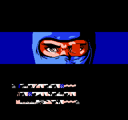
The upper half of the screensaver uses one bank of CHR. Sprites are used to render the eyes, which provides more colors.
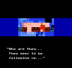
At the bottom, another CHR bank is used. When switching banks, the scrolling value is also reset
Bank switching can also be used for parallax scrolling, in a limited (but still impressive) way. If the scene has a part of the background made up of a short repeating pattern, then this same pattern can be contained in several banks with an offset by a different amount. Then this pattern can be scrolled to a certain value by switching to the bank with the corresponding offset. Such a technique can be used for parallax scrolling even with a background overlapping due to the presence of tiles that are not affected by memory switching [15]. The disadvantage of this method is that in total, all banks need to take up a lot of CHR space.
Metal Storm (1991) uses bank switching for layer-by-side scrolling
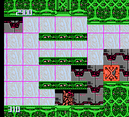
Repeating the name table allows you to create this effect.
Bank switching CHR is a very powerful tool, but it has its limitations. Although it is useful for animating the entire screen, this technique is not very suitable for replacing only a small part of the screen; this also requires name table changes. In addition, the amount of CHR in the cartridge is limited, and in order to switch to data, they must first exist. Finally, with the exception of scrolling based raster effects, the game always has a strict grid of name tables, which limits the dynamic range of graphic effects.
Other examples
The game Vice: Project Doom (1991) creates this flame effect by repeatedly setting the scroll position in each raster line. The character in the foreground is created from sprites that are not affected by scrolling.
Sword Master (1990) uses bank switching to scroll mountains in the distance, as well as split the screen for the interface and grass in the foreground.
Acknowledgments
I would not be able to generate all this graphics for an article without the powerful debugging functions provided by the FCEUX emulator. In addition, the NesDev site wiki has become a useful source of information about sprite0:
Notes
[12] In fact, the situation with Ninja Gaiden is a bit more complicated. The game uses 8 × 16 sprites sprites - a special mode provided by PPU that renders sprites as vertically superimposed pairs. That is, sprite0 is completely transparent, and sprite1 has a row of pixels at the very bottom. He also sets the z-layer of these sprites so that they are rendered behind the blackness of the interface, which makes everything invisible.
[13] This is pretty tricky to implement. The game code writes the desired raster line to the address space of the mapper. The mapper then intercepts the PPU memory access requests, counting when a new raster line is rendered. Upon reaching the desired raster line, it generates a program interrupt (IRQ) during which the game code is executed, doing what is needed during this particular raster line.
[14] Switching is performed by mapping equipment to memory, intercepting memory access operations, and redefining the physical location from which data is obtained. The result is instantaneous, but has a large fractionality, which is why the address ranges vary by 4 KB or 8 KB.
[15] The only way to switch CHR banks without affecting each tile is to either duplicate the tile data between the banks, or have a mapper with less grain. With this mapper, you can switch a smaller part of the bank, for example, only 1 KB at a time, and everything else will remain unchanged.
All Articles