What a voltmeter shows, or math sockets

What is this article about
Today I will briefly step back from my usual topic of visual programming of controllers and turn to the topic of voltage measurements right in it, in the socket!
This article was born from discussions over tea, when a debate broke out among “all-knowing and omniscient” programmers about what many of them do not understand, namely: how the voltage is measured in the outlet, which shows an AC voltmeter, what distinguishes the peak and actual voltage values .
Most likely, this article will be interesting to those who begin to create their devices. But perhaps it will help someone experienced refresh their memory.
The article talks about what voltages are in the AC network, how they are measured and what should be remembered when designing electronic circuits.
A brief and simplified mathematical justification has been given to everyone so that it is clear not only how, but also why.
Whoever is not interested in reading about integrals, GOSTs and phases - can immediately proceed to the conclusion.
Introduction
When people start talking about the voltage in the outlet, very often the stereotype “in the 220V outlet” hides the real state of affairs from their eyes.
To begin with, according to GOST 29322-2014 , the mains voltage should be 230V ± 10% at a frequency of 50 ± 0.2Hz (phase-to-phase voltage 400V , phase-neutral voltage 230V ). But in the same GOST there is a note: " However, 220/380 V and 240/415 V systems still continue to be used ."
Agree that this is not at all the same unequivocal “ in the 220V socket ” that we are used to. And when it comes to “ phase ”, “ linear ”, “ acting ” and “ peak ” voltages - in general the porridge turns out to be notable. So how many volts are in the outlet?
To answer this question, we will start with how AC voltage is measured.
How to measure alternating voltage?
Before delving into the jungle of alternating current and voltage circuits, we recall the school physics of direct current circuits.
DC circuits are a simple thing. If we take some active load (let it be an ordinary incandescent lamp, as in the figure) and plug it into a direct current circuit, then everything that happens in our circuit will be characterized by only two quantities: the voltage at the load U and the current flowing through the load I. The power that is consumed by the load is uniquely calculated according to a formula known from school: .
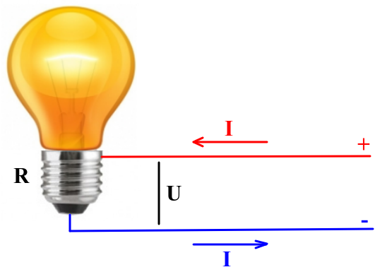
Or, given that Ohm’s law , then the power P consumed by the light bulb can be calculated by the formula .
With alternating voltage, everything is much more complicated: at every moment of time - it can have different instantaneous values. Therefore, at different times, on the load connected to an AC voltage source (for example, on an incandescent lamp plugged into an outlet), different power will be released. This is very inconvenient in terms of describing the electrical circuit.
But we were lucky: the voltage form in the socket is sinusoidal. A sine wave, as you know, is completely described by three parameters: amplitude, period and phase. In single-phase networks (and an ordinary socket with two holes is exactly a single-phase network) you can forget about the phase. The figure shows in detail two periods of a single-phase mains voltage. The same in the outlet.
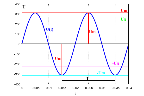
Consider what all these letters in the picture mean.
Period T is the time between two adjacent minima or adjacent maxima of the sine wave. For the RF lighting network, this period is 20 milliseconds , which corresponds to a frequency of 50 Hz . The frequency of voltage fluctuations of the electric network is maintained very accurately, to a fraction of a percent.
Obviously, at any two points of the sinusoid, separated from each other by an integer number of periods, the voltages are always equal to each other.
The amplitude Um is the maximum voltage, the peak of the sinusoid. We will talk about the current voltage Ud a little lower.
The voltage in the outlet (or single-phase network) is described by the formula
where t is the current time, Um is the amplitude (or peak value) of the voltage, T is the period of the mains voltage.
If with a single-phase alternating voltage everything is more or less clear, then we will try to calculate the power that is released on our favorite incandescent lamp when it is plugged directly into a power outlet.
Since an incandescent lamp is an active load (and this means that its resistance does not depend on the frequency of voltage and current), the instantaneous power allocated to an incandescent lamp plugged into a socket will be calculated by the formula
where t is the current time, and R is the resistance of the incandescent lamp with a heated spiral. Knowing the amplitude of the alternating voltage Um , we can write:
It is clear that instant power is an inconvenient parameter, and in practice it is not particularly necessary. Therefore, the power averaged over a period is usually used.
It is the average power indicated on bulbs, heaters and other household irons.
The average power is calculated in the general case by the formula:
And for our sinusoid - by a much simpler formula:
You can substitute the function and take the integral, if you do not believe it.
Do not think that about power I just remembered out of harm. Now you will understand why we needed her. We pass to the next question.
What does the voltmeter show?
For DC circuits, everything is clear here - the voltmeter shows the only voltage between the two contacts.
With AC circuits, things are more complicated again. Some (and some of them are not so few as I was convinced) believe that the voltmeter shows the peak value of the voltage Um , but this is not so !
In fact, voltmeters usually show the effective or effective , it is also the rms voltage in the network Ud .
Of course, we are talking about AC voltmeters! Therefore, if you measure the network voltage with a voltmeter, be sure to check that it is in the AC voltage measurement mode .
I will make a reservation that “peak voltmeters” showing the amplitude values of the voltage also exist, but in practice, when measuring the voltage of the mains in everyday life, they are usually not used.
We will understand why such difficulties. Why not just measure the amplitude? Why did you come up with some kind of “effective value” of voltage?
And it's all about power consumption. I didn’t just write about her. The fact is that the effective (effective) value of the alternating voltage is equal to the magnitude of such a constant voltage, which, in a time equal to one period of this alternating voltage, will do the same work as the alternating voltage under consideration .
Or, in a simple way, the incandescent light will shine equally brightly, whether we plug it into a 220V DC network or into an AC circuit with an effective voltage value of 220V .
For those who are already familiar with the integrals or have not forgotten mathematics, I will give a general formula for calculating the effective voltage of an arbitrary shape:
From this formula, it also becomes clear why the effective (effective) value of the alternating voltage is also called “rms”.
Note that the radical expression is the same “power averaged over a period”, you only need to divide this expression by the load resistance R.
In relation to the sinusoidal form of voltage, the terrible integral after simple transformations will turn into a simple formula:
where Ud is the effective or rms voltage value (the same as the voltmeter usually shows), and Um is the amplitude value.
The effective voltage is good because for an active load, the calculation of the average power completely coincides with the calculation of DC power:
This is not surprising if we recall the definition of the effective voltage value, which was given a little higher.
Well, finally, let's calculate what the amplitude of the voltage in the outlet is " 220V ":
In the worst case, if you have a 240V network, and even with a tolerance of + 10%, the amplitude will be as much !
Therefore, if you want your devices powered by the network to work stably and not burn out, select elements that withstand peak voltages of at least 400V . Of course, we are talking about elements that are directly supplied with mains voltage.
I note that for a non-sinusoidal waveform, the effective voltage value is calculated using other formulas. Who cares - they can take the integrals themselves or turn to directories. We are interested in the supply network, and there should always be a sine wave.
Phases, phases, phases ...
In addition to the usual single-phase lighting network ~ 220V, everyone has heard about the three-phase network ~ 380V . What is 380V ? And this is the interphase effective voltage .
Remember, I said that in a single-phase network you can forget about the phase of a sinusoid? So, in a three-phase network this cannot be done!
In simple terms, the phase is a time shift of one sinusoid relative to another. In a single-phase network, we could always take any moment in time as a reference point - this did not affect the calculations. In a three-phase network, it is necessary to consider how far one sine wave is from the other. In three-phase AC networks, each phase is separated from the other by a third of the period or 120 degrees. Let me remind you that the period is also measured in degrees and the full period is 360 degrees.
If we take an oscilloscope with three beams and are attached to three phases and one zero, we will see such a picture.
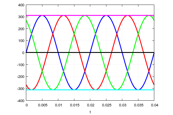
" Blue " phase - starts from zero. The “ red " phase is a third of the period ( 120 degrees) later. And finally, the “ green ” phase begins two-thirds of the period ( 240 degrees) later than the “ blue ” phase. All phases are absolutely symmetrical with respect to each other.
Which phase to take as a reference point is not important. The picture will be the same.
Mathematically, we can write the equations of all three phases:
Blue phase:
" Red " phase:
Green phase:
If we measure the voltage between any of the phases and zero in a three-phase network, then we get the usual 220V (or 230V or 240V - as luck would have it, see GOST ).
And if you measure the voltage between the two phases - then we get 380V (or 400V or 415V - do not forget about it).
That is, a three-phase network is multifaceted. It can be used as three single-phase networks with a voltage of 220V or as one three-phase network with a voltage of 380V .
Where did 380V come from? But from where.
If we substitute our data on any two phases in the formula for calculating the effective voltage, we will get:
or, simplifying:
Udf is the acting interphase , it is also a linear voltage.
Given that the amplitude of each phase we get that for interphase voltage. The figure clearly shows how an interfacial voltage is formed, which is designated F1-F2 from two phase voltages of phases F1 and F2 . The voltage of phases F1 and F2 is measured relative to the neutral wire. The line voltage F1-F2 is measured between two different phase conductors.
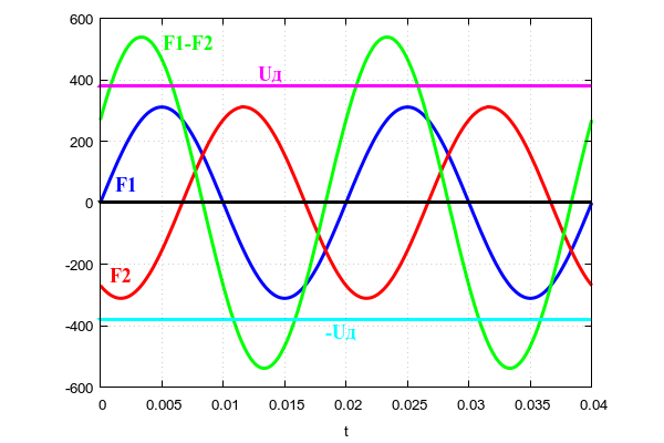
As you can see, the current interphase voltage is greater than the amplitude of the sinusoidal voltage of one phase.
The amplitude of the interfacial voltage is:
For the worst case (network 240V and phase-to-phase voltage 415V , and even 10% above) the amplitude of the phase-to-phase voltage will be:
Keep this in mind when working in three-phase networks and choose elements rated at no less than 650V if they have to work between two phases!
I hope now it’s clear what the AC voltmeter shows?
Conclusion
So, very briefly, almost on the fingers, we got acquainted with what voltages act in household AC networks. To summarize the summary of all of the above.
- Phase voltage is the voltage between the phase and the neutral conductor.
- Linear or interphase voltage is the voltage between two different phase wires of the same three-phase network.
- In RF alternating current networks, there are three, although close, but different standards (phase / linear): 220V / 380V, 230V / 400V and 240V / 415V alternating current with a frequency of 50Hz.
- An alternating current voltmeter usually shows the effective (it is the rms , it is also effective ) voltage, which times less than the peak (amplitude) voltage in the network.
- In the worst case from the point of view of standards, the peak phase voltage is approximately 373V, and the peak line voltage is 645V. This should be considered when developing electronic circuits.
I hope this article helped someone sort out the topic and answer some questions for themselves.
You can send suggestions and wishes, noticed typos and just opinions in a comment or by mail: shiotiny@yandex.ru .
All Articles