In the first part I talked about the concept of the project. In the second part, we disassemble the design of the MIRO robot by bones (many pictures).
At the very beginning I say Thank you all for the ideas and support after the first publication ! It takes a little time to build a joint project support format. Therefore, everyone who decided to join, I ask you to give me a little this time - soon everything will be!
Table of Contents: Part 1 , Part 2 , Part 3 , Part 4 .
As I mentioned in the first part, the old MIRO versions were practically devoid of plastic parts made using a 3D printer, and were almost entirely made of sheet materials by laser cutting. Acrylic and plywood were used. Plus, there is only one - the relative cheapness of small parties. Well, a relatively high speed of production of the products themselves. But in the process of operation, I had to move away from this approach. The main reasons are that the parts assembled from sheet materials, fasteners are inaccurate, unreliable, carry a lengthy assembly with a bunch of small gadgets, washers, locks. The whole structure lacks a pleasant feeling of being “knocked down." Yes, and a lot of restrictions on the shape and geometry. With 3D printing, everything is much simpler.
One of the main requirements in the design of the case, I identified the simplicity of printing - if possible, the details of the case should be printed without any support at all. Well, or with some very simple supports. So that everything was honest - I could print a great robot on our cheap ANET A6 straight out of the box, as they say.
All design is done in Autodesk Fusion 360.
The robot consists of many body parts, which can conditionally be divided into three groups:
- group of parts made by 3D printing technology
- group of parts that are made by laser cutting technology
- serial products.
The convention here is that what is meant is the most obvious way to produce parts. But no one bothers to print the details of the second group on the printer.
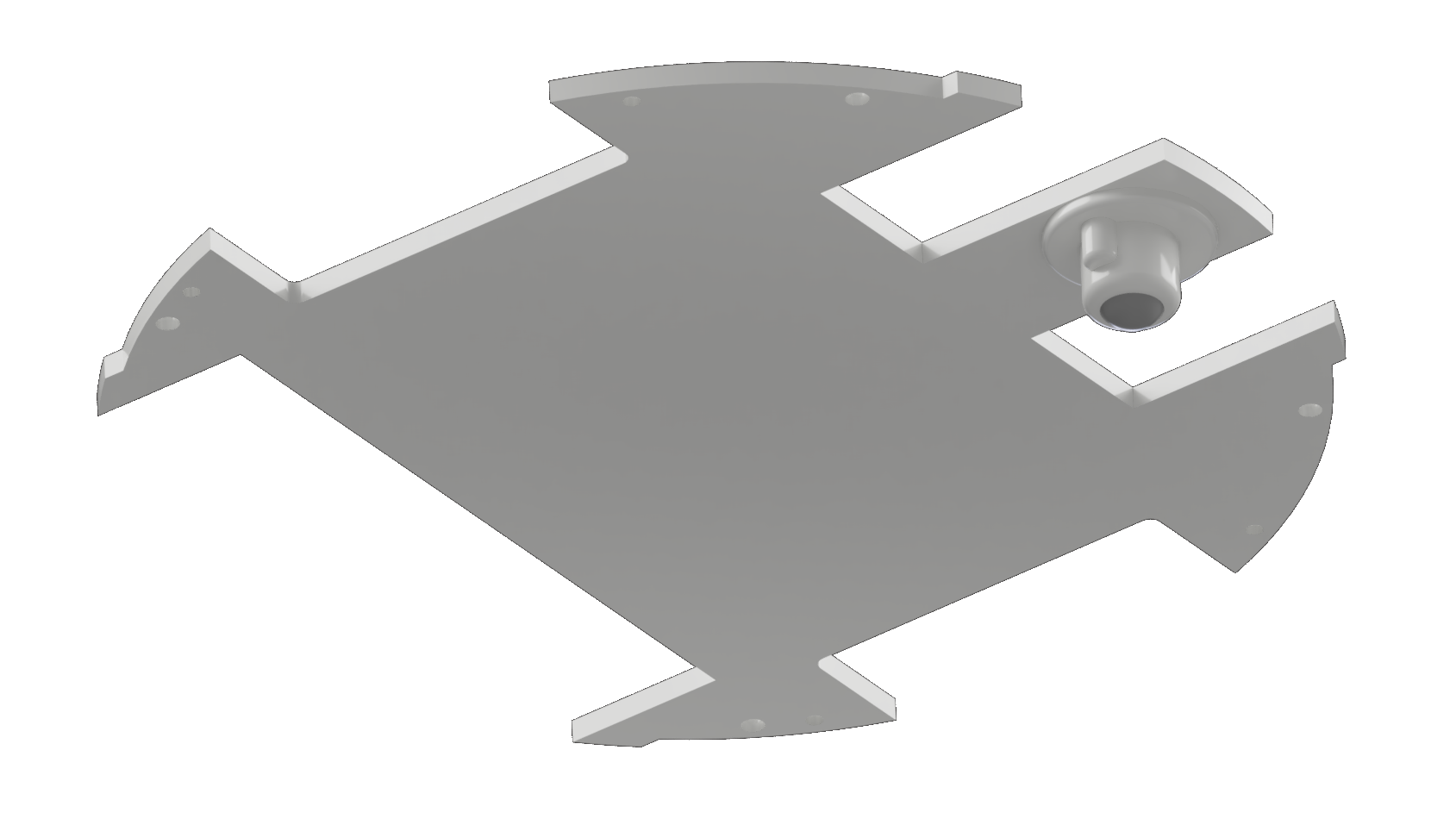
So, the robot gathers around a central platform made of 4mm plywood (group 2). Because in this part there are a lot of holes and slots, and it is the carrier itself, it is not recommended to use acrylic for its production - it is quite fragile.
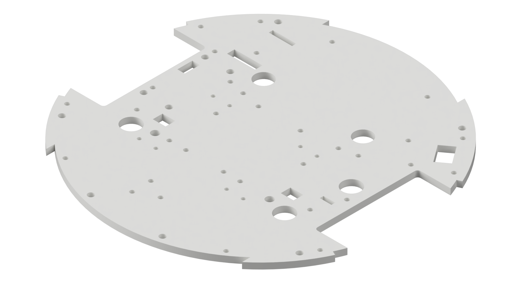
Almost all parts are interconnected by bolts of various lengths and M3 nuts. And only for mounting boards you have to use M2.5. The printed parts have cavities for “pressing” the nuts (tight bait).
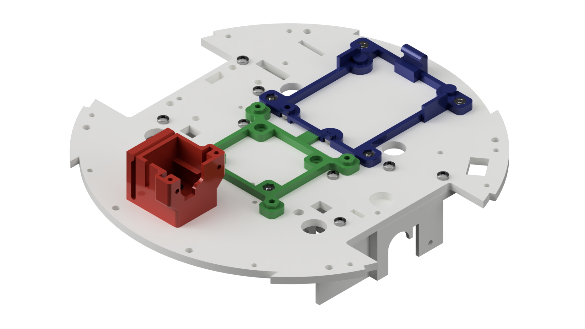
On top of the platform are attached two substrates (group 1) for printed circuit boards: ARDUINO and Raspberry Pi.
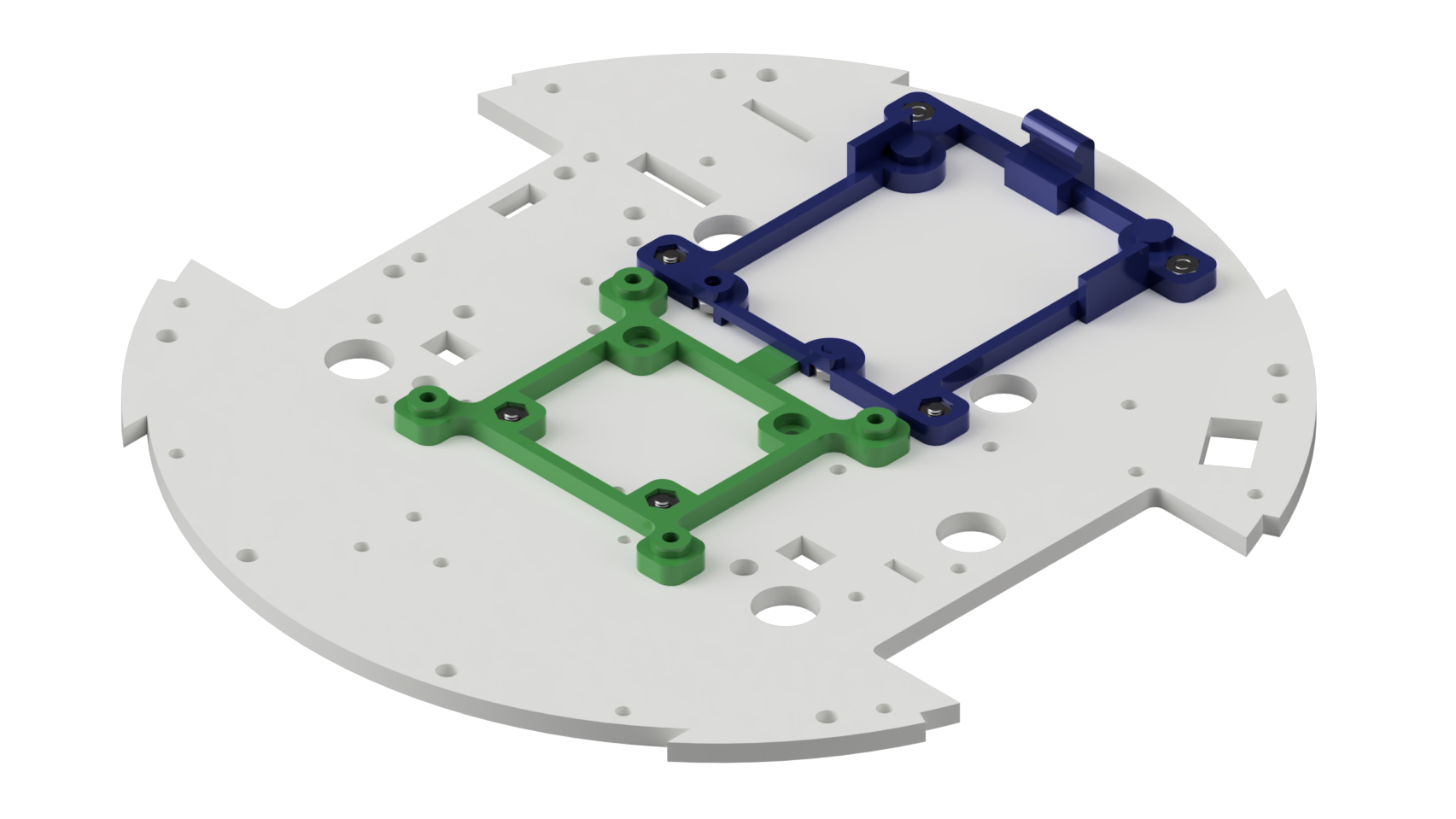
These substrates, together with additional cavities for nuts in the mountings of the gearmotors, allow you to remove from the robot and replace any controller, motor driver, voltage regulator - in a word, almost all robot electronics by removing only the top cover.
The substrate for the Raspberry Pi is fixed on two bolts on the one hand, and on the other hand has a tab inserted into the slot under the substrate for the ARDUINO board. From below, nuts M2.5 are pressed into the substrates for subsequent bolt fastening of the corresponding boards.
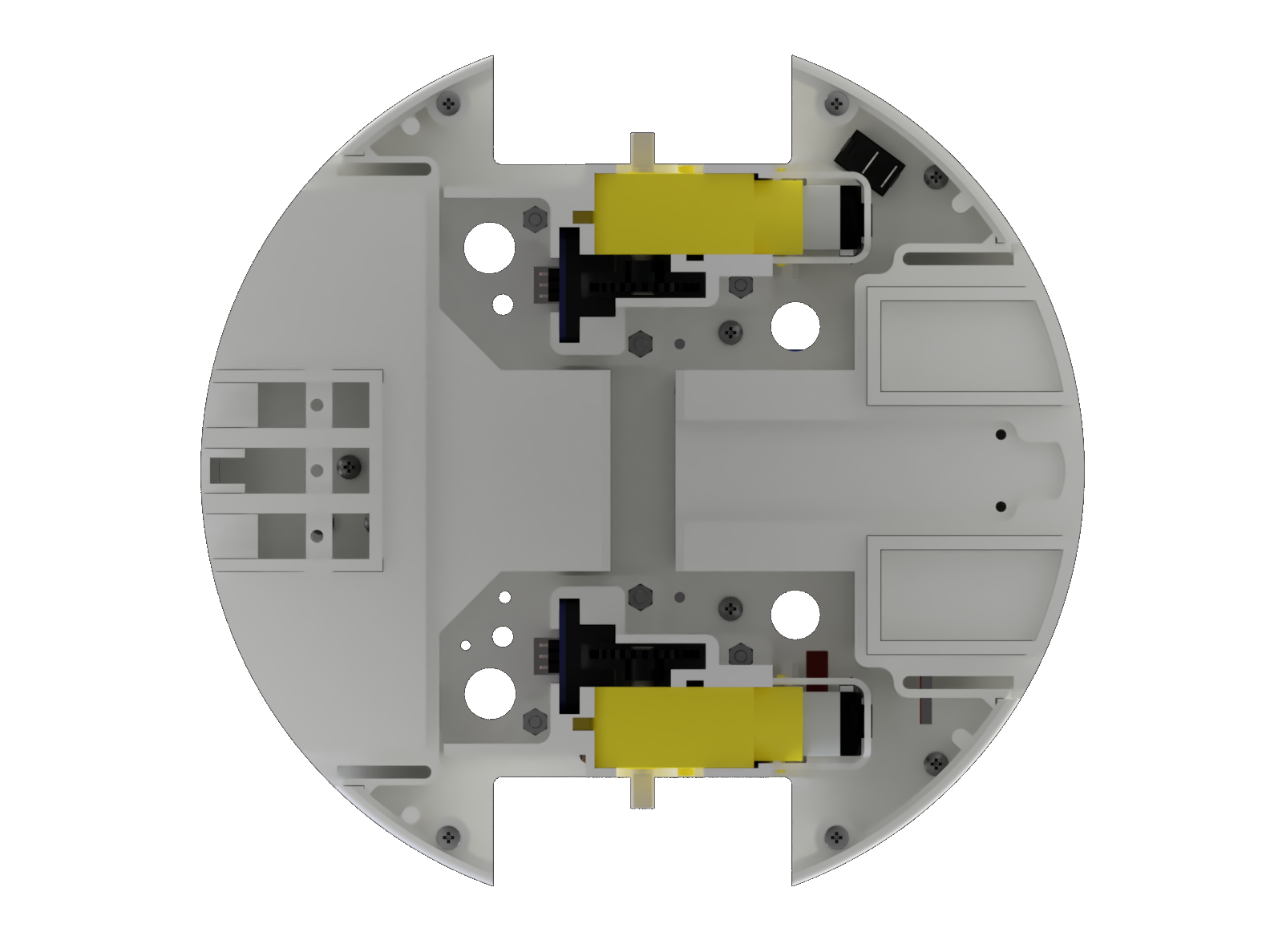
Bottom to the central platform are mounted mounts (group 1) for gear motors and optical slot encoders.
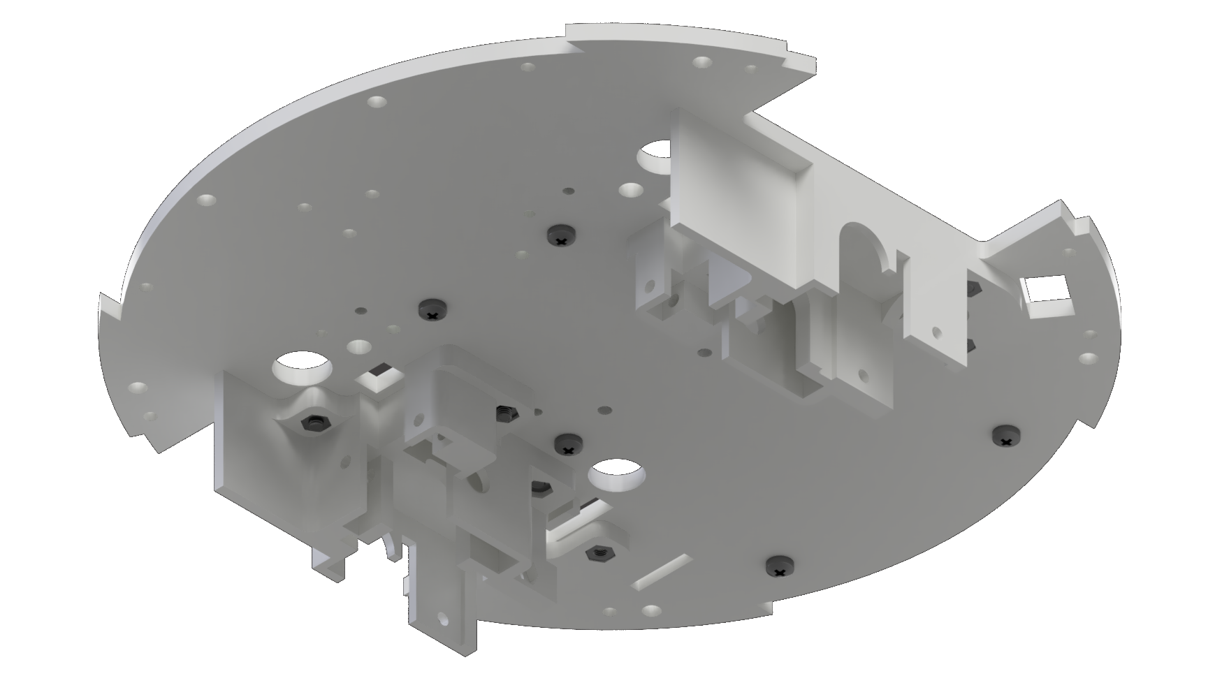
In front of the three bolts installed another detail of group 1 - the holder of the servo camera.
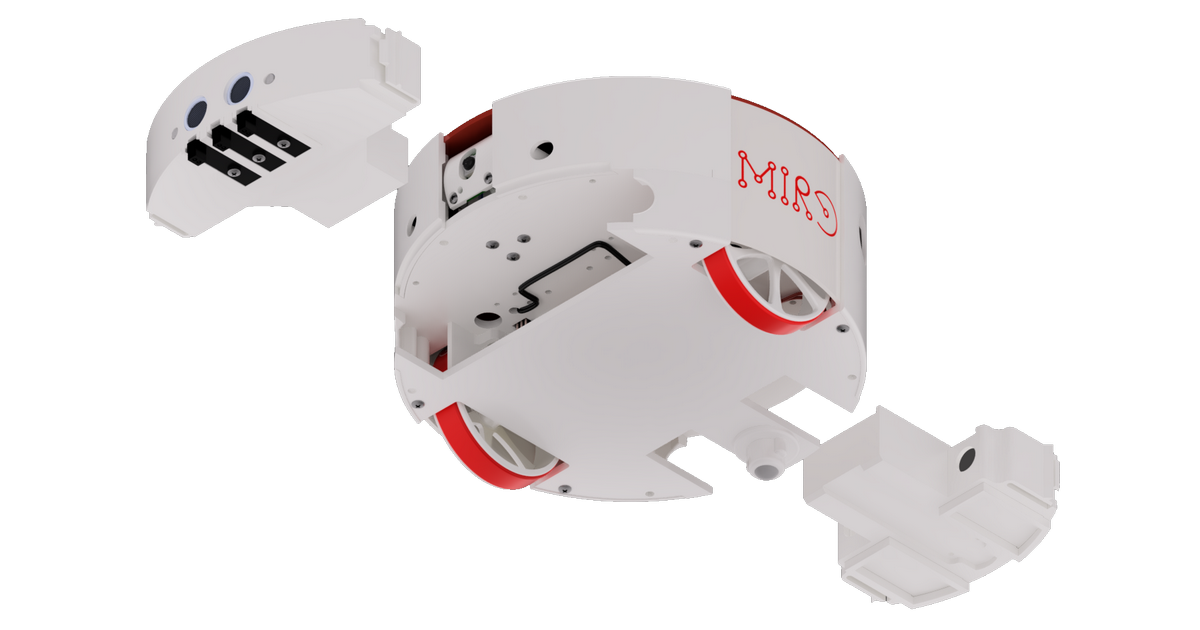
In principle, at this stage, you can begin to mount the electronics. The Raspberry Pi board is not shown on the render, because it dropped somewhere from the project, but it is there on a green substrate. The expansion card is also shown as “some kind” - as I indicated in the first article - the “sandwich” can be performed in different ways (either ARDUINO UNO and the expansion card with ESP8266 and three-pin pin connectors on top, or the ARDUINO + WiFi card and the expansion card are similar the one in the picture).
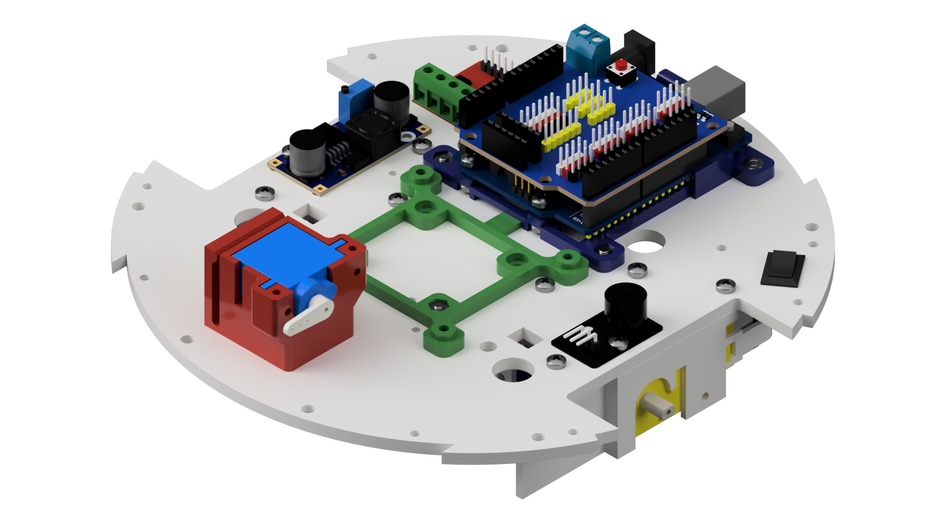
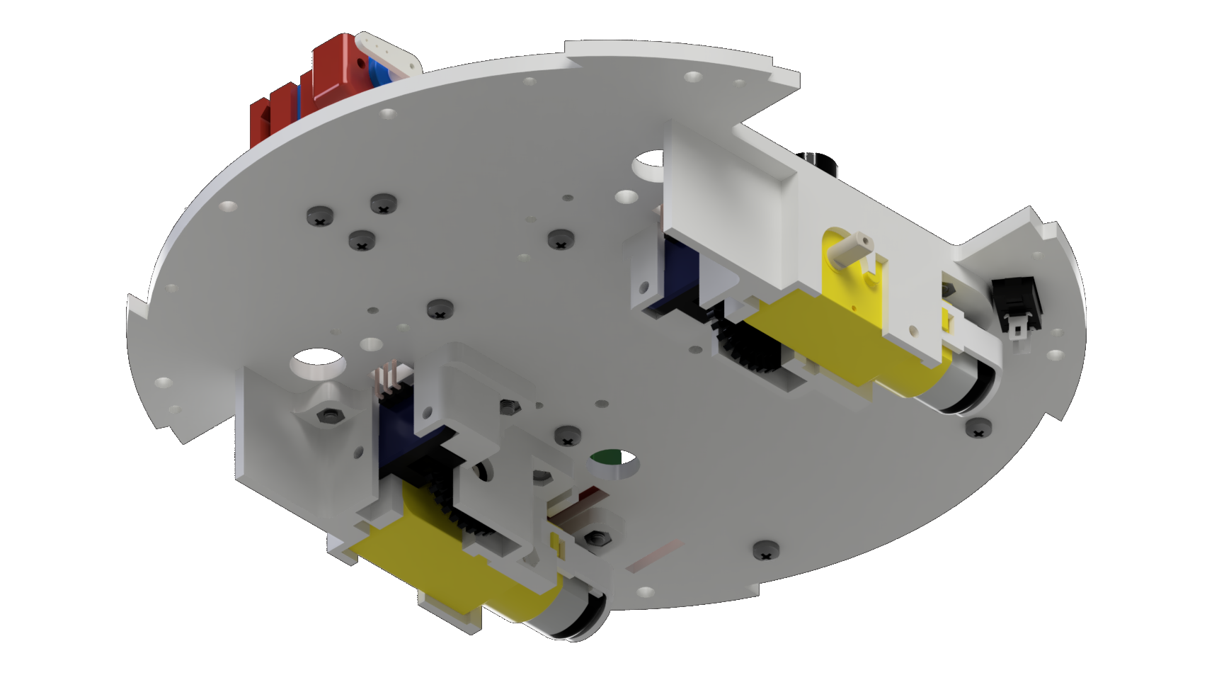
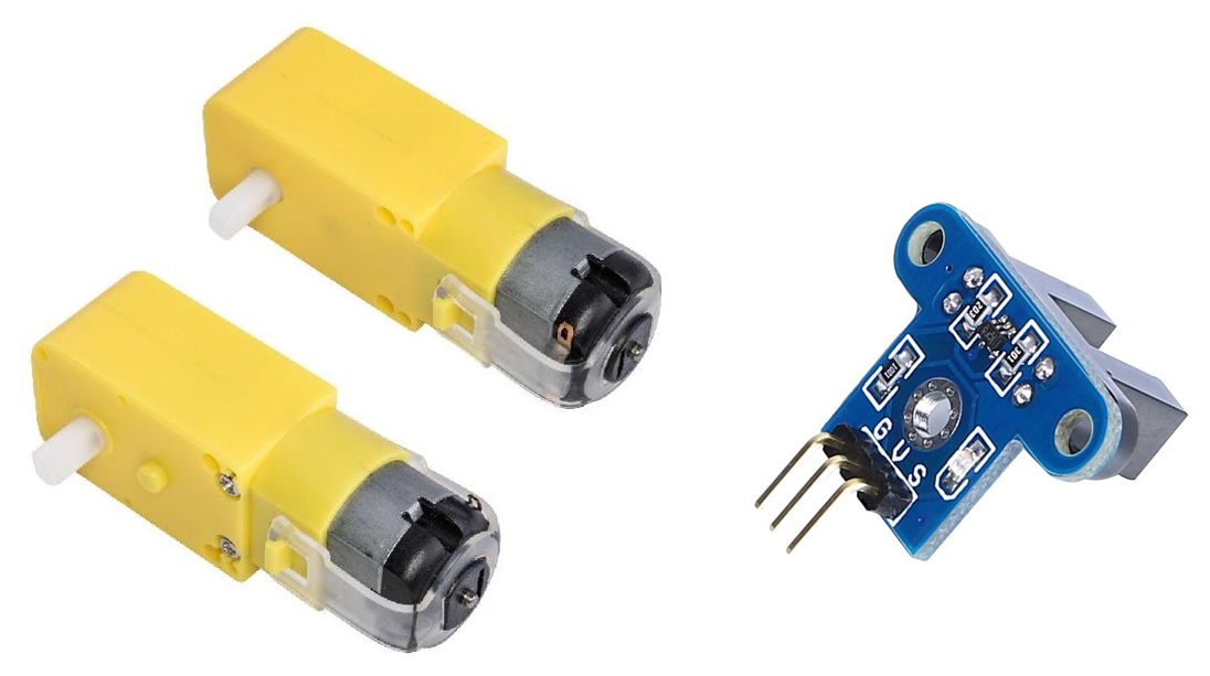
As you can see, MIRO uses the usual cheap “yellow” motors. This is one of the most disgusting compromises in the mechanics of the project. They are unreliable, they are noisy. But they are affordable. First of all, by availability in any corner. In addition, as is known, slotted encoders are easily delivered to them after the gearbox. And taking into account the fact that the signal from the encoders is interrupted by the simple and, again, affordable ATMEGA328, this is what you need. Some motors with an encoder to the gearbox "put" this chip immediately. In general, the decision to use these particular motors is a painful compromise. But at MIRO we did everything to slightly improve their operational properties - motor mounts tightly hug these motors from all sides, reducing the usual alignment of wheels for Chinese sets and additional backlash caused by insufficient rigidity of the gearbox. Encoders, as in the picture, are simply inserted into the grooves of the printed part of the motor mount.
Next, 8 printed parts of the walls of the outer casing (group 1) are attached to the platform: 4 from above and 4 from below.

From the bottom, everything is closed by a cover (group 2), into which the rear support wheel is installed through the adapter-spacer (group 1). Jockey wheel - serial, widespread, searched for “3PI N20 UNIVERSAL BALL WHEEL”.
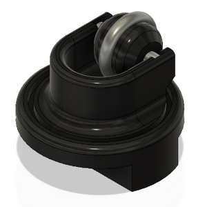
A rather big problem, as it turned out, was to find a normal support wheel for a small robot. All ball wheels have one minus - a hard ball through which all vibrations from movement are transmitted to the robot body. And the wheels with the hub are also all plastic. We even developed for MIRO our own wheel on the hub - with a tread made of a standard size O-ring. But his project has not yet been loaded normally. It is not easy to manufacture, because it uses two miniature bearings at once. They are easy to order from China, but they are definitely not available at hand. But the quality of the robot’s movement, the MIRO feel with this wheel is completely different - the robot moves softly and quietly. Who visited the site mirorobot.ru , he could notice the mention of him in the projects.
On the right and left, as well as behind the robot, instead of plastic printed parts, inserts made of thin (1 mm) PVC plastic (group 2) are used. To fix the inserts in the walls of the outer casing there are grooves. Through the side inserts, it is easy to get to the Raspberry Pi USB connectors, and through the rear insert, to the ARDUINO USB board (or ARDUINO + WiFi) without removing the upper case cover.

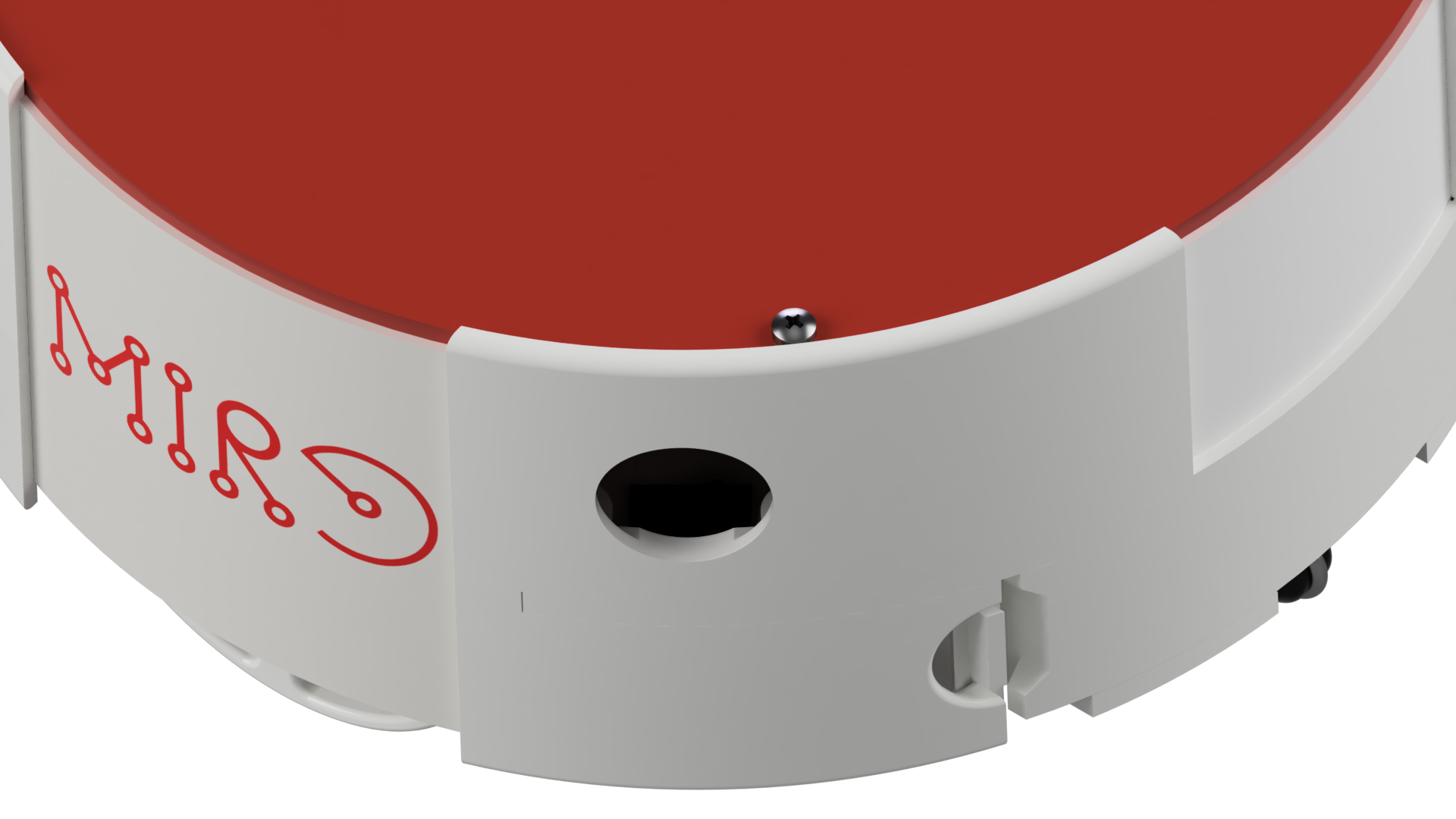
In the top cover (group 2) there is a hole for installing the mortise handle (group 1) for carrying the robot.
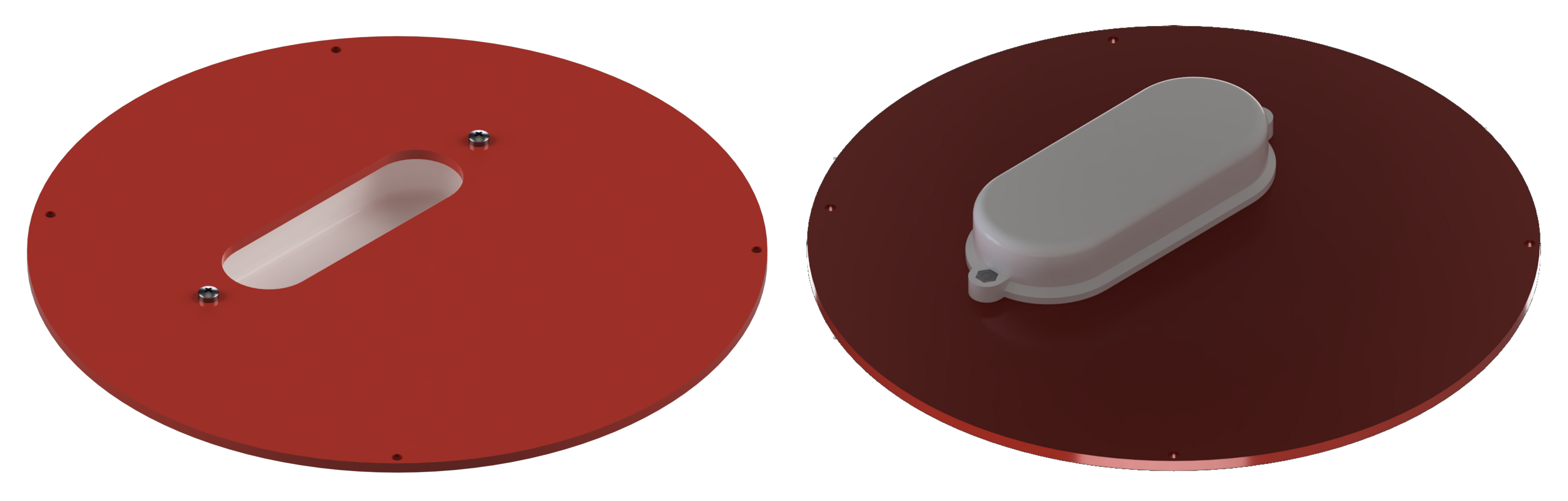
The top cover itself is mounted on the robot with the same bolted connection (see the main illustration for the first publication ).
The driving wheels of the robot are made using 3D printing technology, together with the tread, which is a serial product - a silicone bracelet (group 3) with a diameter of 65 mm. This is the most common size - if you get such a bracelet for some kind of hangout - 90% that it fits. Well, or you can buy it in advertising companies that manufacture and sell various branded products ("merch").
Front and rear modules (group 1) are mounted on the latches on the front and rear of the robot.
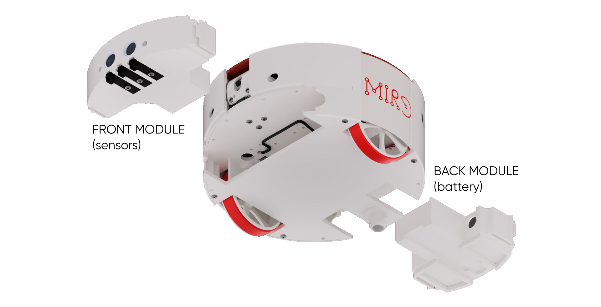
Here is an example front module SENS1.
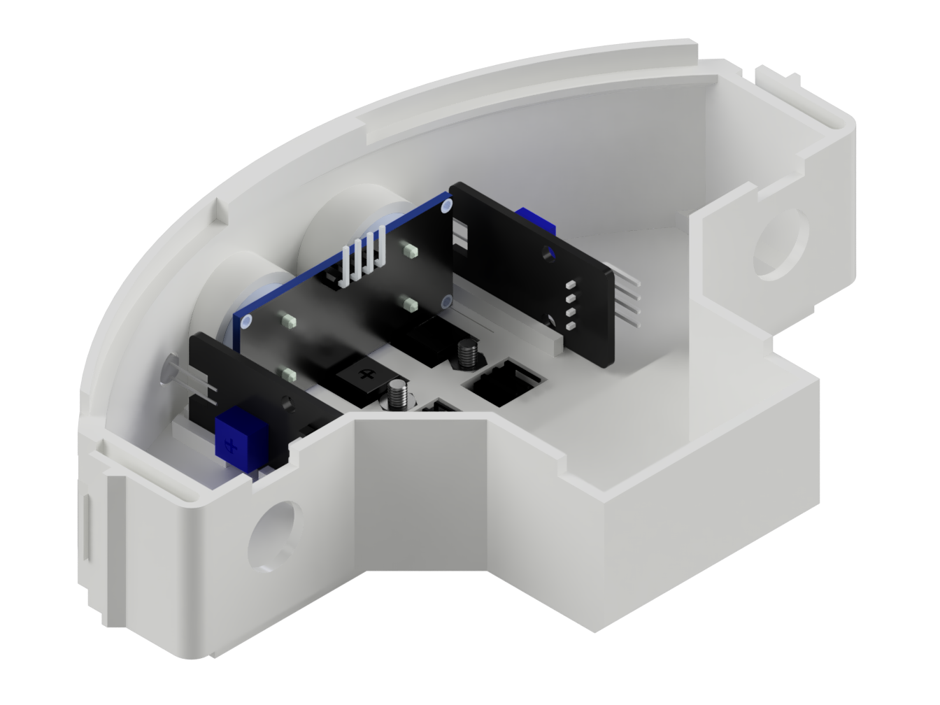
The modules on top do not close at all - they are simply inserted along the guides between the bottom cover and the central platform.
For their convenient removal, in the details of the walls of the case there are cutouts for the fingers, so that it is convenient to squeeze the latches and remove the module.
The figure clearly shows the position of the modules in the robot with the bottom cover removed.

The battery is located in the rear module (now it is a dual 18650, 7.4V), but a decision has already been made to slightly increase the depth of the rear module for LiPo battery 2200-2500mAh (checked - included).
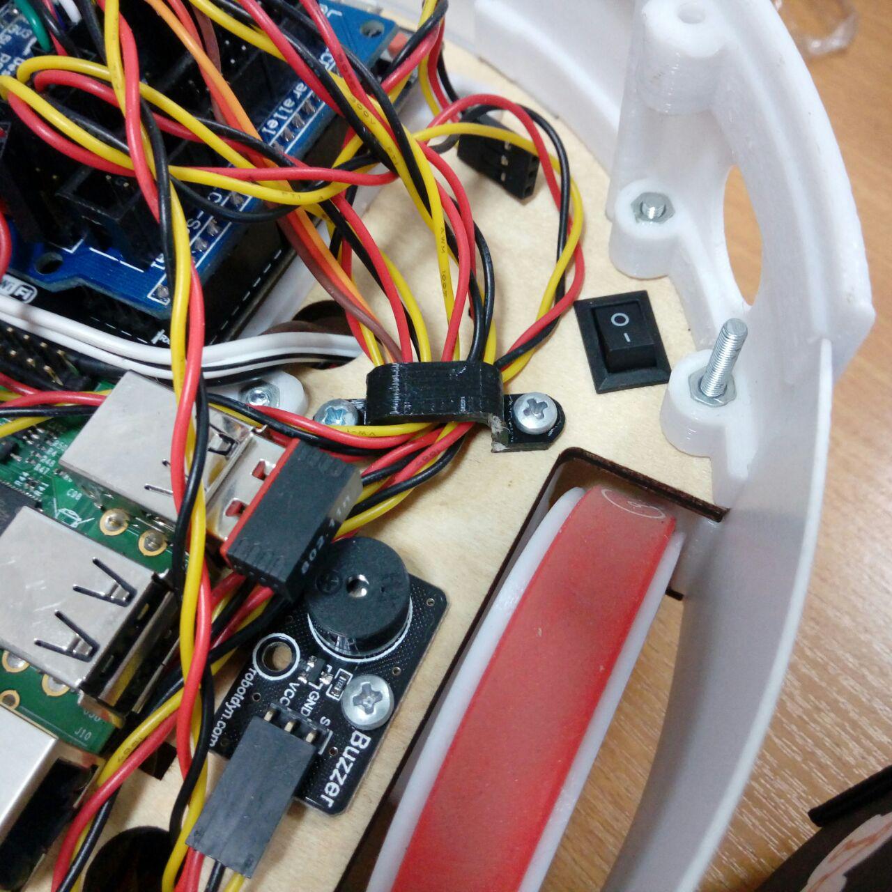
In the rear left wall of the case there is a hole for a finger (yes, yes, for the index finger) to access the power toggle switch. This decision was made consciously - I did not want to make a toggle switch on the lid or the outer wall of the case, which is easy to accidentally switch.
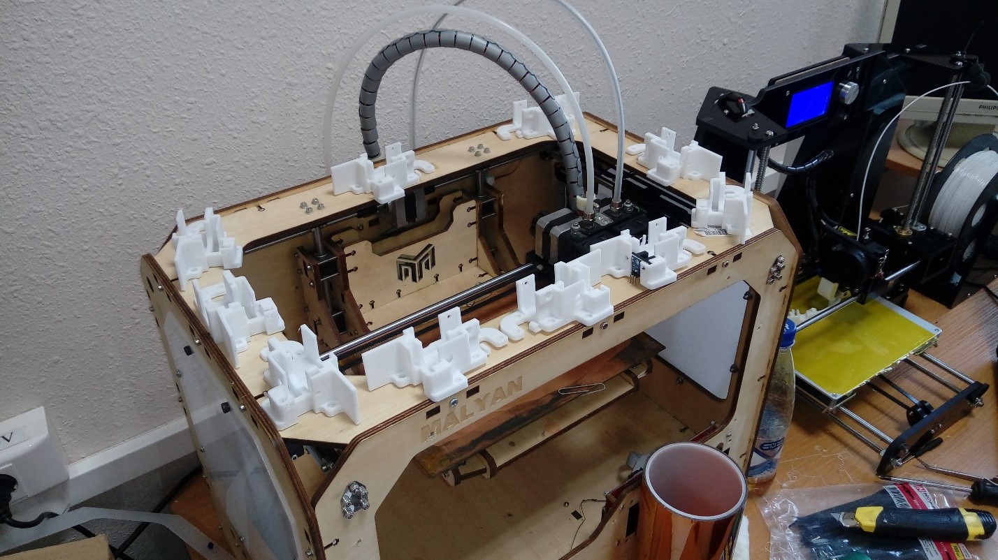
Now about the tasks (not about the problems, because all this is being solved). Firstly, it is not shown on the renderers, but in reality inside the robot there is chaos from the wires (photo attached).
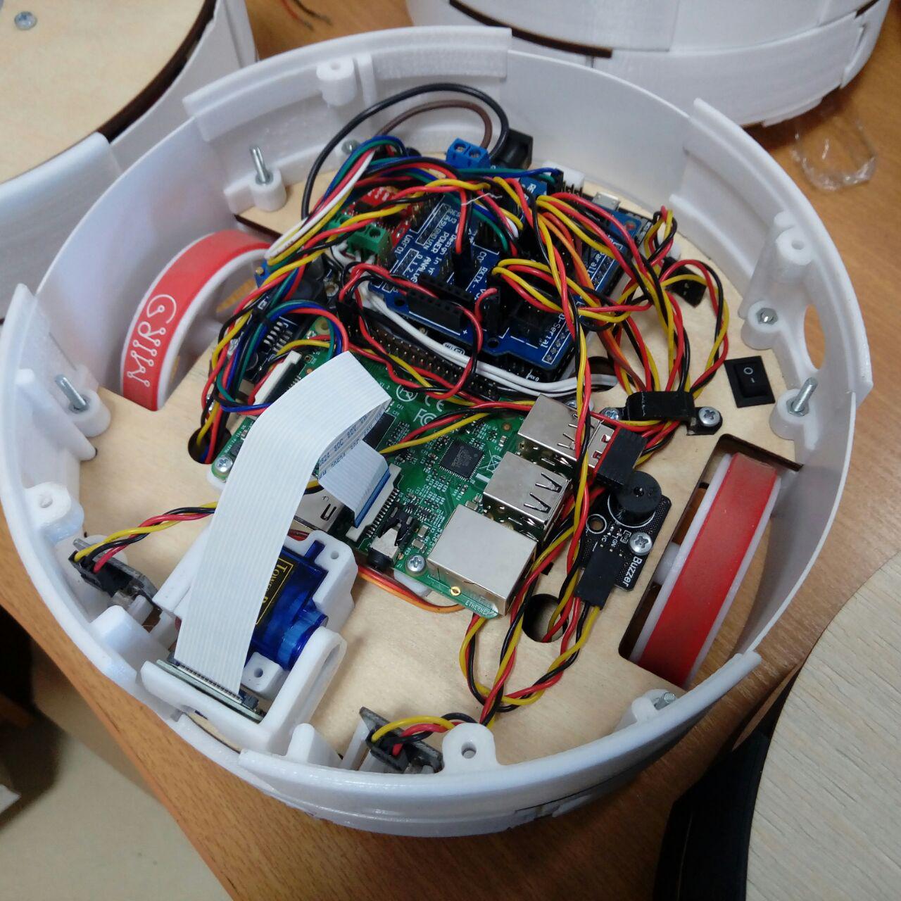
We partially tidied them up a bit with that black clip on the right, fixed in the same holes for fixing the left motor, but still chaos. We need to deal with this.
Secondly, and this is the task associated with the first, the modules are now connected rather poorly - wires are routed through the technological holes in the central platform and the module housings and are seated on the pin connectors from both ends (in the case of the rear module, the battery is connected to the mating connector on wire). This is certainly not beautiful.
And here it’s like you don’t rest, but the only solution suggests itself - you need your own motherboard. At least purely to forward the output of the switching connectors of the modules under the central platform (inside the “father” case, “mothers” stick out of the modules) - so that the modules are completely isolated units with a standard mechanical interface. We plan to do this. In principle, the board will definitely have no more than two layers, so everyone will be able to fulfill it at home. And we have a machine.
Six months ago, I was making a video illustrating the assembly process. Since then, the design has changed somewhat. Most importantly, we abandoned the lower central compartment for the battery - such an arrangement without efficient filling of the rear module led to insufficient robot stability during braking. Ergonomics have been slightly improved, details have been facilitated. But other fundamental changes were not made. Therefore, this video illustrates well the device of the robot. And new things are not a priority yet, especially since the animation engine in Fusion 360 is buggy.
I foresee the question of why not immediately print the case with all these parts of the external walls and the central platform as one integral part? This was a difficult decision - in order to enable the owners of printers to make the robot, with a table size of less than 205 mm in length and width. The diameter of the robot is just 201 mm. Of course, today most even inexpensive printers have a table under 300 mm, but users have a lot of printers with much smaller print area.
But the details for printing on large printers are already ready and will be published in the near future - we used them to make master models for casting in silicone.
The repository also contains a set of parts for printing in STL format with a layer thickness of 0.2 mm with prepared easily removable supports (folder STLwSUPPORTS). Turn off all support in the slicer and just print on the correct plane. Where there is a “right” plane will help to determine the document MIRO PARTS LIST & MANUFACTURING (from the same repository), in which all the details are depicted in isometric view from above / side as if they were lying on the printing table.
Well, I hope more or less outlined. I omitted some of the little things, like the individual parts of the guide modules and the camera holder. If there are strange places - write, I will adjust. Well, a constructive discussion is always happy.
In the next part, we will analyze the software on the ESP8266 side.