ROS truck trolley. Part 5. Working in rviz and gazebo: xacro, new sensors
Continuation of the series of articles.
Previous posts in the series:
1. Part 4
2. Part 3
3. Part 2
4. Part 1
Last time, the following goals were achieved:
In this post, we will arrange the project in the form of xacro modules so that it becomes more readable (earlier, for clarity, we pushed the entire description into one xacro file). Add a virtual video camera and imu. Let’s see how to add gazebo to foreign objects.
First, let's check whether the terminal works on roaming through the ROS system using the roscd commands:
If it does not work, then go to the folder with catkin_ws and execute the command:
Now let's go to the folder with the description of the robot:
In the previously created spawn.launch file, the following was indicated:
The cat command was used to load the contents of rosbots.xacro into the robot_description parameter.
To take full advantage of the xacro command format, the code needs to be slightly corrected. Replace the above line with the following:
Now the system will use xacro.py to execute rosbots.xacro.
The same changes will be required for the second launch file - rviz.launch.
Change
on
Check that everything works with the new syntax.
First, look at the model in the rviz editor:
Then, closing rviz, check in gazebo.
1st terminal:
2nd:
* You can see the messages
They do not give the weather, so you can not pay attention.
So, everything works as before, only now the xacro format is used.
What does he give? This format allows you to reorganize the code. As the project grows, this will help to better navigate in the future.
Now it's time to split rosbots.xacro into its constituent parts and take advantage of xacro.
Move everything about the gazebo editor (gazebo tags) from rosbots.xacro to a new file.
Create the rosbots.gazebo.xacro file in the urdf folder:
And put the code there:
The same code within the tag
Now we will bind the newly created file to rosbots.xacro. From somewhere, the same information about the gazebo component of rosbots.xacro should be received!
Accordingly, add to rosbots.xacro:
Insert this line after the line with the tag
Check again that everything works in the new format:
1st terminal:
2nd:
Thus, for the user, everything remains in place in terms of launching the model in the simulation, the commands are the same.
Now that the project has taken a more or less structured look, we’ll attach additional sensors.
In order not to clutter the robot heavily with “body kits”, we add only two sensors: a camera and imu (inertial measuring module or gyroscope).
For these purposes, you will need to correct the rosbots.xacro and rosbots.gazebo.xacro files.
Let's start with the camera and the rosbots.xacro file. In order for everything to work out, for the sensor you need to add:
In another file - rosbots.gazebo.xacro - we will add:
Let's place in rosbots.xacro within the tag (for convenience, you can add it at the end):
The code above adds link and joint to our camera, allowing it to be visualized.
Check this out.
1st terminal:
2nd:
If everything is correct, then you can see the added camera on the robot (white):

It seems that everything is simple. However, it must be understood that only camera visualization has been added. How this camera will behave in the world of physical things is not yet clear. Her behavior is undefined. The camera is not yet able to take photos or shoot videos.
It's time to work on the file with gazebo.
Add to
As it’s easy to guess in the code, we determined the camera parameters:
Now everything is ready for both visualizing the camera and its simulation.
If you now restart the simulation and see a list of topics, you can see that among them the topics generated by the camera have been added:
There is a whole arsenal of topics! But, as a rule, not all of them are used so often except the first three.
* here it is necessary to make a reservation that in the current configuration of the image for VMWare Workstation gazebo crashes when trying to start broadcasting to rviz from a virtual video camera. A possible solution is indicated at the end of the post in the error section.
For clarity, when working with the camera in the simulation, run rviz and place some object in front of the robot.
To do this, you first need the object itself, which will be added to gazebo.
Download the object.urdf file and put it in ~ / catkin_ws / src /
Let's run it.
1st terminal:
2nd (place the models):
In the simulation we get the following picture:

A robot model and a post that was also added as a model.
Items can be added to the gazebo editor in a simpler way from the tab inside the insert editor:

Now let's see what the robot sees.
Without closing the two previous terminals, run rviz with the description of the robot:
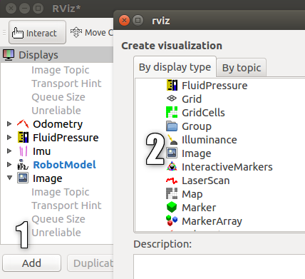
And add a new Display called “Image” in it:
A new display with a camera image will appear and ... the gazebo editor will fly out.
Unfortunately, when working on a virtual machine with a VMWare image, adding a broadcast from a virtual camera results in an error.
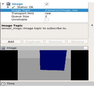
If the work is carried out not on a virtual machine, but on a real one, then we will get an image from a virtual camera in gazebo with an image of a column figure:
Now let's add IMU to the model.
The process of adding imu is similar to adding a camera.
First, open rosbots.gazebo.xacro and make
We will add this code, as well as the code for the added camera, within the tag
As it is not difficult to guess from the code, it will publish the data in the topic / imu / data.
Now, if you re-place the robot model in gazebo and execute the command:
in the neighboring terminal, you can see the topic with imu data among others:

You can also take a look at what he publishes by running the command:

In short, imu publishes the following information:
Add to rosbots.gazebo.xacro everything is also within the tag
This code will determine additional parameters of the robot: friction coefficients for wheels, colors in gazebo, contact sensor. The contact sensor will be triggered immediately after the robot bumper touches the obstacle.
Now restart gazebo, place the model, and in rviz add imu display as before, add display with a camera:

If everything went well, then we will see that imu is posting in a topic.
Finally, we control the robot in the simulation and see how the data changes with imu:
1st terminal:
2nd:
3rd:
Possible errors during operation :
1. The robot model does not appear in gazebo (Package [rosbots_description] does not have a path) - close gazebo, execute source devel / setup.bash in the terminal, restart gazebo.
2.
Possible solution (not tested):
Previous posts in the series:
1. Part 4
2. Part 3
3. Part 2
4. Part 1
Last time, the following goals were achieved:
- visualize the robot by creating an xacro file containing the urdf description of the robot;
- create two launch files, one of which allows you to place the robot in the editor-simulator Gazebo;
- control the robot in the Gazebo simulator from the keyboard.
In this post, we will arrange the project in the form of xacro modules so that it becomes more readable (earlier, for clarity, we pushed the entire description into one xacro file). Add a virtual video camera and imu. Let’s see how to add gazebo to foreign objects.
First, let's check whether the terminal works on roaming through the ROS system using the roscd commands:
roscd rosbots_description/launch
If it does not work, then go to the folder with catkin_ws and execute the command:
source devel/setup.bash
Now let's go to the folder with the description of the robot:
roscd rosbots_description/launch
In the previously created spawn.launch file, the following was indicated:
<param name="robot_description" command="cat '$(find rosbots_description)/urdf/rosbots.xacro'" />
The cat command was used to load the contents of rosbots.xacro into the robot_description parameter.
To take full advantage of the xacro command format, the code needs to be slightly corrected. Replace the above line with the following:
<param name="robot_description" command="$(find xacro)/xacro.py '$(find rosbots_description)/urdf/rosbots.xacro'" />
Now the system will use xacro.py to execute rosbots.xacro.
The same changes will be required for the second launch file - rviz.launch.
Change
<param name="robot_description" command="cat '$(find rosbots_description)/urdf/rosbots.xacro'" />
on
<param name="robot_description" command="$(find xacro)/xacro.py '$(find rosbots_description)/urdf/rosbots.xacro'"/>
Check that everything works with the new syntax.
First, look at the model in the rviz editor:
roslaunch rosbots_description rviz.launch
Then, closing rviz, check in gazebo.
1st terminal:
roslaunch gazebo_ros empty_world.launch
2nd:
roslaunch rosbots_description spawn.launch
* You can see the messages
yellow color
xacro: Traditional processing is deprecated. Switch to --inorder processing! To check for compatibility of your document, use option --check-order. For more infos, see http://wiki.ros.org/xacro#Processing_Order xacro.py is deprecated; please use xacro instead
They do not give the weather, so you can not pay attention.
So, everything works as before, only now the xacro format is used.
What does he give? This format allows you to reorganize the code. As the project grows, this will help to better navigate in the future.
Working with xacro
Now it's time to split rosbots.xacro into its constituent parts and take advantage of xacro.
Move everything about the gazebo editor (gazebo tags) from rosbots.xacro to a new file.
Create the rosbots.gazebo.xacro file in the urdf folder:
nano rosbots.gazebo.xacro
And put the code there:
rosbots.gazebo.xacro
<?xml version="1.0"?> <robot xmlns:xacro="http://www.ros.org/wiki/xacro" name="rosbots" > <gazebo> <plugin name="differential_drive_controller" filename="libgazebo_ros_diff_drive.so"> <legacyMode>false</legacyMode> <alwaysOn>true</alwaysOn> <publishWheelTF>true</publishWheelTF> <publishTf>1</publishTf> <publishWheelJointState>true</publishWheelJointState> <updateRate>100.0</updateRate> <leftJoint>wheel_left_joint</leftJoint> <rightJoint>wheel_right_joint</rightJoint> <wheelSeparation>1.1</wheelSeparation> <wheelDiameter>0.52</wheelDiameter> <wheelAcceleration>1.0</wheelAcceleration> <torque>20</torque> <commandTopic>/part2_cmr/cmd_vel</commandTopic> <odometryTopic>odom</odometryTopic> <odometryFrame>odom</odometryFrame> <robotBaseFrame>base_link</robotBaseFrame> </plugin> </gazebo> </robot>
The same code within the tag
<gazebo> </gazebo>
delete from the rosbots.xacro file.
Now we will bind the newly created file to rosbots.xacro. From somewhere, the same information about the gazebo component of rosbots.xacro should be received!
Accordingly, add to rosbots.xacro:
<xacro:include filename="$(find rosbots_description)/urdf/rosbots.gazebo.xacro" />
Insert this line after the line with the tag
<robot>
. Now the beginning of the file looks like this:
<robot name="rosbots" xmlns:xacro="http://www.ros.org/wiki/xacro"> <xacro:include filename="$(find rosbots_description)/urdf/rosbots.gazebo.xacro" />
Check again that everything works in the new format:
1st terminal:
roslaunch gazebo_ros empty_world.launch
2nd:
roslaunch rosbots_description spawn.launch
Thus, for the user, everything remains in place in terms of launching the model in the simulation, the commands are the same.
Add new sensors
Now that the project has taken a more or less structured look, we’ll attach additional sensors.
In order not to clutter the robot heavily with “body kits”, we add only two sensors: a camera and imu (inertial measuring module or gyroscope).
For these purposes, you will need to correct the rosbots.xacro and rosbots.gazebo.xacro files.
Let's start with the camera and the rosbots.xacro file. In order for everything to work out, for the sensor you need to add:
- communication (link). It will be represented by a dae file.
- joint, which will attach the camera to the body of the robot.
In another file - rosbots.gazebo.xacro - we will add:
- a plugin that will detect the link created above as a sensor.
Let's place in rosbots.xacro within the tag (for convenience, you can add it at the end):
rosbots.xacro
<joint name="camera_joint" type="fixed"> <origin xyz="0.49 -0.03 0.75" rpy="0 0.21 0" /> <parent link="base_link"/> <child link="camera_link" /> </joint> <link name="camera_link"> <visual> <geometry> <mesh filename="package://rosbots_description/meshes/camera.dae" scale="4.0 4.0 4.0"/> </geometry> <origin xyz="0.0 0 0" rpy="0 0 0"/> </visual> <collision> <geometry> <mesh filename="package://rosbots_description/meshes/camera.dae" scale="4.0 4.0 4.0"/> </geometry> <origin xyz="0.0 0 0" rpy="0 0 0"/> </collision> </link>
The code above adds link and joint to our camera, allowing it to be visualized.
Check this out.
1st terminal:
roslaunch gazebo_ros empty_world.launch
2nd:
roslaunch rosbots_description spawn.launch
If everything is correct, then you can see the added camera on the robot (white):
It seems that everything is simple. However, it must be understood that only camera visualization has been added. How this camera will behave in the world of physical things is not yet clear. Her behavior is undefined. The camera is not yet able to take photos or shoot videos.
It's time to work on the file with gazebo.
Add to
rosbots.gazebo.xacro
inside tags
add:
<robot> </robot>
add:
<gazebo reference="camera_link"> <sensor type="camera" name="camera1"> <update_rate>30.0</update_rate> <camera name="head"> <horizontal_fov>1.04</horizontal_fov> <image> <width>320</width> <height>240</height> <format>R8G8B8</format> </image> <clip> <near>0.1</near> <far>50</far> </clip> </camera> <plugin name="camera_controller" filename="libgazebo_ros_camera.so"> <alwaysOn>true</alwaysOn> <updateRate>0</updateRate> <cameraName>camera1</cameraName> <imageTopicName>image_raw</imageTopicName> <cameraInfoTopicName>camera_info</cameraInfoTopicName> <frameName>camera</frameName> <hackBaseline>0.07</hackBaseline> <distortionK1>0.0</distortionK1> <distortionK2>0.0</distortionK2> <distortionK3>0.0</distortionK3> <distortionT1>0.0</distortionT1> <distortionT2>0.0</distortionT2> </plugin> </sensor> </gazebo>
As it’s easy to guess in the code, we determined the camera parameters:
- update_rate: how often will the data arrive
- width / height: resolution of pictures. In this case, 320x240.
- format: video format (R8G8B8).
- imageTopicName: the name of the topic where the data will be sent
- frameName: link-link to which the camera will be attached.
Now everything is ready for both visualizing the camera and its simulation.
If you now restart the simulation and see a list of topics, you can see that among them the topics generated by the camera have been added:
rostopic list
/rosbots/camera1/camera_info /rosbots/camera1/image_raw /rosbots/camera1/image_raw/compressed /rosbots/camera1/image_raw/compressed/parameter_descriptions /rosbots/camera1/image_raw/compressed/parameter_updates /rosbots/camera1/image_raw/compressedDepth /rosbots/camera1/image_raw/compressedDepth/parameter_descriptions /rosbots/camera1/image_raw/compressedDepth/parameter_updates /rosbots/camera1/image_raw/theora /rosbots/camera1/image_raw/theora/parameter_descriptions /rosbots/camera1/image_raw/theora/parameter_updates /rosbots/camera1/parameter_descriptions /rosbots/camera1/parameter_updates
There is a whole arsenal of topics! But, as a rule, not all of them are used so often except the first three.
Image in rviz from gazebo simulator
* here it is necessary to make a reservation that in the current configuration of the image for VMWare Workstation gazebo crashes when trying to start broadcasting to rviz from a virtual video camera. A possible solution is indicated at the end of the post in the error section.
For clarity, when working with the camera in the simulation, run rviz and place some object in front of the robot.
To do this, you first need the object itself, which will be added to gazebo.
Download the object.urdf file and put it in ~ / catkin_ws / src /
Let's run it.
1st terminal:
roslaunch gazebo_ros empty_world.launch
2nd (place the models):
rosrun gazebo_ros spawn_model -file /home/pi/catkin_ws/src/object.urdf -urdf -x 1 -y 0 -z 1 -model my_object
roslaunch rosbots_description spawn.launch
In the simulation we get the following picture:
A robot model and a post that was also added as a model.
Items can be added to the gazebo editor in a simpler way from the tab inside the insert editor:
Now let's see what the robot sees.
Without closing the two previous terminals, run rviz with the description of the robot:
roslaunch rosbots_description rviz.launch
And add a new Display called “Image” in it:
A new display with a camera image will appear and ... the gazebo editor will fly out.
Unfortunately, when working on a virtual machine with a VMWare image, adding a broadcast from a virtual camera results in an error.
If the work is carried out not on a virtual machine, but on a real one, then we will get an image from a virtual camera in gazebo with an image of a column figure:
Now let's add IMU to the model.
IMU (gyroscope)
The process of adding imu is similar to adding a camera.
First, open rosbots.gazebo.xacro and make
the code
<gazebo> <plugin name="gazebo_ros_imu_controller" filename="libgazebo_ros_imu.so"> <!-- <robotNamespace></robotNamespace> --> <topicName>imu/data</topicName> <serviceName>imu/service</serviceName> <bodyName>base_link</bodyName> <gaussianNoise>0</gaussianNoise> <rpyOffsets>0 0 0</rpyOffsets> <updateRate>30.0</updateRate> <alwaysOn>true</alwaysOn> <gaussianNoise>0</gaussianNoise> </plugin> </gazebo>
We will add this code, as well as the code for the added camera, within the tag
<robot></robot>
As it is not difficult to guess from the code, it will publish the data in the topic / imu / data.
Now, if you re-place the robot model in gazebo and execute the command:
rostopic list
in the neighboring terminal, you can see the topic with imu data among others:
You can also take a look at what he publishes by running the command:
rostopic echo /imu/data -n1
In short, imu publishes the following information:
- orientation: the orientation of the robot along the x, y, z, and w axes.
- angular_velocity: angular speed of the robot.
- linear_acceleration: linear acceleration.
There is a small touch
.Add to rosbots.gazebo.xacro everything is also within the tag
the code
<gazebo reference="wheel_left_link"> <mu1>1.0</mu1> <mu2>1.0</mu2> <kp>1000000.0</kp> <kd>100.0</kd> <minDepth>0.001</minDepth> <maxVel>1.0</maxVel> </gazebo> <gazebo reference="wheel_right_link"> <mu1>1.0</mu1> <mu2>1.0</mu2> <kp>1000000.0</kp> <kd>100.0</kd> <minDepth>0.001</minDepth> <maxVel>1.0</maxVel> </gazebo> <gazebo reference="base_link"> <material>Gazebo/Blue</material> <mu1>0.3</mu1> <mu2>0.3</mu2> <sensor type="contact" name="bumpers"> <always_on>1</always_on> <update_rate>50.0</update_rate> <visualize>true</visualize> <contact> <collision>base_footprint_collision_base_link</collision> </contact> </sensor> </gazebo> <gazebo reference="camera_link"> <mu1>0.2</mu1> <mu2>0.2</mu2> </gazebo>
This code will determine additional parameters of the robot: friction coefficients for wheels, colors in gazebo, contact sensor. The contact sensor will be triggered immediately after the robot bumper touches the obstacle.
Now restart gazebo, place the model, and in rviz add imu display as before, add display with a camera:
If everything went well, then we will see that imu is posting in a topic.
Finally, we control the robot in the simulation and see how the data changes with imu:
1st terminal:
roslaunch gazebo_ros empty_world.launch
2nd:
roslaunch rosbots_description spawn.launch
roslaunch rosbots_description rviz.launch
3rd:
rosrun teleop_twist_keyboard teleop_twist_keyboard.py /cmd_vel:=/part2_cmr/cmd_vel
Possible errors during operation :
1. The robot model does not appear in gazebo (Package [rosbots_description] does not have a path) - close gazebo, execute source devel / setup.bash in the terminal, restart gazebo.
2.
gzserver: /build/ogre-1.9-mqY1wq/ogre-1.9-1.9.0+dfsg1/OgreMain/src/OgreRenderSystem.cpp:546: virtual void Ogre::RenderSystem::setDepthBufferFor(Ogre::RenderTarget*): Assertion `bAttached && "A new DepthBuffer for a RenderTarget was created, but after creation" "it says it's incompatible with that RT"' failed. Aborted (core dumped)
Possible solution (not tested):
https://bitbucket.org/osrf/gazebo/issues/1837/vmware-rendering-z-ordering-appears-random
All Articles