ShIoTiny and the surrounding world: connecting sensors to binary inputs, contact bounce and other issues

Key points or what this article is about
Another article about ShIoTiny - a visually programmable controller based on the ESP8266 chip. The article describes the features of connecting sensors of various types to the binary inputs of the ShIoTiny controller. In addition, there are answers to a number of popular questions from readers of previous articles in the series.
Previous Series Articles
ShIoTiny: small automation, the Internet of things, or “six months before the holidays”
ShIoTiny: nodes, links and events or features of drawing programs
ShIoTiny: wet room ventilation (example project)
Binary firmware, controller circuitry and documentation
Intro or answers to questions
All my articles on the subject of ShIoTiny , except the first, were born from questions from readers who risked trying my firmware.
The fact is that to answer in detail and to all at once - I do not have the opportunity. A hobby is a hobby and it is rare for anyone to devote as much time to it as work, household chores or children. Nor can I. And the questions from the letters can essentially be reduced to several. Therefore, it is easier to write an article that covers several issues in detail than to write a dozen letters.
Many questions concern how to connect sensors of various types and how to work with them. This is not surprising: working with output relays is quite simple. And what they just do not want to connect to the inputs! There are plenty of options. This article is dedicated to this article and will most likely be devoted to the following: a very broad topic - the connection of sensors.
But, before moving on to the biography of the amazing world of sensors, I will allow myself to use the Habr as a media to answer the most popular questions that they ask me in letters.
Answers to the most popular questions of readers
Probably the most popular question is “ why don’t you support PWM / DS1821 / RTC ... and so on? ". I answer. Because when I designed ShIoTiny, I didn’t need it. As for PWM, there is simply nowhere to put it on the ShIoTiny board. There are no legs left to connect RTC . And so on. But if the project develops successfully enough - I will make another device with the same programming ideology, but with a different set of peripherals. Of course, I will support some additional chips in ShIoTiny, as I supported, for example, just yesterday the DS1820 / 22 temperature sensor. But it is impossible to embrace the immensity and to shove the inedible. The controller memory, like my time, is not unlimited.
The next most popular question is: “ Do you plan to mass-produce ShIoTiny? ". I will answer in detail. At the moment I have a few more boards and if anyone is interested - write, I will send. If they remain by then, of course. Serially (meaning 50-100 pieces), again, at the moment I do not plan to release it. There is simply no such demand, and letting us say 50 boards is not so easy for a hobby and will cost me a lot. There will be many who want to get a ready fee - the situation may change. So if not everything, then a lot depends on the opinion and desire of society.
Another question asked very often: “ where to get the source? ". I answer. Nowhere else. For some reason, I can’t post them yet and I don’t know if I can in the foreseeable future.
And finally, questions on MQTT and UDP multicast . On these issues, I hope to make a separate article, because there are many features. Something about MQTT is in the previous article about the ventilation system, but everything is described there in general terms. And yet - read the instructions. There are many answers, although this is still a draft.
This concludes with popular questions and finally deals with what this article was written for - the amazing, beautiful, frightening and mysterious world of sensors.
Sensor - what is it and why is it?
Any inscription in an unknown language is just a complex pattern for someone who has never seen letters or hieroglyphs. There are no paintings for the blind. For the deaf, music. Why am I? And to the fact that information is a conditional display of an object or phenomenon on some material medium. Information without a material carrier does not exist. As well as information does not exist without someone who is able to understand it.
Therefore, if we want our ShIoTiny not to be “blind,” “deaf,” and “illiterate,” we must teach him to “ perceive ” and “ understand ” information about the world around him and make decisions on how to manage it us equipment.
Information about the world exists in a wide variety of representations and on various material carriers: air vibrations - sound and photon flux - light; the concentration of water vapor in the air and the temperature of the earth; the presence or absence of mass and its magnitude. And so on. All this can carry for us the information we need to make decisions.
But our ESP8266 microcontroller - the basis of ShIoTiny - understands only two types of information - digital binary signals 0V - 3V and analog signals in the range from 0V to 1V .
Therefore, we need “ translators ” from the language of a particular physical phenomenon or physical quantity to the language of electrical signals that are understandable to the ESP8266 microcontroller. Such " translators " are called sensors .
Strictly speaking, in our case, the sensor is a technical tool that converts information about the surrounding world into electrical signals that are understandable to the electronic components of the ShIoTiny controller.
Sensors are different. There are thousands and darkness. But if you start to understand, then everything is not so scary. Firstly , we are only interested in sensors that generate an electrical signal at the output. Secondly , we will limit ourselves only to popular types of sensors. And thirdly , in practice there are not so many types of signals generated by sensors.
From the "first" - everything is clear. It is physically impossible to connect a sensor directly to ShIoTiny that provides information in mechanical, hydraulic or pneumatic form.
With "secondly" - everything is also clear. It is unlikely that anyone will connect specific fast-particle traps or pH meters in a molten radioactive lithium to ShIoTiny . Well, if anyone does, I think that his qualifications are much higher than mine and he most likely will not need this article. But the temperature of water or air, the pressure of air or water, humidity, light, liquid level or the condition of the door (open-closed) - all this can very well be measured by the ShIoTiny controller in household control systems.
We will deal with the "third". What electrical signals are usually output from common types of sensors? Three main types of signals at the outputs of the sensors can be distinguished:
Binary signals . That is, signals that have only two levels - logical 0 or logical 1. Electrical parameters are not important - they can always be converted to the desired levels.
Analog signals . That is, current or voltage, varying depending on the measured parameter in a given range of values.
Digital signals . These are sensors that communicate with microcontrollers using a specific protocol.
Here, perhaps, are all the options that can be connected to ShIoTiny . Of course, there are also sensors with a frequency output, a phase output, and sensors with all kinds of exotic output signals. But since it’s impossible to connect them directly to ShIoTiny, we won’t talk about them now.
Binary inputs ShIoTiny
Let's start with the simplest - with the ShIoTiny binary inputs. They are indicated by Input1 , Input2, and Input3 . Since these inputs are absolutely identical, we will consider the input Input1 . Everything that is said about this input is just as true for the other two binary inputs - Input2 and Input3 .
The ShIoTiny binary input circuit is shown in the figure. Immediately make a reservation, the circuit with a small flaw - it was necessary to connect a 10K resistor to a 1K resistor. But this does not affect the operation of the device and it is wonderful. So, why are there so many elements in a binary input circuit? Such a question was also asked to me. I will try to answer it.

Binary input in ShIoTiny works on “ dry ” and “ wet ” contacts. In addition, the circuit provides overvoltage protection (that is, if 5 Volts instead of 3 Volts, for example, gets to Input1 , for example).
Binary input protection
Overvoltage protection, which is made on all binary inputs of ShIoTiny , of course will not save the controller from burnout, if a voltage of ~ 220V is applied to its input. But from getting to the inputs Input1,2,3 + 5V or even + 12V - this protection completely saves.
Such protection works very simply and can be applied not only with the ESP8266 , but also with other microcontrollers.
Consider two options for the protection: when applying + 5V and -5V voltage to the neutral wire ( ground ) to the Input1 input.
When the voltage at the input Input1 is normal - the protective diodes D1 and D2 are closed, since they are turned on in the opposite direction.
As soon as the voltage at Input1 exceeds + 3V (for example, we shorted Input1 to + 5V ), the D1 diode opens and pulls the GPIO controller's input to + 3V , preventing the voltage at the GPIO ESP8266 from rising above 3V . Actually, the voltage will be slightly higher than 3V (3.2V or 3.3V) - but it does not matter. The microcontroller input will not burn and this is the main thing.
As soon as the voltage at Input1 becomes negative (for example, we shorted the input to -5V ), then the D2 diode opens and pulls the Input1 to ground 0V , not letting the voltage at the GPIO ESP8266 input drop below 0V . Actually, the voltage will be slightly lower than 0V (-0.2V or -0.3V) - but this is again not important. The microcontroller input will not burn.
Resistor 1K is a current limiter so that there is no short circuit during protection operation. The currents through it are small. For example, in our example, if we apply Input1 + 5V to the input, then the current through the 1K resistor will be about 2mA . With a negative voltage of -5V at the input Input1, the current through the 1K resistor will be about 5mA .
If someone does not understand why the diodes open and close, then I recommend reading the book "Electronics Step by Step" by R. A. Svorenya . On the Internet it is, for example, here . I especially advise beginners - the language of this book is simple and there are plenty of examples.
What are the contacts
So, with the protection sorted out. Let's move on to another fundamental issue - connecting the ShIoTiny binary input to binary sensors.
As we have already said, binary sensors are sensors whose output has two states - zero and one. But this is logical. And physically there can be two options for the binary sensor outputs: “ dry contact ” and “ wet contact ”. Consider what it is and what it is eaten with.
A “ dry contact ” is a contact that does not have its own voltage source. That is, just any two metal conductors that can be shorted together and open them. This definition includes the mass of sensors - buttons, switches, float sensors for liquid level, reed switches (magnetic field sensors) and so on. On electrical circuits, normally open “ dry contacts ” are usually indicated as shown in the figure.
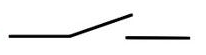
Normally open - this means open when there is no external influence - the button is not pressed, the switch is not turned on, the reed switch does not have a magnet nearby ...
There are also normally closed “ dry contacts ”. On electrical circuits, they are usually indicated as shown in the figure.
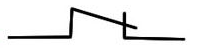
In contrast to normally open, normally closed " dry contacts " in the absence of external influences are closed.
Both those and other " dry contacts " can be safely connected to the inputs Input1,2,3 controller ShIoTiny . Sensors with a dry contact type output are connected to the ShIoTiny binary inputs as shown in the figure.

If the “ dry contact ” of Input1 is closed, then the voltage of approximately zero volts is applied to the controller input (more precisely - 0.3 Volts due to an error in the circuit), since the “ dry contact ” closes the controller input to ground through a divider formed by 1K and 10K resistances. In this case, the node Input1 will set the unit to output.
Conversely, if the dry contact of Input1 is open, then about three volts are supplied to the controller input, since the controller input is pulled to the supply voltage through a 10K resistor. In this case, the node Input1 will set zero on its output.
All this detailed description is for the curious. The bottom line is that if we connected a sensor with an output of type “ dry contact ” to Input1 , then when the contact is open, the output of the Input1 node will be zero, and when the contact is closed, the output of the same node will be one. Similarly for inputs and nodes Input2 and Input3 .
Let's move on to wet contacts .
A “ wet contact ” is a contact that has its own voltage source in at least one of its positions. For example, the output of another controller or logic circuit; light bulb power line and so on. There may be plenty of options. But almost all of them directly or with the help of several details allow matching binary inputs Input1,2,3 with the device output - “ wet contact ”.
Let's start with the simplest - matching the input Input1 with the output of the sensor or microcircuit type " open collector " or " open drain ".
In fact, in our case , this circuit is completely analogous to connecting a sensor with a dry contact output . Only the role of the contact is performed by the transistor.
The scheme of such a connection is shown in the figure. The essence of the concept of “ open collector ” or “ open drain ” is that the emitter (or source ) of the output transistor is connected to the “ ground ” (often right inside the microcircuit), and the collector (or drain ) is connected to the “leg” of the microcircuit and more to nothing.
How this scheme works is understandable for a novice (not an imaginary gas, but a person!). As soon as the transistor inside the microcircuit opens, it closes the input Input1 to ground and then everything works by analogy with a “ dry ” contact.

Unfortunately, not all microcircuits and sensors have such a wonderful output with an open collector or drain. Many, if not most chips and sensors have an active output. This means that when we have a logical unit at the output, the output is “pulled up” to the supply voltage, and when a logical zero, the output is “pulled up” to the ground. The output of such a chip is shown in the figure below. Of course, everything is simplified.

What should we do if the microcircuit or sensor we want to connect to Input1 has such an active output?
There are two options here and they depend on the value of the supply voltage of the microcircuit or Vcc sensor.
If the supply voltage of the chip or Vcc sensor is the same as that of the ESP8266 (that is, 3 Volts), then you can simply connect this output to the input Input1 , which is actually shown in the previous figure.
But what if the sensor or microcircuit's power supply is + 5V or + 12V ? In our case, you can do quite simply by turning on the Schottky diode, as shown in the figure below.
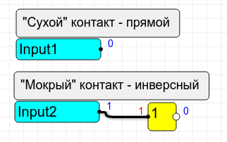
And one more nuance: all circuits with a “ wet ” contact give us an inverse signal . That is, when the logic unit is at the output of the sensor or microcircuit, the Input1 node will set the output to zero. And vice versa. But this is corrected programmatically - just insert the inverter node into the circuit. All this is shown in the figure.
That, in fact, is all the basic things you need to know about connecting sensors to the binary inputs Input1,2,3 .
Of course, theoretically there may be other options, but I showed the simplest and most common ways to connect sensors with dry contact outputs and low-voltage active outputs.
Thrill of contact
Contacts tremble. Not from fear of the creator of the device, but from the fact that they are resilient. When you press the button, the contacts can close-open 5-7 times before being stably closed. The same phenomenon occurs when the buttons are released. And this phenomenon is called - " bounce of contacts ."
Contact bounce - the curse of all mechanical contact sensors - switches, buttons, reed switches and so on. The unpleasant chatter is that it causes false clicks or false releases of a button or contact.
There are several ways to deal with this unpleasant phenomenon. Probably the oldest way to fight is trigger . With this method, a button with a switching contact and a regular RS-trigger are used, which are turned on according to the scheme, as shown in the figure.
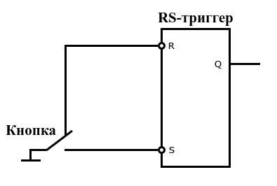
How it works? Very simple. A trigger has two states. While the button is closed to the input R of the trigger, the output Q of the trigger is set to zero.
We pressed the button - until the middle contact of the button touched the bottom - nothing changes, the output of the trigger is zero. As soon as the middle contact of the button touched the lower contact of the same button and closed the input of trigger S to ground, one appears at the output of the trigger. And this unit remains while contacts "rattle". Indeed, to switch the trigger output back to zero, it is necessary that the trigger input R is shorted to ground! This scheme works exactly the same way when you release the button.
Can we make such a circuit on ShIoTiny ? No problem! In the figure, it is shown.
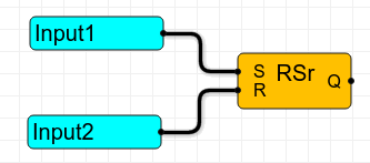
But spend two of their three inputs on one sensor ?! Moreover, not all sensors have a switching contact!
No, we will go the other way, as bequeathed to everyone, the brilliant theoretician V.I. Ulyanov!
The second, and probably most common today, way to deal with contact bounce is a software filter .
What is behind these clever words? And again - nothing complicated. Imagine that we will not respond to “short” changes in the state of contacts. For example, if we read zero from the button, then for short (say, the duration is less than 0.3 sec) unit bursts, we we will hammer stop reacting. And only when we have a button for 0.3 seconds will continuously issue a unit - we will respond to this. The same thing when changing the state of the button from one to zero.
That is, in essence - we will pass the transition process by filtering out short pulses. Thus, we will protect ourselves from bounce and false positives. And you will not need to have a switching contact and RS-trigger!
How do we do this in practice? In ShIoTiny there is a filter node that is used to eliminate chatter is connected as shown below.
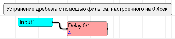
The Delay0 / 1 filter in this case ignores all pulses that have a duration of less than 0.4 sec .
Of course, for different contacts and different sensors, the duration of bounce will be different. But I think you yourself will decide what length of the filter delay you need.
Conclusion
In conclusion, I would like to apologize to those to whom this article seemed unnecessarily detailed - remember that there are a lot of people on the hub who are not as wise as you are experienced.
In the next article, we will examine the connection of sensors with an analog output signal to the ADC input.
As always, suggestions, wishes, questions, typos, etc., by e-mail: shiotiny@yandex.ru
All Articles