Project objectives
Somehow it turned out that I built my house, a skeleton. In my luxury aul there is no gas and is not expected in the near future, therefore I chose a skeleton - everything else, for me, it would be very expensive to heat with electricity. Well, also because it is one of the cheapest technologies.
Ok, I threw pipes around the house, hung up batteries, a boiler, it seemed warm, but something was wrong.
Having listened to myself, I realized that this is a toad that I do not like, that while I am not at home (12-16 hours a day), the heating works. And it might not work, turn on only before arrival, since the skeleton has a slight inertia and allows you to quickly raise the temperature. The same situation when somewhere for a long time to leave home. Well, in general, running, twisting the handle of the boiler with changes in temperature on the street is somehow not kosher.
It became clear that without automation, nowhere, the boiler is the simplest one, but it has contacts for connecting an external control relay. Of course, you could immediately buy a boiler with all the necessary functions, but for me, such boilers are somehow inhumane. Plus I wanted to squat with brains, pee something for the soul, learn a little C, albeit in the arduino version.
Actually about the requirements:
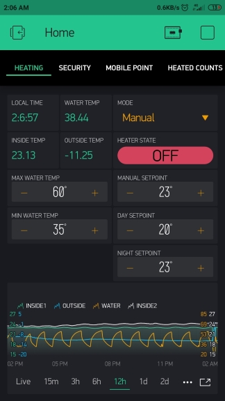
- setpoint temperature control
- control of the temperature of the coolant depending on the temperature outdoors or manually
- time zones with different settings, colder by day, hotter by night
- automatic mode, with auto day-night transition
- manual mode, no auto transitions, for the weekend
- non-automatic mode, where you can manually set any coolant temperature and turn on / off the boiler
- heating control locally, from buttons and screen and via website / mobile application
It was at the beginning, and then I suffered and added:
- street lamp control (LED spotlight)
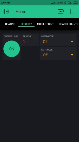
- alarm system based on motion sensor, siren and street lamp
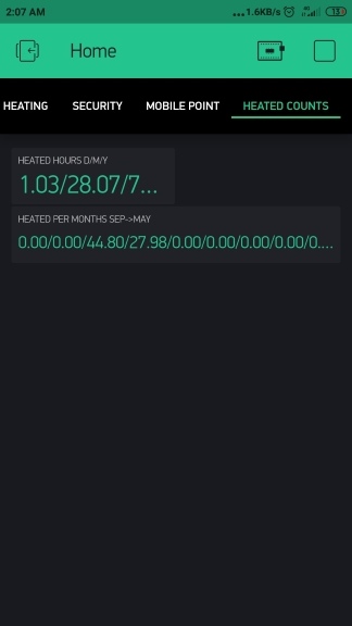
- metering the energy consumed by the boiler per day / month / year + for each month of the year
- alarm mode only by slow flashing of a lamp
- signaling mode by fast blinking of a lamp and short beeps of a siren
- signaling mode by fast blinking of a lamp and constant howl of a siren
The purpose of this article is to share experience, describe something in Russian that I could not find on the Internet. I think this article will be useful to beginner Arduino do-it-yourselfers who are already a little familiar with programming, as absolutely basic things I did not describe. I tried to write the code as clear as possible, I hope I succeeded.
What was in the beginning
Initially, the project was implemented on a wild bunch of Arduino Nano + ESP8266, but ESP is not as a shield, but as a separate device. Why is that? Yes, because I already had all this, but I didn’t have money from the word at all, so I didn’t want to buy new iron in principle. Why is ESP not like a shield? Now I don’t even remember.
Arduino steered all the processes because it had the required amount of GPIO, and ESP sent all the data to the Blynk server, because it knew the Internet and did not have enough GPIO. They connected themselves through UART, and sent JSON with data to each other. The scheme is unusual, but it worked for a year with almost no complaints. Anyone interested can see the codec .
I’ll make a reservation right away, I didn’t know much how to program (and now I would like to do it better), therefore it is better for pregnant women and children not to watch. In addition, everything was written in the Arduino IDE, it will not be remembered by night, which greatly limited in terms of refactoring, everything is very primitive there.
Iron
So, a year has passed, finances allowed to buy ESP32 devkit v1, which has enough GPIO, can access the Internet and generally a super controller. In addition to jokes, I liked her very much at the end of the work.
Iron list:
- ESP32 devkit v1 noname China
- 3 temperature sensors DS18B20, temperature inside the house, outside and the temperature of the coolant in the pipes
- block of 4 relays
- pir sensor HC-SR501
I won’t draw a scheme, I think everything will be clear from the macros with the names of the pins.
Why FreeRTOS and Arduino Core
A bunch of libraries are written on Arduino, in particular, the same Blynk, so you won’t get away from Arduino Core.
FreeRTOS because it allows you to organize the work of a small piece of iron similar to the work of a full-fledged industrial controller. Each task can be moved into its own task, stopped, started, created when necessary, deleted - all this is much more flexible than writing a long tangle of Arduino code, when in the end everything is done in turn in the loop function.
When using FreeRTOS, each task will be executed at a strictly specified time, if only the processor power is enough. On the contrary, in Arduino all the code is executed in one function, in one thread, if something slows down, the rest of the tasks will be delayed. This is especially noticeable when managing fast processes, in this project this blinking of a flashlight and the siren beeping will be discussed below.
About logic
About FreeRTOS tasks
Link to the entire codec of the project .
So, when using FreeRTOS, the setup function plays the role of the main function, the entry point to the application, FreeRTOS tasks (hereinafter tasks) are created in it, the loop function can not be used at all.
Consider a small task for calculating the coolant temperature:
void calculate_water_temp(void *pvParameters) { while (true) { if (heating_mode == 3) {} else { if (temp_outside > -20) max_water_temp = 60; if (temp_outside <= -20 && temp_outside > -25) max_water_temp = 65; if (temp_outside <= -25 && temp_outside > -30) max_water_temp = 70; if (temp_outside <= -30) max_water_temp = 85; } vTaskDelay(1000 / portTICK_RATE_MS); } }
It is declared as a function that must take _void pvParameters
, an endless loop is organized inside the function, I used while (true)
.
A simple temperature calculation is vTaskDelay(1000 / portTICK_RATE_MS)
(if the operating mode allows) and then the task is euthanized by vTaskDelay(1000 / portTICK_RATE_MS)
for 1 second. In this mode, it does not consume processor time, the variables that the task worked with, in other words, the context, is saved on the stack to get them out of there when the time comes.
Next task must be created in setup. This is done by calling the xTaskCreate
method:
xTaskCreate(calculate_water_temp, "calculate_water_temp", 2048, NULL, 1, NULL);
There are many arguments, but for us, calculate_water_temp is significant - the name of the function containing the task code and 2048 is the stack size in bytes.
The size of the stack initially set everyone to 1024 bytes, then I calculated the desired method by typing, if the controller started to fall with a stack overflow (as can be seen from the output in uart), I just increased the size of the stack by 2 times, if it didn’t help, by 2 times and so on until it works. Of course, this does not save memory too much, but ESP32 has enough of it, in my case you could not bother with this.
You can also specify a handle for task - a handle with which you can control task after creation, for example - delete. This is the last NULL in the example. A handle is created like this:
TaskHandle_t slow_blink_handle;
Next, when creating a task, a pointer to the xTaskCreate
passed to the xTaskCreate parameter:
xTaskCreate(outside_lamp_blinks, "outside_lamp_blynk", 10000, (void *)1000, 1, &slow_blink_handle);
And if we want to remove the task, we do this:
vTaskDelete(slow_blink_handle);
How this is used can be seen in the panic_control panic_control
code.
FreeRTOS Mutex Pros
Mutex is used to eliminate conflicts between tasks when accessing resources such as uart, wifi, etc. In my case, I needed mutexes for wifi and access to flash memory.
Create a link to the mutex:
SemaphoreHandle_t wifi_mutex;
In setup
create a mutex:
wifi_mutex = xSemaphoreCreateMutex();
Further, when we need access to the task resource, it takes the mutex, thereby letting the rest of the tasks know that the resource is busy and there is no need to try to work with it:
xSemaphoreTake(wifi_mutex, portMAX_DELAY);
portMAX_DELAY
- wait indefinitely until the resource and the mutex are freed by other tasks, all this time the task will sleep.
After working with the resource, we give the mutex so that others can use it:
xSemaphoreGive(wifi_mutex);
You can see the code in more send_data_to_blynk
in the send_data_to_blynk send_data_to_blynk
.
In practice, the non-use of mutexes was not noticeable during the operation of the controller, but with JTAG debug, errors constantly disappeared that disappeared after using mutexes.
Short description
get_temps
- receiving temperature from sensors, every 30 seconds, more often it is not necessary.
get_time_task
- get time from NTP servers. Previously, the time was obtained from the RTC module of the DS3231, but it began to fail after a year of work, so I decided to get rid of it at all. I decided that for me this does not have any special consequences, mainly time affects the switching of the heating time zone - day or night. If the Internet disappears during the operation of the controller, the time will simply freeze, the time zone will simply remain the same. If the controller turns off and after turning on there is no Internet, then the time will always be 0:00:00 - heating mode at night.
calculate_water_temp
- considered above.
detect_pir_move
- receiving a motion signal from the HC-SR501 sensor. The sensor forms a logical unit of + 3.3V when motion is detected, which is detected using digitalRead
, by the way, the pin for detection for this sensor should be pulled up to GND - pinMode(pir_pin, INPUT_PULLDOWN);
heating_control
- switching heating modes.
out_lamp_control
- control of a street lamp.
panic_control
- control siren and spotlight when motion is detected. To create the effect of sirens and flashing lights, separate tasks are used, outside_lamp_blinks
and siren_beeps
. When using FreeRTOS, flashing and beeps work simply perfectly, exactly at the intervals that are set, other tasks do not affect their work, because they live in separate streams. FreeRTOS guarantees that the code in the task will be executed at the specified time. When implementing these functions in the loop
everything worked not so smoothly, because influenced by the execution of other code.
guard_control
- control of guard modes.
send_data_to_blynk
- send data to the Blynk application.
run_blynk
- task for launching Blynk.run()
as required by the manual for using Blynk. As I understand it, this is required to obtain data from the application to the controller. In general, Blynk.run()
should be in a loop
, but I basically did not want to put anything there and made it a separate task.
write_setting_to_pref
- record settings and operating modes in order to catch them after a reboot. About pref will be described below.
count_heated_hours
- counting the operation time of the boiler. I did it simply, if the boiler is switched on at the moment of the task launch (once every 30 seconds), in the flash memory the value for the desired key is incremented by one.
send_heated_hours_to_app
- in this task the values are extracted and multiplied by 0.00833 (1/120 hours), the received hours of operation of the boiler are sent to the Blynk application.
feed_watchdog
- feed Watchdog. I had to write watchdog, because once every few days the controller could freeze. What it is connected with is not clear, there may be some kind of interference with the power supply, but using watchdog solves this problem. Watchdog timer 10 seconds, it’s okay if the controller is not available for 10 seconds.
heart_beat
- task with a pulse. When I pass the controller, I want to know that it works fine. Because on my board there is no built-in LED, I had to use the UART LED - install Serial.begin(9600);
and write a long string in UART. It works pretty well.
ESP32 NVS wear leveling
The following descriptions are rather crude, literally on the fingers, just to convey the essence of the issue. In details
Arduino uses EEPROM memory to store data in non-volatile memory. This is a small memory in which each byte can be written and erased separately, while flash memory is erased only by sectors.
ESP32 does not have an EEPROM, but there is usually 4 Mb flash memory in which you can create partitions for controller firmware or for storing user data. Sections for user data are of several types - NVS, FATFS, SPIFFS. It should be selected based on the type of data intended for recording.
Because all the recorded data in this project is of type Int, I chose NVS - Non-Volitile Storage. This type of partition is well suited for storing small, often overwritable data. To understand why, you should go a little deeper into the organization of NVS.
Like EEPROM and FLASH, there are restrictions on overwriting data, bytes in EEPROM can be overwritten from 100,000 to 1,000,000 times, and the FLASH sector is the same. If we write data once a second, then we get 60sec x 60 min x 24h = 86,400 times / day. That is, in this mode, the byte will last 11 days, which is a bit. After which the byte will be unavailable for writing and reading.
To smooth out this problem, the update()
put()
functions of the Arduino EEPROM library write data only when it changes. That is, you can write every second some settings and mode codes that change quite rarely.
NVS uses a different way to control wear leveling. As mentioned above, data in the flash sector can be written in parts, but only the entire sector can be erased. Therefore, data recording in NVS is carried out in a kind of journal, this journal is divided into pages that fit in one sector of flash memory. Data is recorded in pairs of key: value. In fact, it’s even easier than with EEPROM, because working with a meaningful name is easier than with an address in memory.
If you first write the value 1
to somekey
, and then write the value 2
to the same key, the first value will not be deleted, it will only be marked as deleted (Erased), and a new entry will be added to the log:
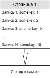
If you try to read data by somekey
last value of this key will be returned. Because Since the log is common, the values of different keys are stored next to each other as they are written.
The page has a status, Empty - empty, without entries, Active - data is currently being written to it, Full - is full, you cannot write to it. As soon as the page runs out of space, she’s from
Active goes to Full, and the next Empty page becomes Active.
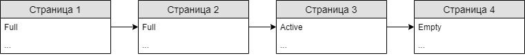
As far as I understand from the documentation on the Espressif website and various forums, page cleanup begins when free pages come to an end. To be more precise, according to this , erasing will occur when only 1 free page remains.
If the page needs to be cleared, then the current records (Non-Erased) are moved to another page, and the page is overwritten.
Thus, the write-erase operation for each particular page is quite rare, the more pages - the less often. Based on this, I increased the size of the NVS partition to 1 MB, at my recording rate this will last for 170 years, which in general is enough. About resizing the NVS section will be next.
For convenient work with NVS, ESP32 for Arduino Core has a handy Preferences library written, how to work with it is written here .
A bit about VisualGDB
As soon as I started working with the Arduino IDE, I was immediately surprised by the miserable functionality compared to Visual Studio. They say that VS is also not a fountain, although it suits me, but writing something over 50 lines in the Arduino IDE is painfully painful and painfully long. Thus, the question arose of choosing an IDE for development. Because I am familiar with VS, I settled on VisualGDB .
After the Arduino IDE, development for the ESP32 is simply a haven. What is the transition to definition, the search for calls in the project and the ability to rename a variable.
Changing the ESP32 Partition Table with VisualGDB
As mentioned above, the table can be changed with the ESP32 partition; we will consider how this can be done.
The table is edited as a csv file, by default VisualGDB writes the following table:
Name, Type, SubType, Offset, Size, Flags nvs, data, nvs, 0x9000, 0x5000, otadata, data, ota, 0xe000, 0x2000, app0, app, ota_0, 0x10000, 0x140000, app1, app, ota_1, 0x150000,0x140000, spiffs, data, spiffs, 0x290000,0x170000,
Here we see a section under NVS, two sections for applications, and a few more sections. Of the nuances, it can be noted that app0 (your application) should always be written at offset 0x10000, starting from the zero address, otherwise the bootloader will not detect it. Also, offsets should be selected so that the sections do not "overlap" each other. The partition table itself is written at offset 0x8000. As you can see, the size of the NVS in this case is 0x5000 - 20KB, which is not very much.
I modified the partition table as follows:
Name, Type, SubType, Offset, Size, Flags app0, app, ota_0, 0x10000, 0x140000, nvs, data, nvs, , 1M, otadata, data, ota, , 0x2000, spiffs, data, spiffs, , 0x170000,
Do not forget to add a grid before Name, if you use this table, you need this line to be considered a comment.
As you can see, the size of the NVS is increased to 1 MB. If you do not specify offsets, then the section will begin immediately after the previous one, so it is enough to indicate the offset only for app0. CSV files can be edited in notepad as txt and then change the permission to csv for the saved file.
Next, the partition table must be converted to a binary, because it enters the controller in this form. To do this, run the converter:
c:\Users\userName\Documents\ArduinoData\packages\esp32\hardware\esp32\1.0.3\tools\gen_esp32part.exe part_table_name.csv part_table_name.bin
. The first parameter is your CSV, the second parameter is the output binary.
The resulting binary should be put in c:\Users\userName\Documents\ArduinoData\packages\esp32\hardware\esp32\1.0.3\tools\partitions\part_table_name.csv
, after which it is necessary to specify that it was he who was taken to build the solution, and no default partition table. You can do this by writing the name of your table in the file c:\Users\userName\Documents\ArduinoData\packages\esp32\hardware\esp32\1.0.3\boards.txt
. In my case, this is esp32doit-devkit-v1.build.partitions=part_table_name
After these manipulations, VisualGDB when building the application will take exactly your partition table and put it in
~project_folder_path\Output\board_name\Debug\project_name.ino.partitions.bin
, from where it will already be poured into the board.
JTAG debugger CJMC-FT232H
As far as I know, this is the cheapest debugger that can work with ESP32, it cost me about 600 rubles, there are a lot of them on Aliexpress.
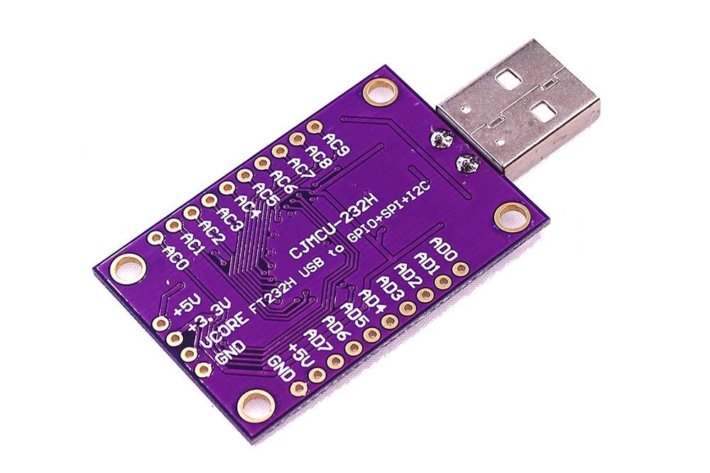
When you connect the debugger, Windows installs on it unsuitable drivers that must be changed using the Zadig program, everything is simple there, I will not describe it.
It connects to ESP32 devkit-v1 in the following way:
FT232H - ESP32
AD0 - GPIO13
AD1 - GPIO12
AD2 - GPIO15
AD3 - GPIO14
Then, in Project -> VisualGDB Project Properties
you need to make the following settings:
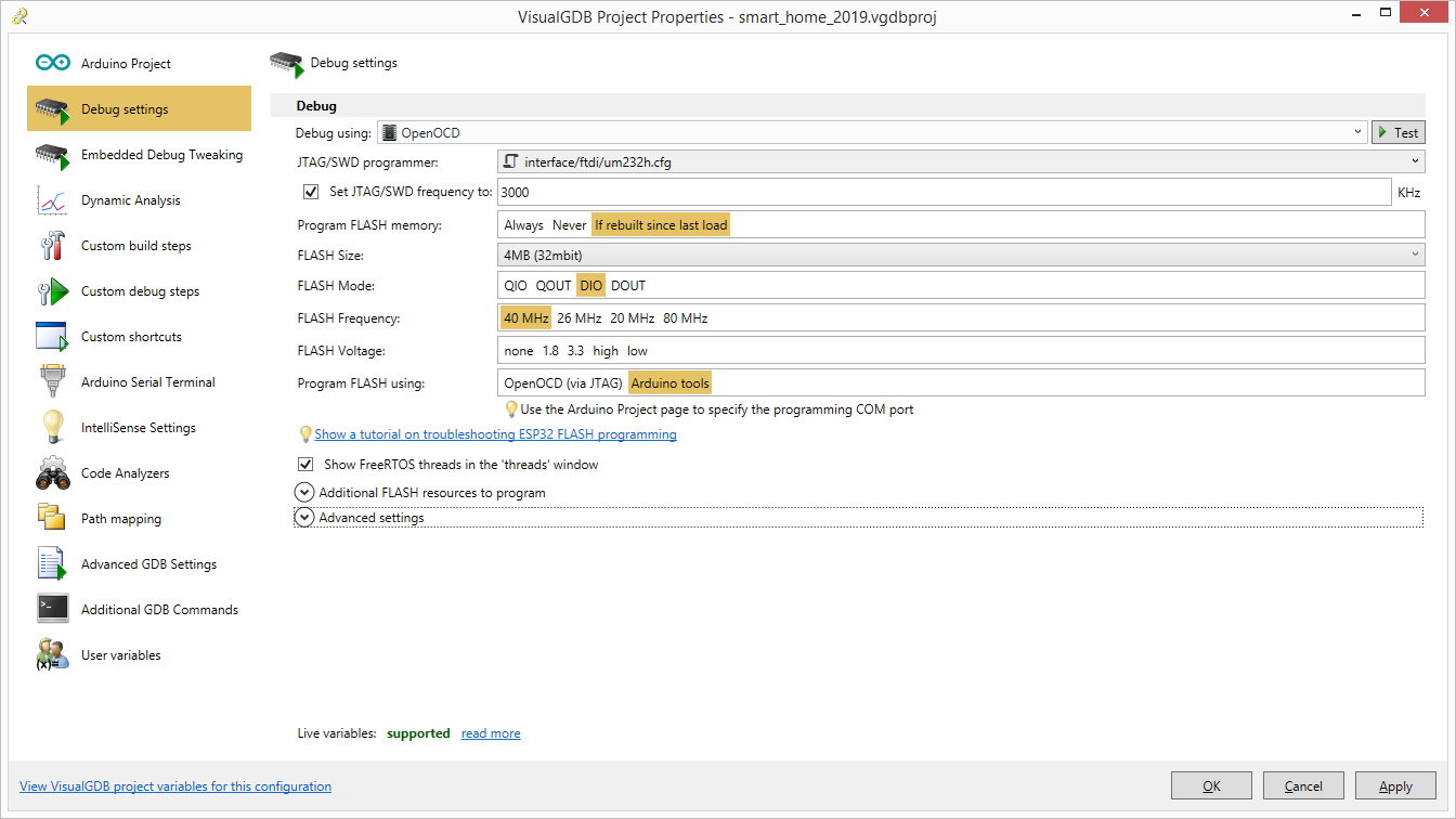
Then click on Test. Sometimes it happens that the connection is not established the first time, the process seems to freeze, then you need to interrupt and repeat Test. If everything is in order, the process of testing the connection takes about 5 seconds.
I usually built the project and uploaded it via USB to the ESP32 itself (not via the debugger), after which I started debugging using Debug -> Attach to Running Embedded Firmware
. In the code, you can set breakpoints, look at the values of variables at the time of break, and in the Debug -> Windows -> Threads
window you can see in which FreeRTOS task the code stopped, which is useful if an error occurs during debugging. These functions of the debugger were enough for me to work comfortably.
When I started working with NVS, debugging was constantly interrupted by obscure errors. As I understand it, this is because the debugger needs to create something like a dump in the default NVS section, but at this time the NVS is already used by the controller. Of course, this could be circumvented by creating 2 NVS partitions, one with the default name for debugging, and the other for its own needs. But there was nothing complicated there, in the added code, it worked the first time, so I did not check it.
Glitches ESP32
Like any device with Aliexpress, my ESP32 board had its own, nowhere described glitch. When she arrived, I fed some peripherals that worked on I2C from the board, but after some time, the board began to reboot if any consuming equipment or even just a capacitor was attached to the + 5V leg. Why so is completely incomprehensible.
Now I am powering the board from the Chinese charge 0.7A, the ds18b20 sensors from the foot of the 3.3V board, and the relay and motion sensor from another charge of 2A. The GND foot of the board is of course connected to the GND pins of the rest of the iron. Cheap and cheerful is our option.
About the project results
I got the opportunity to flexibly control the heating in the house, saving money and sweat earned. At the moment, if the heating maintains all day 23 degrees at -5 - -7 outside, it is somewhere around 11 hours of boiler operation. If during the day to maintain 20 degrees and warm to 23 only in the evening, then this is already 9 hours of operation of the boiler. The boiler capacity is 6 kW, with a current price of kilowatts of 2.2 rubles, this is about 26.4 rubles per day. The duration of the heating season in our area is 200 days, the average temperature in the heating season is just about -5 degrees. Thus, we get about 5000r savings for the heating season.
The cost of the equipment does not exceed 2000r, that is, the costs will be repelled in a few months, not to mention the fact that a finished system of such automation would cost at least 20,000r. Another thing is that I spent about a week of pure working time writing firmware and debugging, but in the course of work, for example, I finally realized what pointers are in C ++ and got a lot of other experience (for example, the experience of many hours of debugging incomprehensible glitches). And experience, as you know, is difficult to overestimate.
Screenshots of the Blynk mobile application:
Of course, the code in the project is not a masterpiece, but I wrote it in the conditions of a lack of time and focused mainly on readability. There is simply no time to refactor. In general, I have many excuses why my code is so scary, but this is my favorite, so I’ll dwell on it, I won’t develop the topic further.
If my scribble helps someone, I will be sincerely glad. I will be glad to any comments and suggestions.
List of used literature: