There was a matter, they asked me to expand on this topic in more detail right here, on Habr. Here quite a lot of review articles on railway topics are published, however, this topic has not yet been covered in detail. I think that it would be rather interesting to write an article about this, and possibly not one. Therefore, I ask those who are interested in how the brake systems of the railway transport are arranged, and for what reasons they are arranged that way.
1. The history of the appearance of an air brake
The task of controlling any vehicle includes controlling its speed. Rail transport is no exception, moreover, its design features introduce significant nuances into this process. The train consists of a large number of interlocked crews, and the resulting system has a considerable length and mass at a very decent speed.
By definition, brakes are a set of devices designed to create artificial, adjustable resistance forces used to control a reduction in vehicle speed.
The most obvious way to create braking force lying on the surface is to use friction. From the very beginning until today, a block friction brake has been used. Special devices - brake pads made of a material with a high coefficient of friction are mechanically pressed to the surface of the wheel (or to special disks mounted on the axis of the wheelset). Between the blocks and the wheel there is a friction force that creates a braking torque.
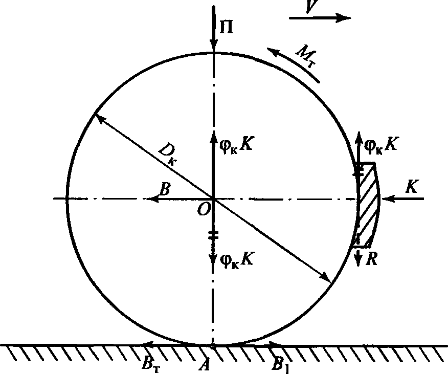
Regulation of the braking force is carried out by changing the force of pressing the pads to the wheel - brake pressing . The only question is which drive is used to press the pads, and the history of brakes, in part, is the history of the development of this drive.
The first railway brakes were mechanical and operated manually, separately on each carriage by special people - brakers or conductors. The conductors were located on the so-called brake pads that each car was equipped with and activated the brakes at the signal of the locomotive driver. The exchange of signals between the driver and conductors was carried out using a special signal rope stretched along the entire train, which activated a special whistle.
Antique biaxial freight car with brake pad. Visible handbrake
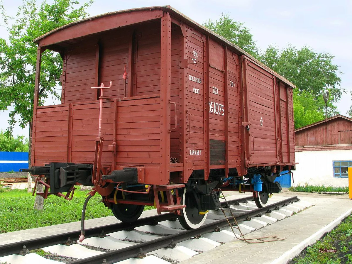
The mechanical brake itself has low power. The amount of braking depended on the strength and dexterity of the conductor. In addition, the human factor interfered in the operation of such a braking system - conductors did not always correctly fulfill their duties. It was not necessary to talk about the high efficiency of such brakes, as well as about increasing the speed of trains equipped with them.
Further development of the brakes required, firstly, an increase in braking pressure, and secondly, the ability to remotely control it on all cars from the driver’s workplace.
The hydraulic drive used in automobile brakes is widespread due to the fact that it provides high pressing with compact actuators. However, when using such a system in a train, its main drawback will appear: the need for a special working fluid - brake fluid, the leakage of which is unacceptable. The large length of the hydraulic brake lines in the train, together with the high requirements for their tightness, make it impossible and irrational to create a hydraulic railway brake.
Another thing is a pneumatic drive. The use of high-pressure air allows to obtain high braking pressures with acceptable dimensions of actuators - brake cylinders. There is no shortage of a working fluid — the air is around us, and even if a leakage of the working fluid from the brake system occurs (and it certainly arises), it can be relatively easily replaced.
The simplest brake system using compressed air energy is a direct-acting non-automatic brake
Scheme of direct-acting non-automatic brakes: 1 - compressor; 2 - the main reservoir; 3 - nutrient line; 4 - train crane operator; 5 - brake line; 6 - brake cylinder; 7 - a release spring; 8, 9 - mechanical brake gear; 10 - a brake shoe.
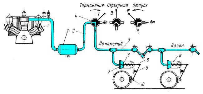
For the operation of such a brake, a stock of compressed air is required, stored on the locomotive in a special reservoir called the main reservoir (2). The injection of air into the main tank and maintaining a constant pressure in it is performed by a compressor (1), driven by the locomotive's power plant. The supply of compressed air to the brake control devices is carried out through a special pipeline called the feed (PM) or pressure line (3).
The brakes of the cars are controlled and compressed air is supplied to them by means of a long pipeline running through the entire train and called the brake line (TM) (5). When compressed air is supplied through the TM, it fills the brake cylinders (TC) (6) connected directly to the TM. Compressed air presses on the piston, pressing the brake pads 10 to the wheels, both on the locomotive and on the cars. Inhibition occurs.
To stop braking, that is, brake release, it is necessary to release air from the brake line into the atmosphere, which will lead to the return of the brake mechanisms to their original position due to the force of the release springs installed in the shopping center.
For braking, it is necessary to connect the brake line (TM) with the nutrient (PM). For holidays - connect the brake line to the atmosphere. These functions are performed by a special device - the train crane of the driver (4) - when braking, it connects the PM and the TM, during vacation - it disconnects these pipelines, while releasing air from the TM into the atmosphere.
In such a system, there is a third, intermediate position of the driver’s crane - the shut-off is when the PM and TM are disconnected, but there is no air release from the TM into the atmosphere — the driver’s crane completely isolates it. The pressure accumulated in the TM and the TC is maintained and the time it is maintained at the set level is determined by the amount of air leaks through various leaks, as well as by the thermal stability of the brake pads, which are heated by friction against the wheel tires. Setting in the roof both during braking and during vacation allows you to adjust the braking force in steps. Such a brake provides both step braking and step vacation.
Despite the simplicity of such a brake system, it has a fatal flaw - when the train is disconnected, the brake line breaks, air leaves it and the train remains without brakes. It is for this reason that such a brake cannot be applied in railway transport; the price of its failure is too high. Even without a train breaking, in the presence of a major air leak, the effectiveness of the brake will be reduced.
Based on the foregoing, there is a requirement that the braking of a train is initiated not by an increase, but by a decrease in pressure in the TM. But how then to fill the brake cylinders? This gives the second requirement - on each mobile unit in the train, a stock of compressed air must be stored, which must be quickly replenished after each braking.
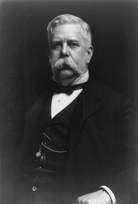
The engineering idea of the end of the 19th century came to similar conclusions, which was expressed in the creation by George Westinghouse in 1872 of the first automatic railway brake.
Westinghouse brake device: 1 - compressor; 2 - the main reservoir; 3 - nutrient line; 4 - train crane operator; 5 - brake line; 6 - air distributor (triple valve) of the Westinghouse system; 7 - brake cylinder; 8 - spare tank; 9 - stop crane.
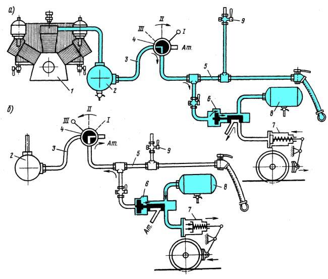
The figure shows the arrangement of this brake (Figure a - brake operation during vacation; b - brake operation during braking). The main element of the Westighouse brake was the brake air distributor or, as it is sometimes called, a triple valve . This air diffuser (6) has a sensitive body - a piston operating at a difference of two pressures - in the brake line (TM) and a spare tank (ZR). If the pressure in the becomes less than in the , then the piston moves to the left, opening the way for air from the to the shopping center. If the pressure in the becomes greater than the pressure in the - the piston moves to the right, communicating the TC with the atmosphere, and at the same time communicating and , ensuring the filling of the latter with compressed air from the .
Thus, if the pressure in the TM decreases, for any reason, whether it’s the driver’s actions, excessive air leakage from the TM or the train ruptures, the brakes will work. That is, such brakes have an automatic action . This property of the brake made it possible to add one more possibility for controlling the train brakes used on passenger trains to this day - an emergency stop of a train by a passenger by communicating the brake line with the atmosphere through a special valve - a stop valve (9).
It is, however, familiar with this feature of the train's brake system that it is ridiculous to watch films where thief-cowboys famously unhook a train with gold from the train. In order for this to be possible, cowboys must, before uncoupling, close the end valves on the brake line, disconnecting the brake line from the connecting arms between the cars. But they never do that. On the other hand, closed end cranes have repeatedly caused terrible disasters related to brake failure, both here (Kamensk in 1987, Eral-Simskaya in 2011) and abroad.
Due to the fact that the filling of the brake cylinders comes from a secondary source of compressed air (spare reservoir), without the possibility of its constant replenishment, such a brake is called non-acting . Charging of air defense with compressed air occurs only when the brake is released, which leads to the fact that during frequent braking and subsequent release, with insufficient time delay after holiday, the air defense will not have time to charge to the desired pressure. This can lead to complete depletion of the brake and loss of control of the train brakes.
The pneumatic brake has another drawback related to the fact that the pressure drop in the brake line, like any disturbance, spreads in the air with a high, but still finite speed - not more than 340 m / s. Why not more? Because the speed of sound is an ideal option. But in the train’s pneumatic system, there are a number of obstacles that reduce the propagation speed of the pressure-drop shock associated with resistance to air flow. Therefore, if you do not take special measures, the speed of pressure reduction in the TM will be the lower, the farther from the locomotive the wagon is located. In the case of the Westinghouse brake, the speed of the so-called brake wave does not exceed 180 - 200 m / s.
Nevertheless, the appearance of a pneumatic brake made it possible to increase both the power of the brakes and the speed of managing them directly from the driver’s workplace. This served as a powerful impetus to the development of railway transport, an increase in the speed and weight of trains, and as a result, a tremendous increase in freight traffic on the railway, the increase in the length of railway lines around the world.
George Westinghouse was not only an inventor, but also an enterprising businessman. He patented his invention in 1869, which allowed him to expand the mass production of brake equipment. Quite quickly, Westinghouse's brake became widespread in the United States, Western Europe, and the Russian Empire.
In Russia, the brake of Westinghouse reigned supreme before the October Revolution, and for quite some time after it. The Westinghouse company built its own brake plant in St. Petersburg, and also skillfully displaced competitors from the Russian market. However, Westinghouse's brake had a number of fundamental flaws.
Firstly, this brake provided only two operating modes: braking until the brake cylinders were completely full, and vacation - emptying the brake cylinders. It was impossible to create an intermediate value of the brake pressure with its long-term maintenance, that is, there was no overlap mode in the Westinghouse brake. This did not allow for precise control of the speed of the train.
Secondly, Westinghouse's brake did not work well on long trains, and if in passenger traffic it was somehow possible to put up with it, then there were problems in the freight. Remember the brake wave? So, the Westinghouse brake did not have the means to increase its speed, and in a long train the pressure drop in the TM on the last car could start too late, and at a rate much lower than in the head of the train, which created a wild uneven response of the brake devices in composition.
I must say that all the activities of Westinghouse, both in Russia at that time and around the world, are thoroughly saturated with the capitalist scent of patent wars and unfair competition. This provided such an imperfect system with such a long life, at least in that historical period.
At the same time, it must be recognized that the Westinghouse brake laid the foundations for braking science and the principle of its action has remained unchanged in modern brakes of rolling stock.
2. From the brake of Westinghouse to the brake of Matrosov - the formation of domestic brake science.
Almost immediately after the appearance of the Westinghouse brake and recognition of its shortcomings, attempts arose to improve this system, or to create another, fundamentally new one. Our country was no exception. At the beginning of the 20th century, Russia had a developed network of railways, which played a significant role in ensuring the economic development and defense capabilities of the country. The increase in the efficiency of transport is associated with an increase in its speed and mass of the transported cargo at one time, which means that the issues of improving brake systems are urgently raised.
A significant impetus to the development of inhibitory science in the RSFSR and later the USSR was the decrease in the influence of large Western capital, in particular the Westinghouse company, on the development of the domestic railway industry after October 1917.
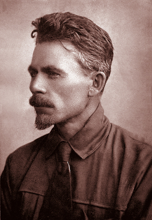
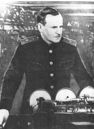
F.P. Kazantsev (left) and I.K. Sailors (right) - the creators of the domestic railway brake
The first sign, the first major achievement of the young domestic inhibitory science, was the development of engineer Florence Pimenovich Kazantsev. In 1921, Kazantsev proposed a direct-acting automatic brake system . The diagram below describes all the basic ideas introduced not only by Kazantsev, and its task is to explain the basic principles of the advanced automatic brake
Direct automatic brake: 1 - compressor; 2 - the main reservoir; 3 - nutrient line; 4 - train crane operator; 5 - power supply leaks brake lines; 6 - brake line; 7 - connecting brake hoses; 8 - end crane; 9 - stop crane; 10 - check valve; 11 - spare tank; 12 - air distributor; 13 - brake cylinder; 14 - brake linkage.
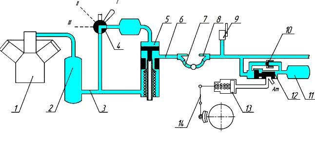
So, the first basic idea is that the pressure in the TM is controlled indirectly - through reducing / increasing the pressure in a special tank called a surge tank (SD). It is shown in the figure to the right of the driver’s crane (4) and on top of the TM leakage power device (5). The density of this tank is technically much easier to provide than the density of the brake line - a pipe reaching a kilometer length and running through the entire train. Relative pressure stability in the SD allows maintaining pressure in the TM, using the pressure in the SD as a reference. Indeed, the piston in the device (5) lowers when the pressure in the TM decreases, opening the valve filling the TM from the feed line, thereby maintaining the pressure in the TM equal to the pressure in the SD. This idea still had a long way to go, but now the pressure in the HM did not depend on the presence of external leaks from it (to known limits). Device 5 migrated to the driver’s crane and remains in it, in a modified form, to this day.
Another important idea that underlies the design of this type of brake is the supply of air conditioners from TM through a non-return valve 10. When the pressure in the TM exceeds the pressure in the air conditioner, this valve opens, filling the air conditioner from the TM. Thus, there is a continuous replenishment of leaks from the spare tank and the inexhaustibility of the brake is ensured.
The third important idea proposed by Kazantsev is the design of the air distributor, which operates on a difference of not two pressures, but three - pressure in the brake line, pressure in the brake cylinder, and pressure in a special working chamber (RK), which, when released, is powered by pressure from the brake line , together with a spare tank. In braking mode, the RK is disconnected from the spare reservoir and the brake line, while maintaining the value of the initial charging pressure. This property is widely used in the brakes of rolling stock both to provide step-by-step tempering and to control the uniformity of filling of the shopping center along the train in freight trains, because the working chamber serves as the standard for the initial charging pressure. Based on its value, it is possible to provide stepwise vacation and organize earlier filling of the shopping center in the tail cars. I will leave a detailed description of these things for other articles on this topic, for now I will only say that the work of Kazantsev served as an incentive for the development of a scientific school in our country, which led to the development of original rolling brake systems.
Another Soviet inventor who dramatically influenced the development of domestic rolling stock brakes was Ivan Konstantinovich Matrosov. His ideas did not fundamentally differ from the ideas of Kazantsev, but the subsequent operational tests of the brake systems of Kazantsev and Matrosov (together with other brake systems) showed the significant superiority of the second system in terms of performance when applied primarily to freight trains. Thus, the Matrosov brake with the air distributor conv. No. 320 became the basis for the further development and design of braking equipment for railways of 1520 mm gauge. The modern automatic brake used in Russia and the CIS countries can rightfully be named after Matrosov’s brake, as it absorbed, at the initial stage of its development, the ideas and design decisions of Ivan Konstantinovich.
Instead of a conclusion
And what is the conclusion? Work on this article convinced me that the topic was worthy of a series of articles. In this pilot article, we touched on the history of the development of rolling stock brakes. In the following, we will go into piquant details, affecting not only the domestic brake, but also the development of colleagues from Western Europe, highlighting the device of brakes of various types and types of rolling stock services. So, I hope, the topic will be interesting, and until we meet again on the hub
Thank you for your attention!