A step-by-step guide on moving from an invented idea to a working product.
Waiting Against Reality

Have you ever asked yourself the following questions?
- Can hot glue fix EVERYTHING?
- Is smart equipment hard to make?
- Can you pour concrete into a cardboard form?
If not, maybe it's time. But if you did, then welcome to the club! We recently had an internal hackathon at EL Passion , and I had a difficult idea. Making a lamp!
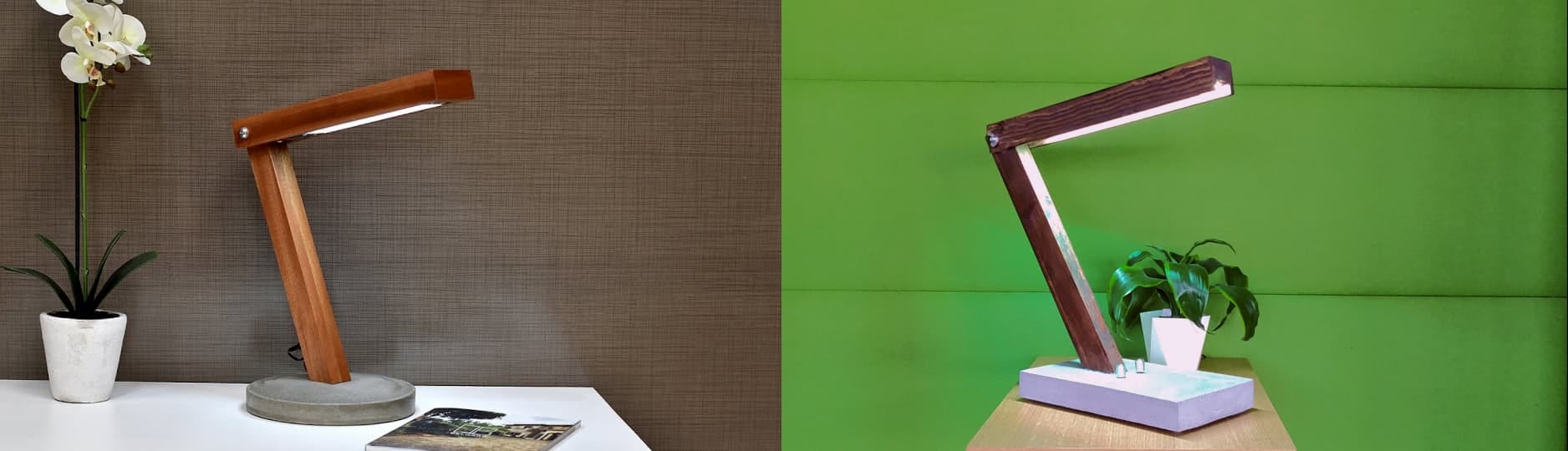
Smart lamp.
Smart lamp made of concrete.
Smart wood / concrete lamp with RGB LED strip ...
AND BLUETOOTH!
In two short days of the hackathon (with a little overhead) we did it all!
It all started with electronics
About two months ago, I started playing with electronics. I wanted to broaden my horizons, find out which cables to cut in case of an uprising of intelligent machines, and go beyond my knowledge of Frontend Engineering. I think most of you may be similar.
I started with the basics, got some components, looked at the tutorials, and then I could not decide what to do next.
After about two months, I remembered that a hackathon was being prepared!
I also recently saw Stephanie Nemeth speak at a conference where she showed fantastic things you can do with Arduino and RGB backlighting. So I decided that I want to do something as neat as this.
But I wanted to do something that would be useful, functional, and would require skills in DIY, programming, and electronics.
I settled on the most obvious thing that can be done with the help of lamps - lamps. And I found the perfect DIY assembly that I wanted to emulate.
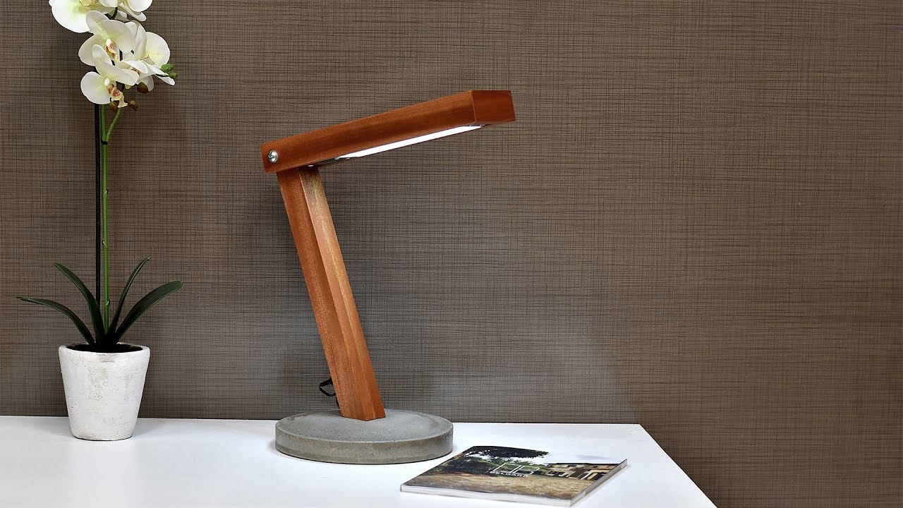
DIY lamp from a DIY Creators youtube tutorial
I already had an idea. Now I need a team.
Pitching - Team Building
Three days before the hackathon, we usually have a presentation where we present our ideas to the rest of the company and gather people who will work on our project. I'm not a big seller, so mine sounded something like this:
Hmmm, so yes, I want to make a concrete smart lamp. Many thanks.
Despite the lack of information, my team had five people interested in joining! We had an impressive set of skills:
- Maciej - I was as the group’s CEO. I planned the assembly, made sure that we had everything we needed and helped put all the parts together (figuratively and figuratively).
- Wojtek - he took over the post of head of the electronics department. He planned the circuit, created a prototype, and worked with Yakub (iOS) to make sure that Bluetooth works. He also made sure that we did not burn the building.
- Ula - Concrete head of the carpentry workshop and hot glue. She made sure that we did everything right, kept the deadlines and worked on the wooden lamp housing.
- Yeah - Team Handyman. It appeared when we needed it the most, and made sure that our “manual” part of the assembly would work.
- Yakub is the head of the mobile development department. Make sure that we have an amazing, native, cross-platform, but in fact the only ios application, because who uses android to control the lamp.
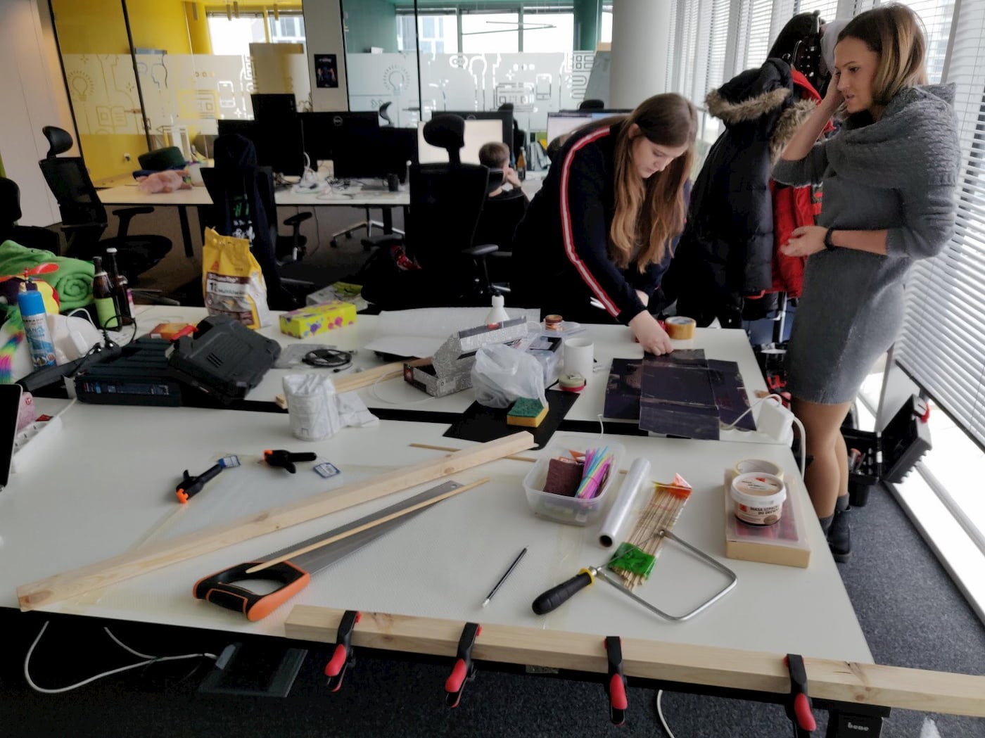
Shopping
Let's look at the shopping list . I listed only what we used and constantly built into the lamp. All additional equipment, Arduino (prototyping, loading code into AVR) and the components that we hacked are not taken into account.
Total cost: 159 zlotys (about 43 US dollars).
You can get all the items at a lower price, but in our case it was quite urgent.
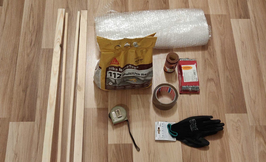
Boards, concrete, sanding paper and other useful things.
Part 1: Concrete foundation
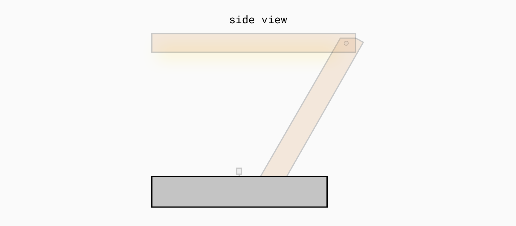
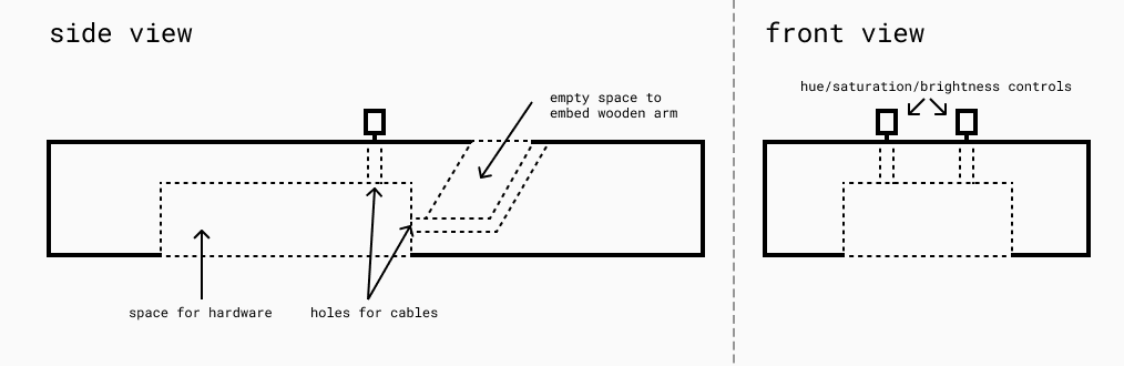
The construction phase of the project was an exciting test. The first two hours we spent discussing how to make a foundation for concrete that would meet the following requirements:
- Leave a place at the bottom for electronics
- Leave two holes for the hue and saturation knobs
- Leave room for a wooden hand
We came up with something like this:
It looks simple, but it was not so easy to do. To create the base, we used a cardboard box, a lot of gray ribbon, a box of “magic mouse 2”, two plastic straws and some hot glue.
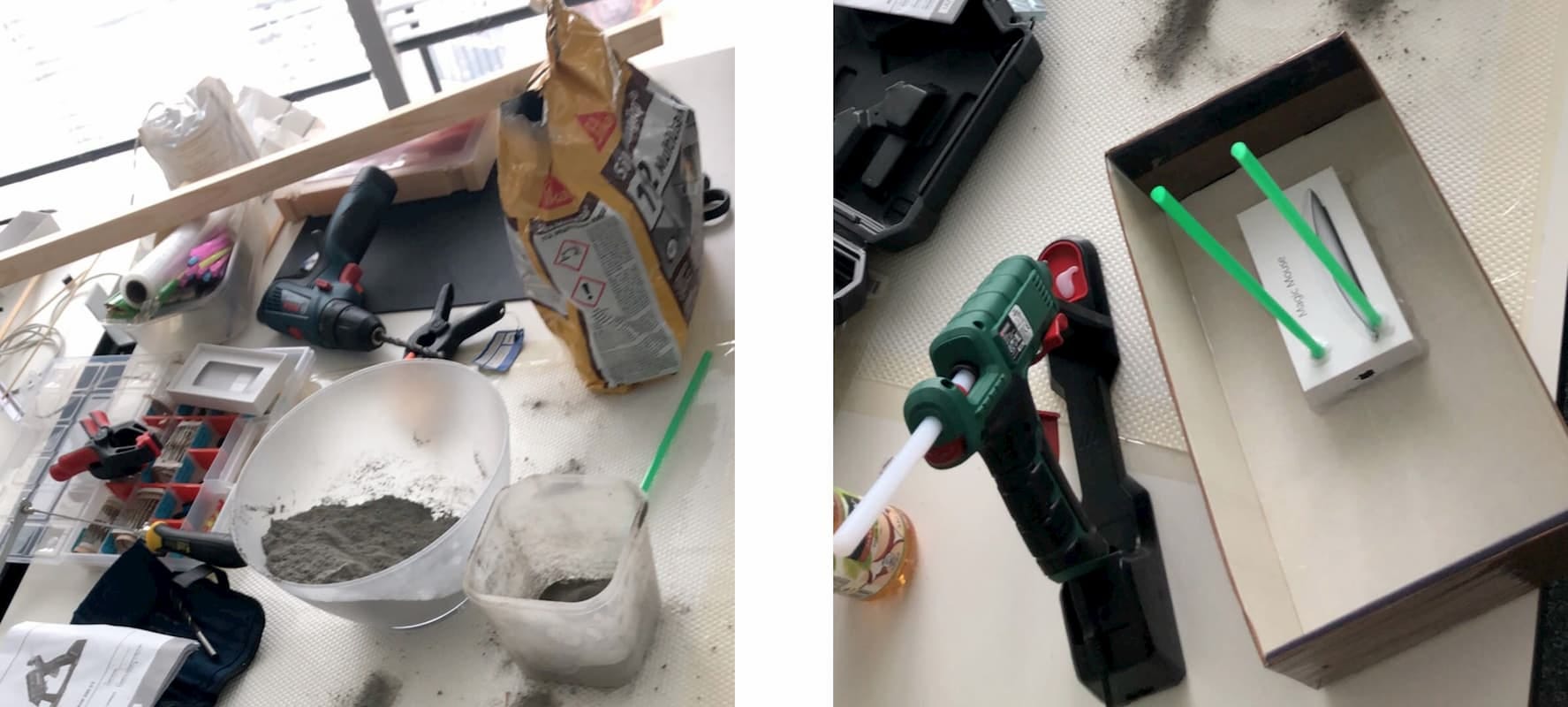
Later we mixed and added concrete.
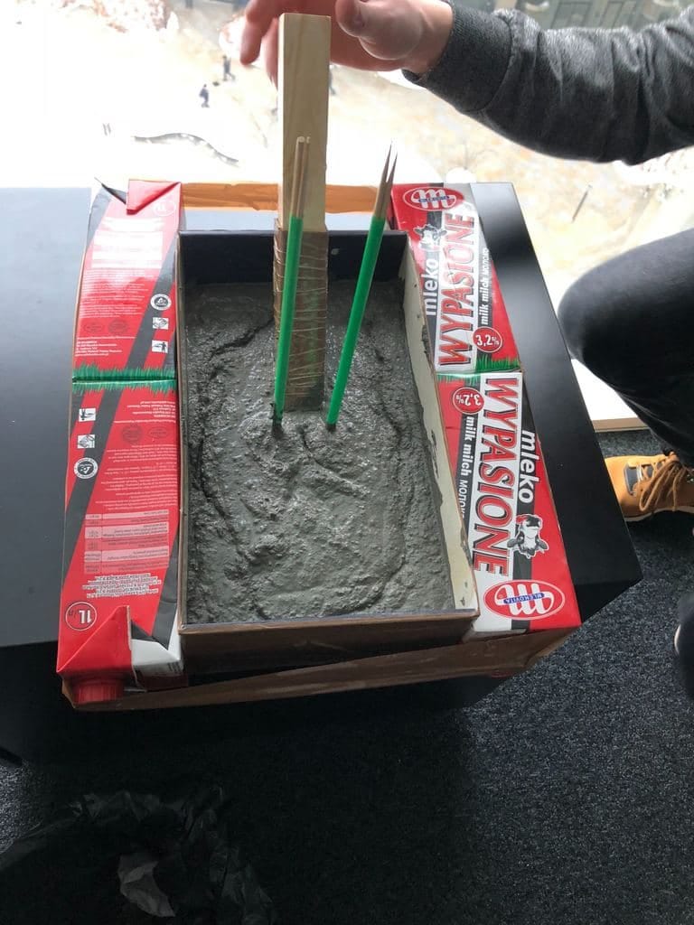
Not for people with lactose intolerance, sorry.
We did not want the dressing to deform, so we used more tape and four liters of milk. We also laid the wooden base in concrete so that we had a place for it later (although we almost forgot about it). All this is equivalent to a “quick fix” in production systems, but as they say:
If it looks stupid but works, it's not stupidThis quote has become our motto for the rest of the assembly.
Smart people
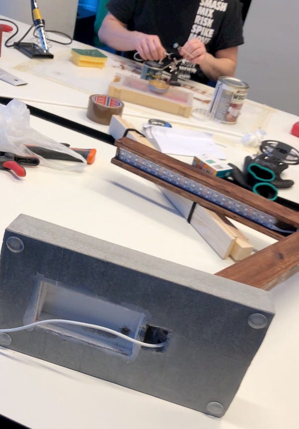
I don’t have an image of the base immediately after removing it from the cast, but here it is after a little grinding and already with the wooden lever installed. We also added silicone feet to prevent the concrete from scratching the countertop.
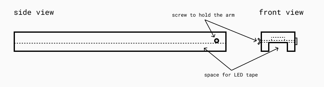
Part 2: Wooden Hand
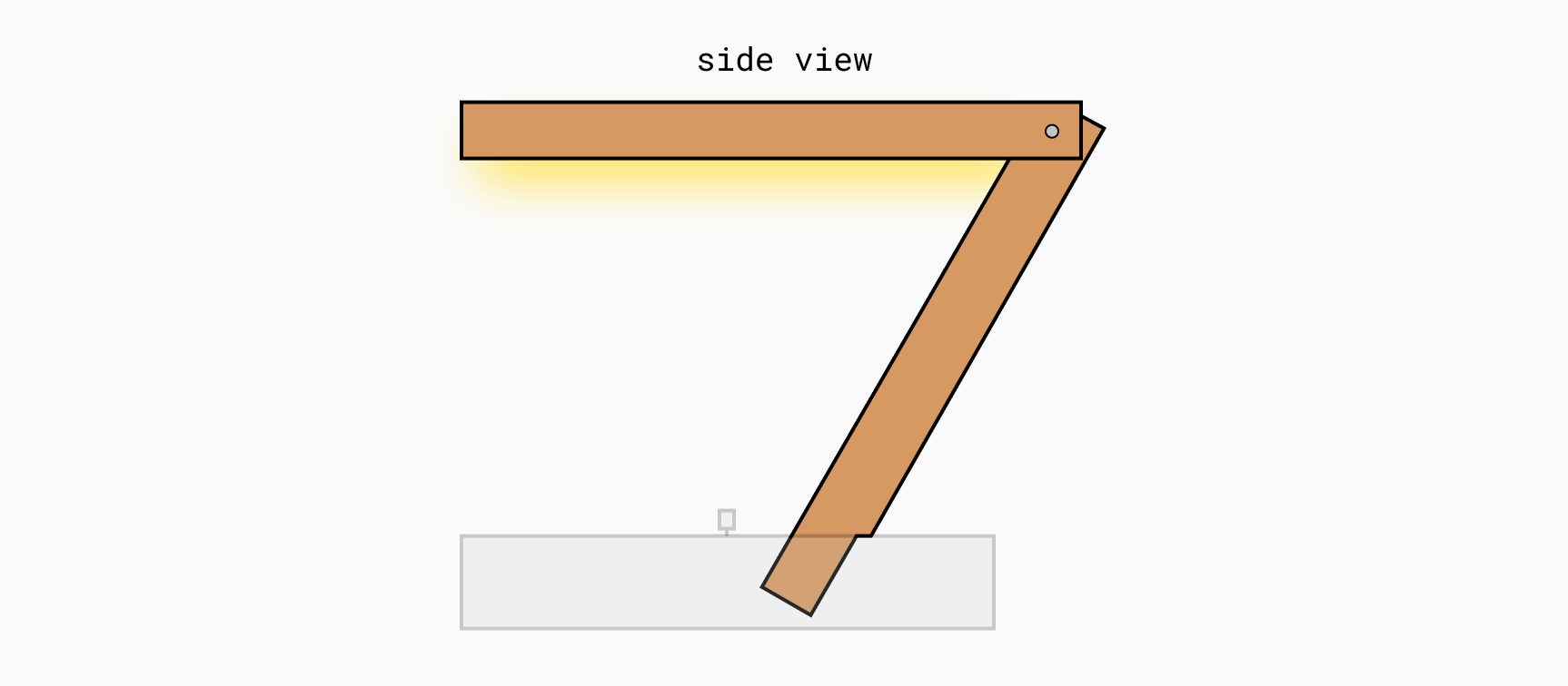
The bracket consists of two separate parts: the top of the lamp and the base with a cable inside. We connected them with a large screw, for which we drilled holes in both the upper and lower parts.
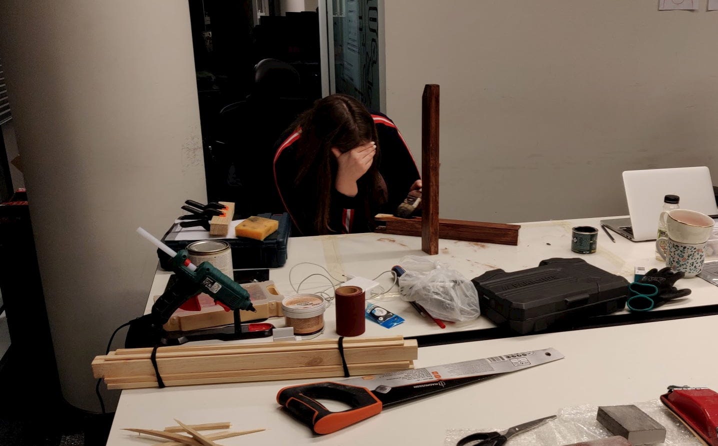
Miraculously, we did not burn the office.
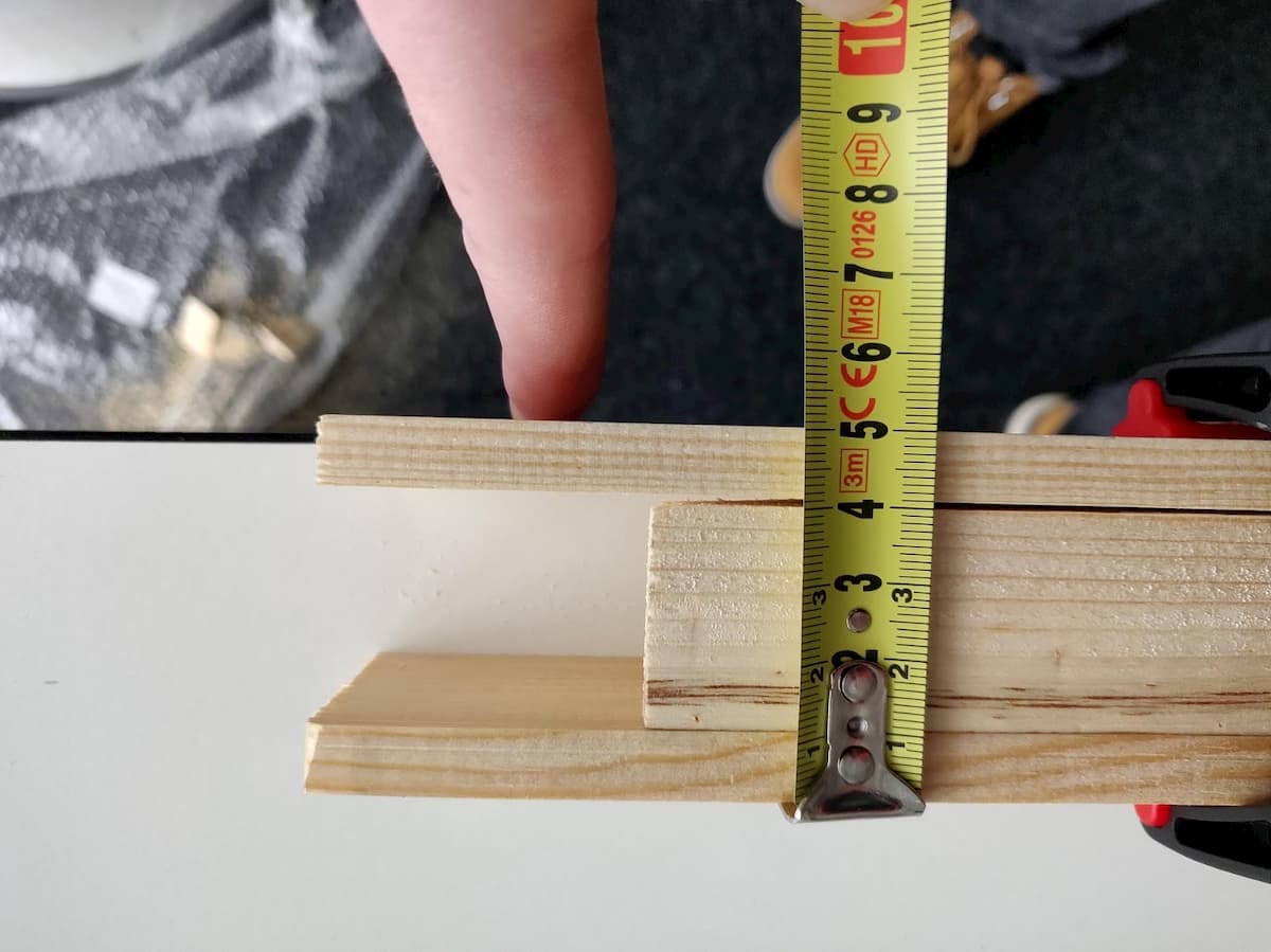
It turns out that measuring things right is difficult.
We started by making the upper arm.
Full view.
The upper part was rather complicated because it required delicate work with a soldering iron, but let's start with the basics. We made it from three pieces of wood, two thin (side) and square. First, we glued everything together, drilled a hole for the large screw that holds the upper and lower parts together. After some grinding, to compensate for the fact that the boards were slightly curved, Ula painted her hand, and when it dried, I continued and began to install LED strips on it.
The first thing I did was determine how to cut the LED strip. We did not want to put one long part inside, since it would not give so much light, therefore, measuring how much we fit, I cut into three strips, each of which had a size of 35 cm. Then I soldered the main cable with the first part LED strip and used a heat shrink tube to secure the connection.
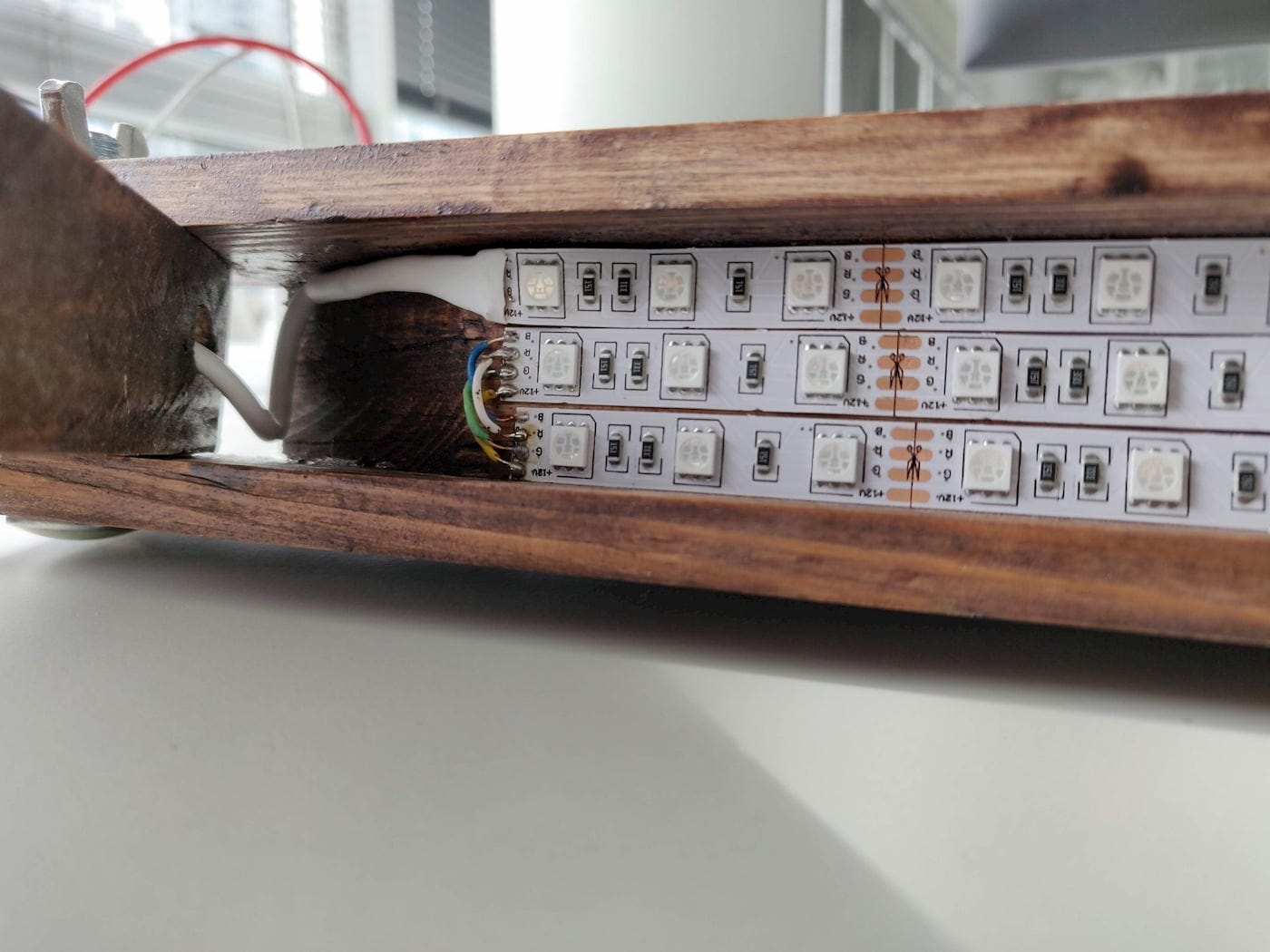
Heat shrink tubes and solder joints connect two LED strips.
After gluing the first strip to the tree, I realized that I had forgotten which cables I connected to the outputs of Red, Green, Blue and 12V +. It was a small setback, but fortunately we had a multimeter that allowed us to check the connections.
The next thing I needed to do was solder the two LED strips in series with the first part. It took me some time, but I managed to do it, despite the $ 8 soldering iron with a tip, which decreased with each use. We tested this by connecting the cable to the breadboard and using one of the rotary encoders to change the color.
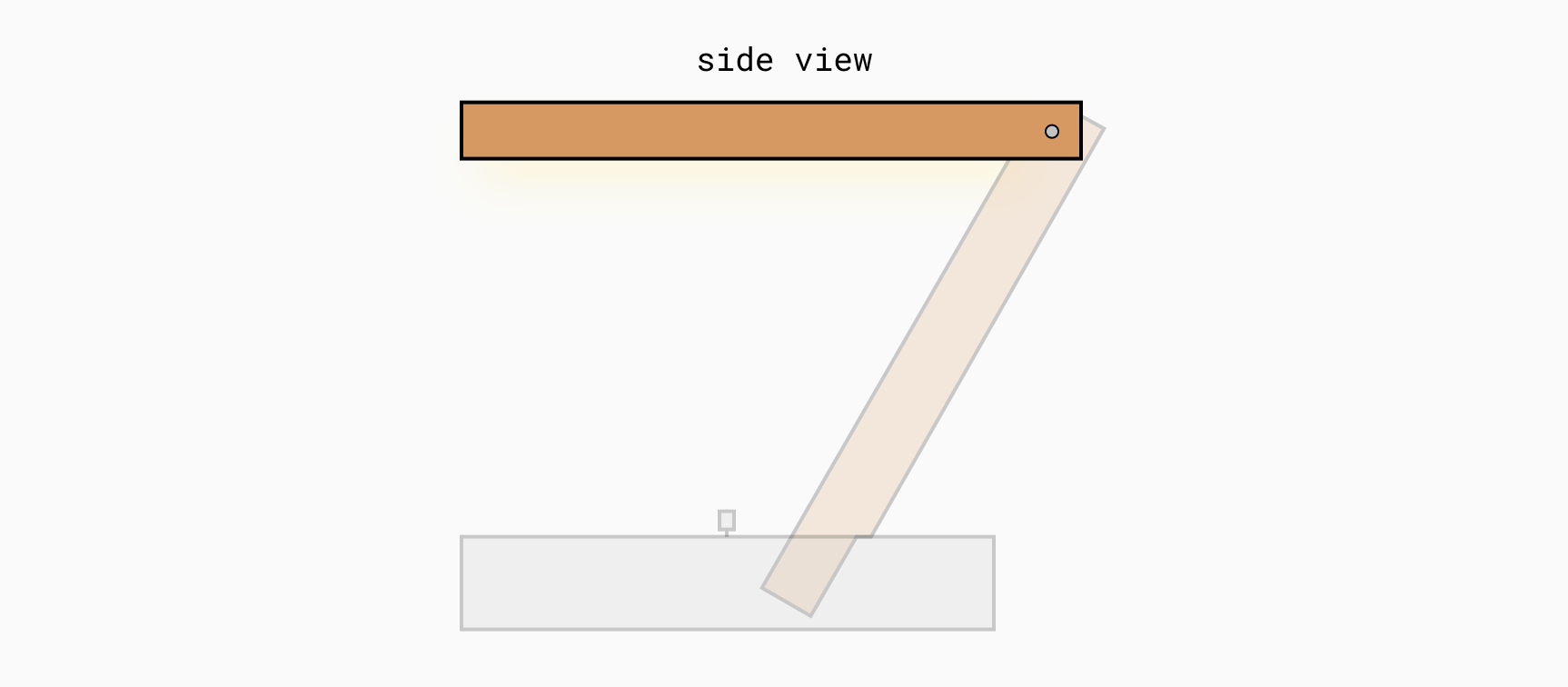
The lower arm, as shown in the figure above, was also quite complex
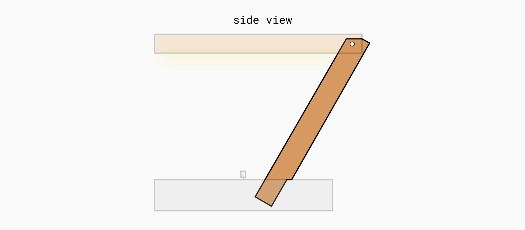
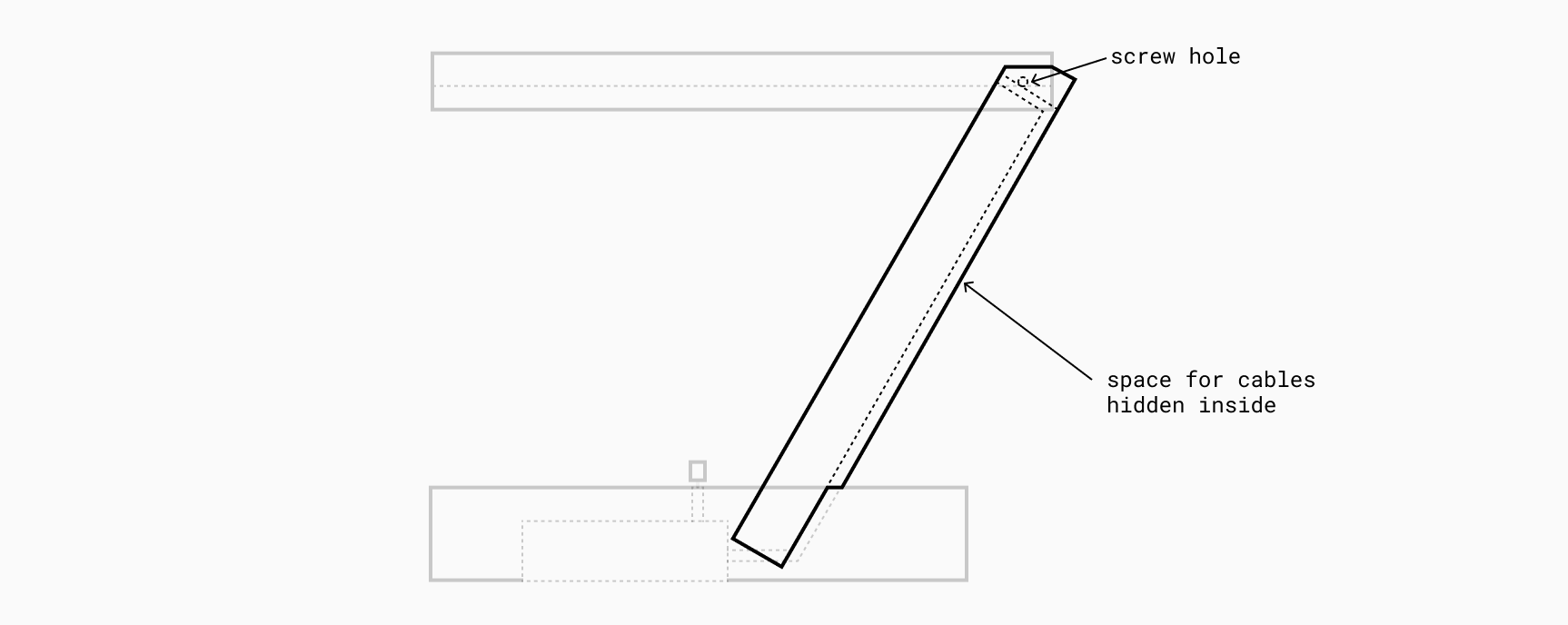
The lower part of the arm was complicated because we had to insert the cable inside it. We thought about cutting it in half, allocating a little space, and then folding it together, but this will be error prone and time consuming. In the end, we decided to glue three additional pieces of wood to make room for the cable, as shown in the graph. This is also the reason why the part inside the base is a bit narrower.
We lacked a few parts, pieces of wood and a screw that would hold our hand together. We took a short break from work and went to the store to buy all these things.
The natural pine color was not so good, so Ula painted the upper and lower parts of the lamp so that they became a little darker. We left it to dry for the night, and the next day we plugged it in, and it looked great!
The painting process.
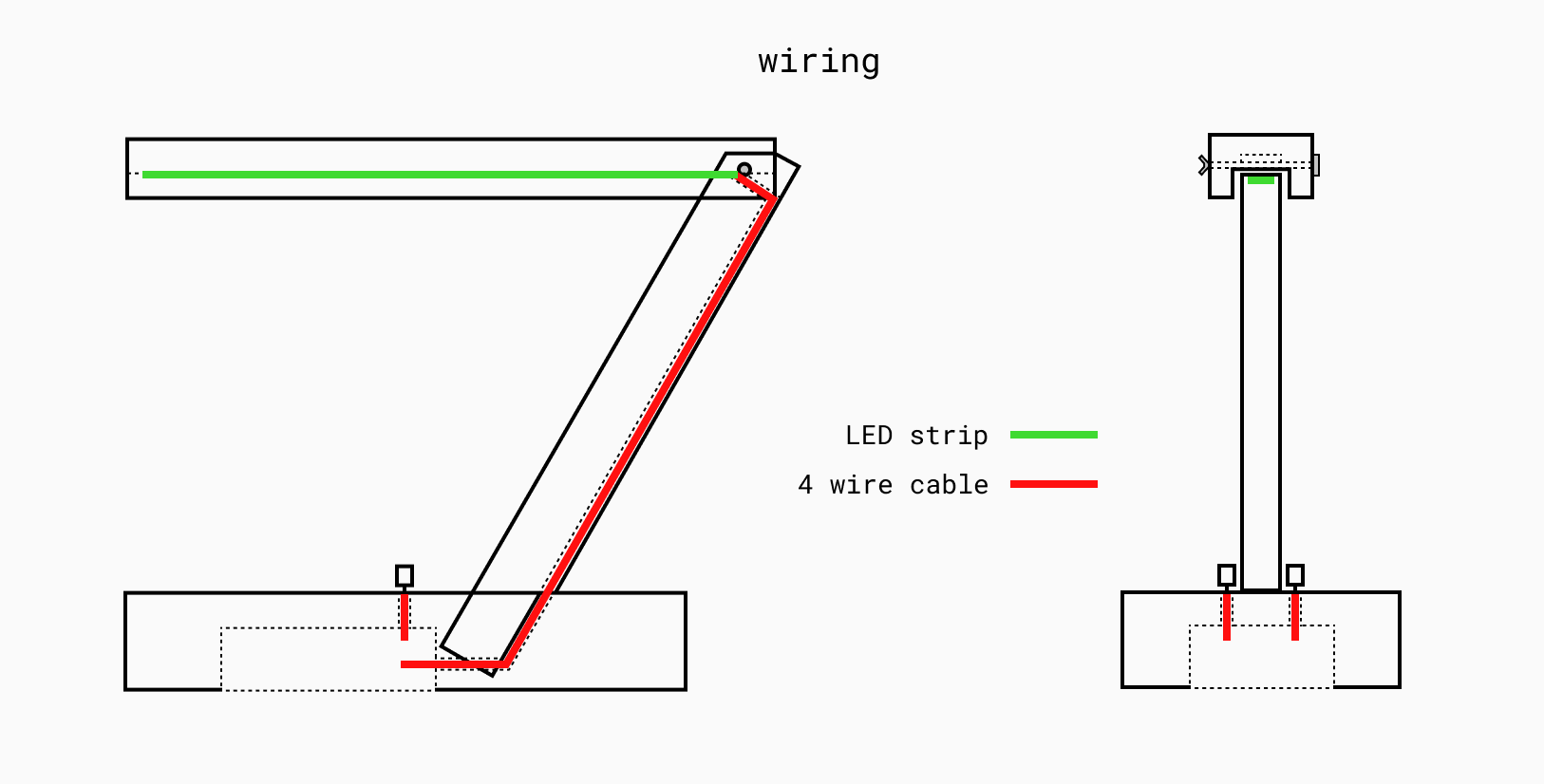
The location of the cables inside the lamp.
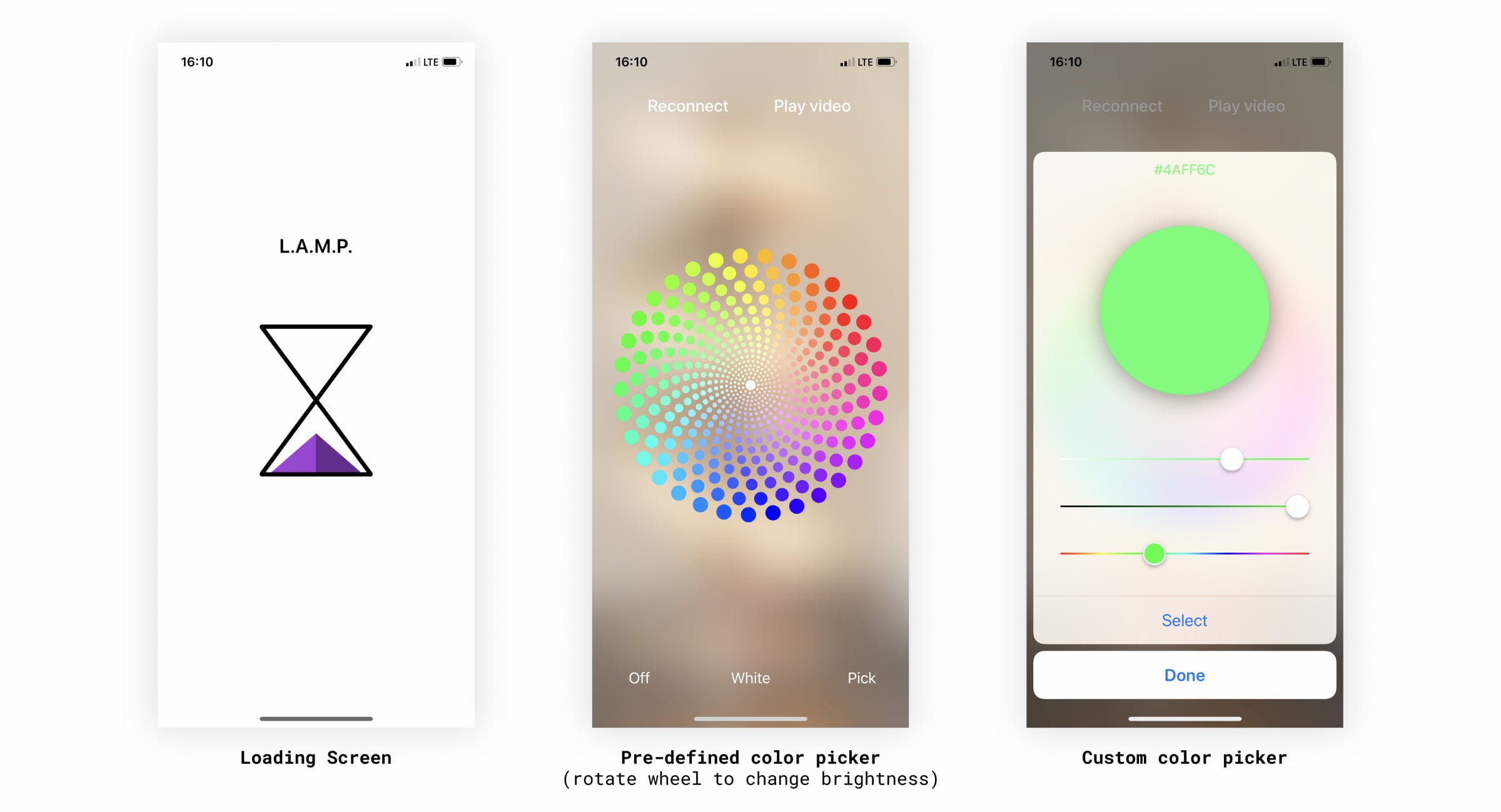
Part 3: iOS app software
I was not involved in the process of creating an iOS application, so I can’t give a deeper understanding of the code. Yakub took the lead and delivered the working application until the end of the first day. On the second day, he expanded it by adding more incredible features, such as Ambilight support, when the lamp synchronizes colors with it during video playback (demo at the end of the article).
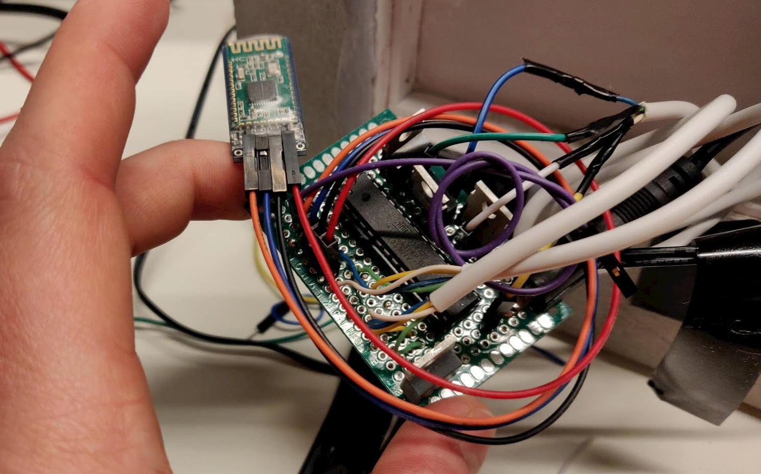
There were some problems with the Bluetooth connection, more precisely, one Bluetooth module was connected to iOS, but not to Android, and the other went the other way around. Now the lamp works only with iOS, but for MVP this is enough. And the Bluetooth module can be easily switched if necessary, as it is not soldered in place.
IOS app code
Based on my experience, I can say that the application looks impressive, and the speed with which Yakub provided it is also incredible!
Arduino / ATmega Code
All open source code on GitHub . You can get through this. I am not going to go into the deep technical details of how this works. Wojtek, who wrote most of the code, would be better for this, so I created a general overview of how everything works. A simplified algorithm is as follows:
Simplified lamp software algorithm
Moving from Arduino to ATmega
Wojtek wrote the first version of the code for Arduino, and later I updated it to work on a regular ATmega chip. The differences are minimal since I introduced only two major changes:
I deleted one of the serial connections - previously we had one serial connection, which we used for debugging (printing to the console on the computer), and the other for Bluetooth. When we switched to ATmega, we no longer needed a debugger that freed up two pins and simplified the connections.
I changed the location of the pins - to better place everything on the layout, I changed the physical location, which required a change in the reference pins in the code.
If you are interested, you can see a request for receipt, which contains the differences of all changes.
Part 4: Electronics
Our plan was quite ambitious for such a short time, but, fortunately, Wojtek was pretty smart and used to play with electronics, so he was the “leader” in this part.

We started with children's steps, testing various solutions by trial and error. Wojtek worked on the code and the circuit at the same time and checked how everything works. The electronic part of the lamp consisted of:
- Microcontroller - Brain
- Two knobs with buttons for controlling brightness, hue and saturation
- Bluetooth module for wireless control
- LED strip for light
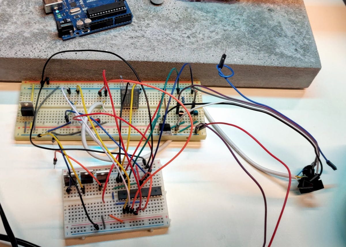
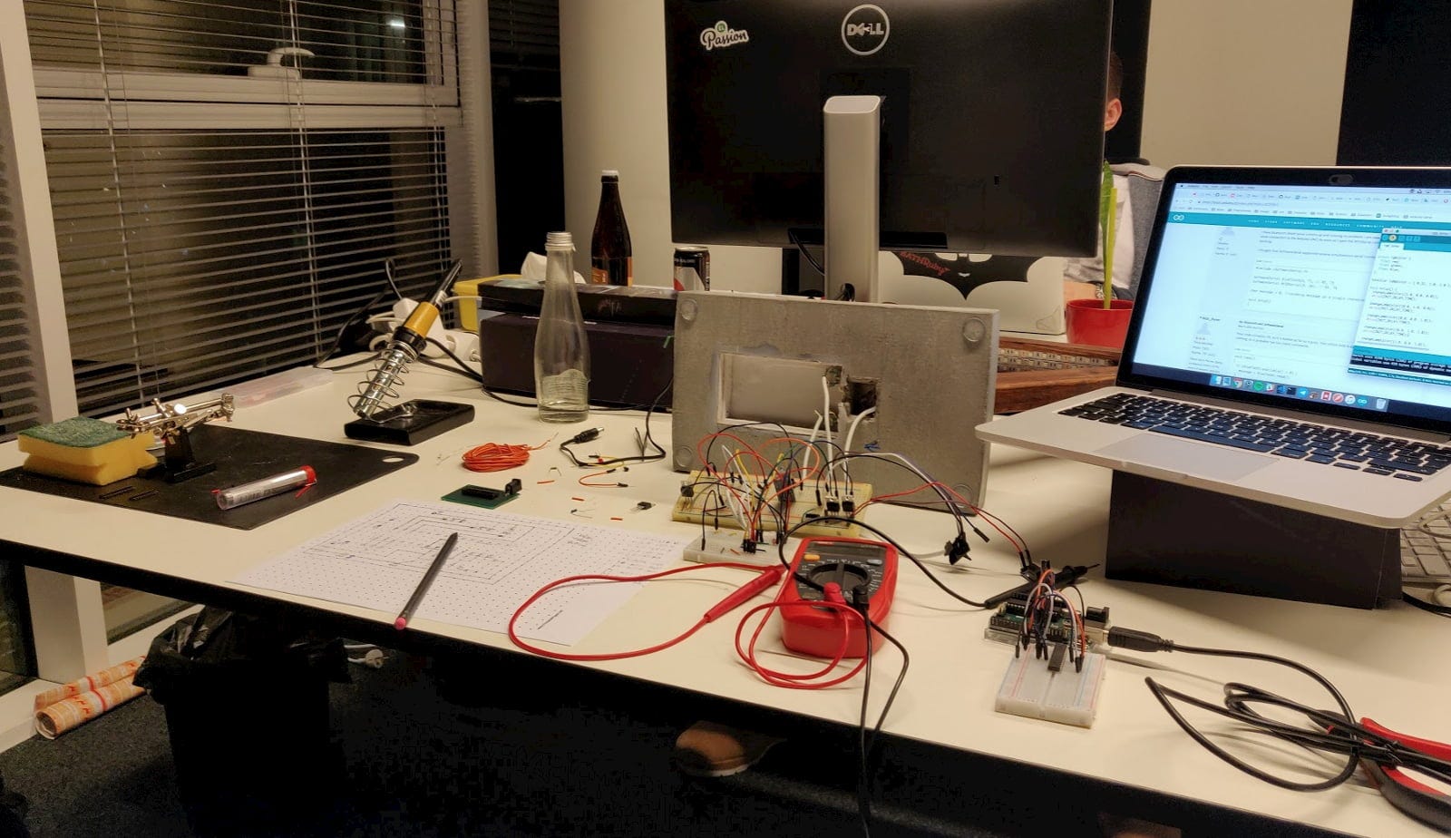
First, we used an Arduino instead of a stand-alone microcontroller, and placed everything on the layout to simplify the development process. At the end of the second day, we had everything related to the prototype board. Bluetooth, rotary encoders and Arduino. Here's how it looked at the demo session:
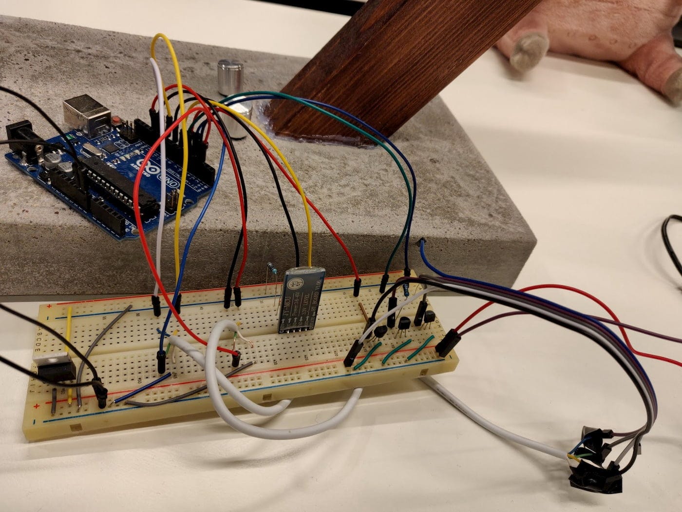
We also managed to burn one Bluetooth chip ...
Part 5: Let's make it smaller!
After the hackathon, I wanted to spend some time and squeeze the electronics so that it fits inside the lamp so that the assembly is complete. To compress the electronics, I had to:
- Replace Arduino with ATmega328
- Plan connections on cardboard
- Solder the AVR socket so that we can replace it if necessary
- Solder non-removable elements (transistors, DC socket, etc.)
- Put it all together
I started by replacing the Arduino. To do this, I needed to install the bootloader on the AVme ATmega (it is the same as in Arduino). I looked at several tutorials on how to install a bootloader and how to use Arduino as an ISP programmer (it allows you to download software to a microcontroller without any additional hardware). After that, I updated the code to use slightly different contacts and voila!
Arduino disconnected successfully!
Then I had to solder it all on a tiny cardboard.
This was the first time I worked with ribbon cards, and I could not find any simple software that would help with the design of physical circuits, so I went to an old school and planned it manually. I printed a sheet of paper with a dotted grid, where the dots were holes in the cardboard. Then I drew all the connections and how they should fit based on the current layout scheme.
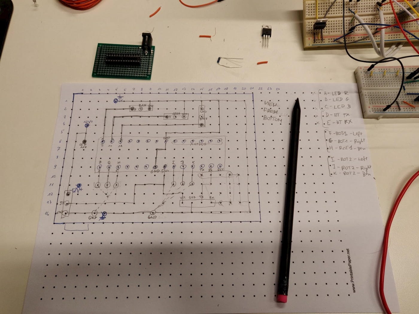
Planning the circuit of the circuit itself took me more than an hour.
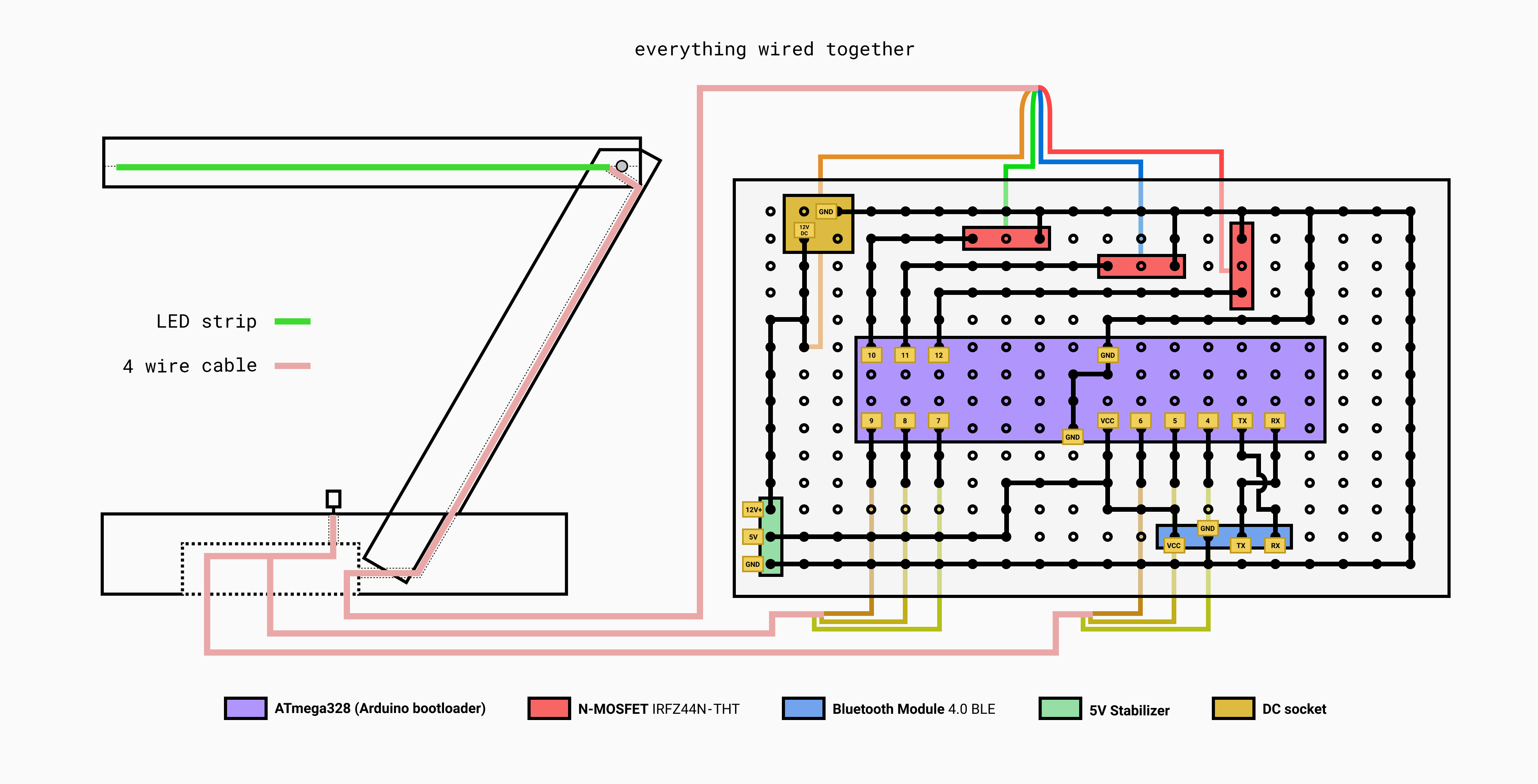
To make it more understandable and visible, I created a graphic that represents a diagram on cardboard.
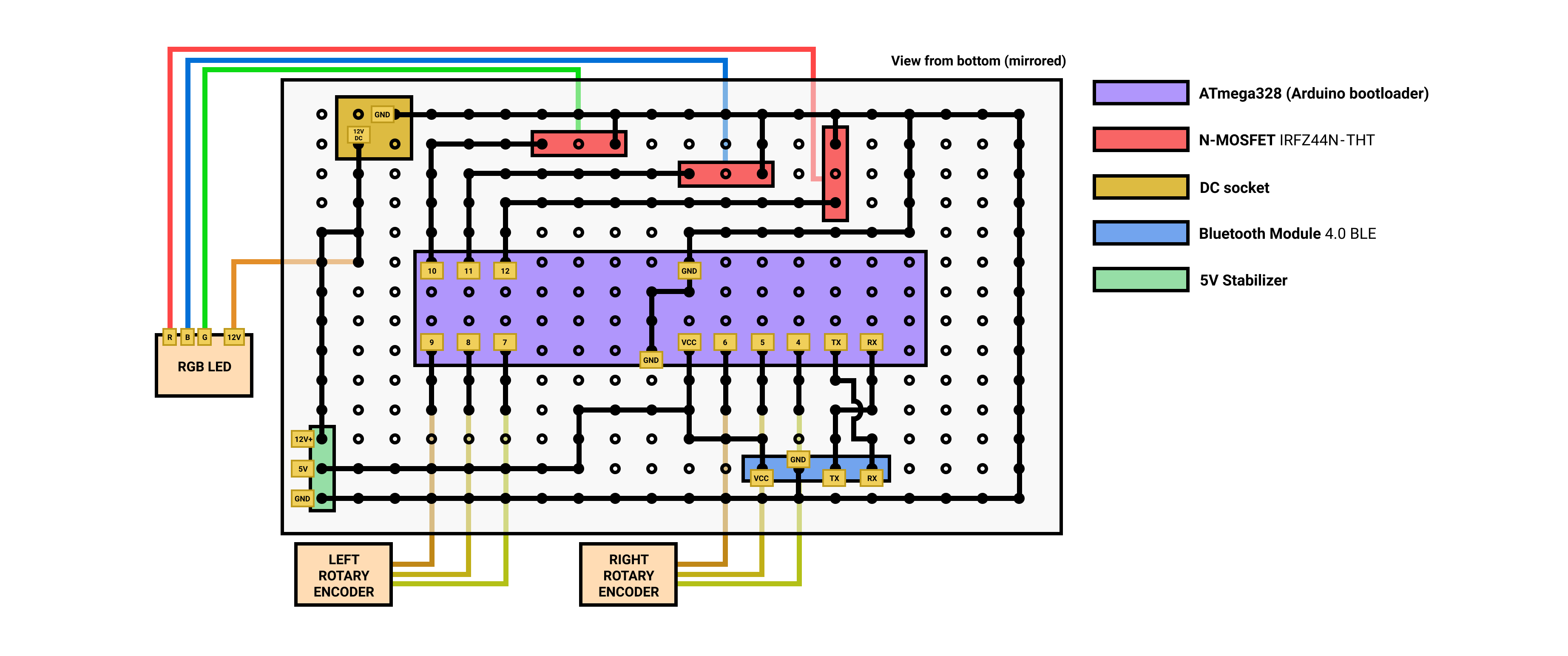
Representation of the created schema. In a real assembly, I had to adjust it a bit to fit all components, but it looks 90% as higher.
After about ten hours of soldering (still a beginner) and two burnt fingers (do not touch the components if something smells bad), I managed to get it to work! Everything went better than expected.
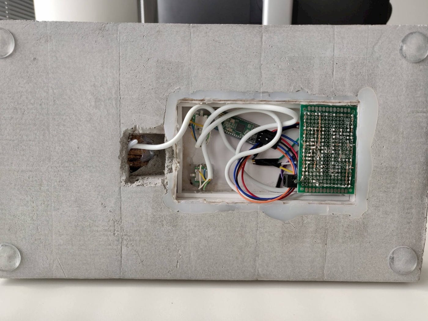
All parts combined. White cables are handles, small wires with black insulation are LED connections
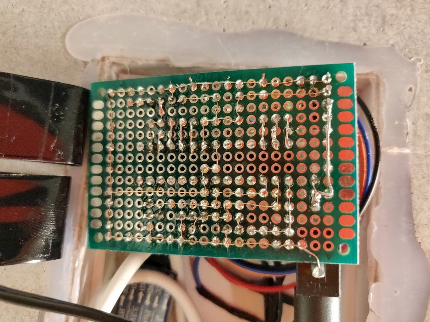
View from below. I used a thin copper wire to connect the joints
If you look close enough, you can see all the glue we used.
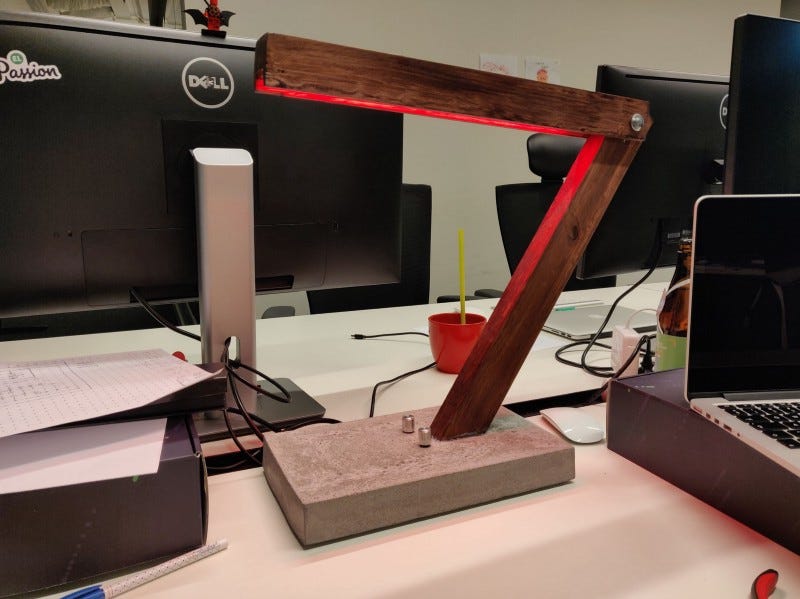
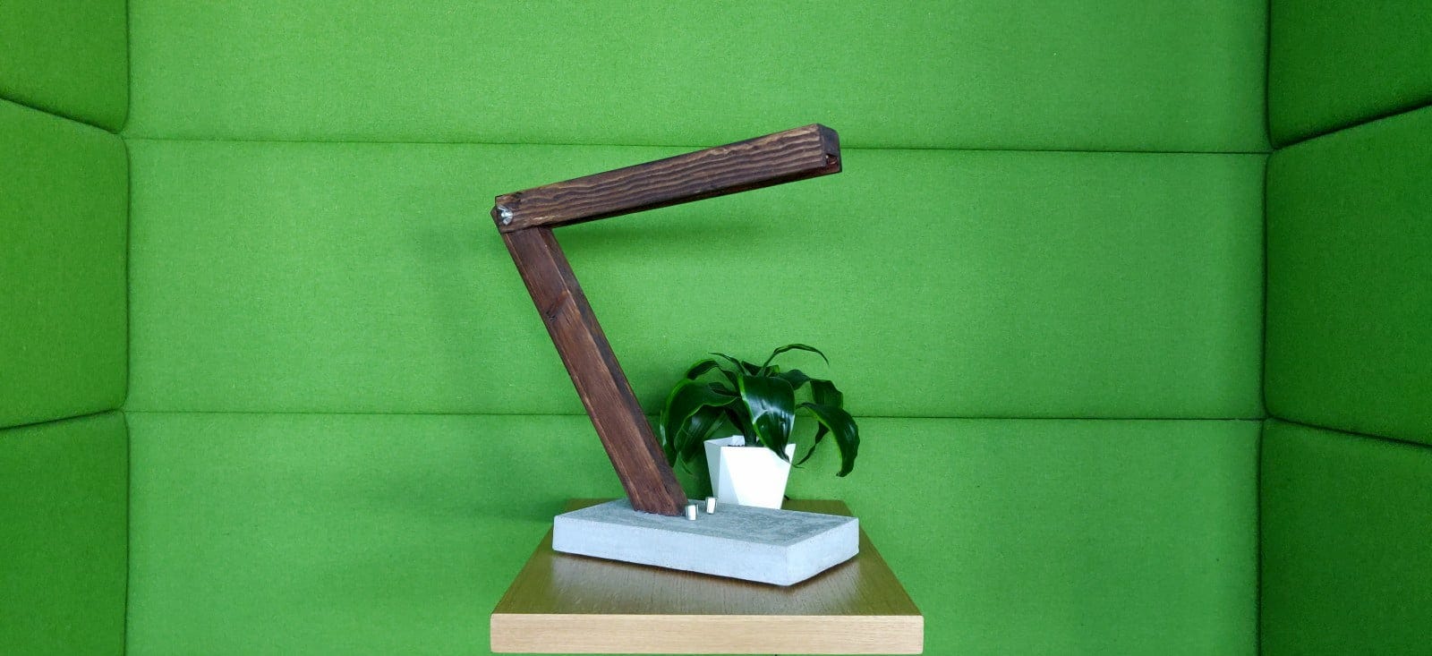
Ready product!
Watch a full demo where I will talk about all the features of this lamp. Despite several problems, for example, curved rotary knobs and incorrect display of colors, this works!
For me and, I hope, for the rest of the team, this was one of the most enjoyable hackathon projects. Both the process and the result were incredible, we had a lot of fun, and we learned a lot about working with wood, concrete and electronics.
If someone wants to create a similar lamp or needs more detailed information, do not hesitate to comment and ask me anything!