High-speed trains like the TGV no longer do with pneumatic braking
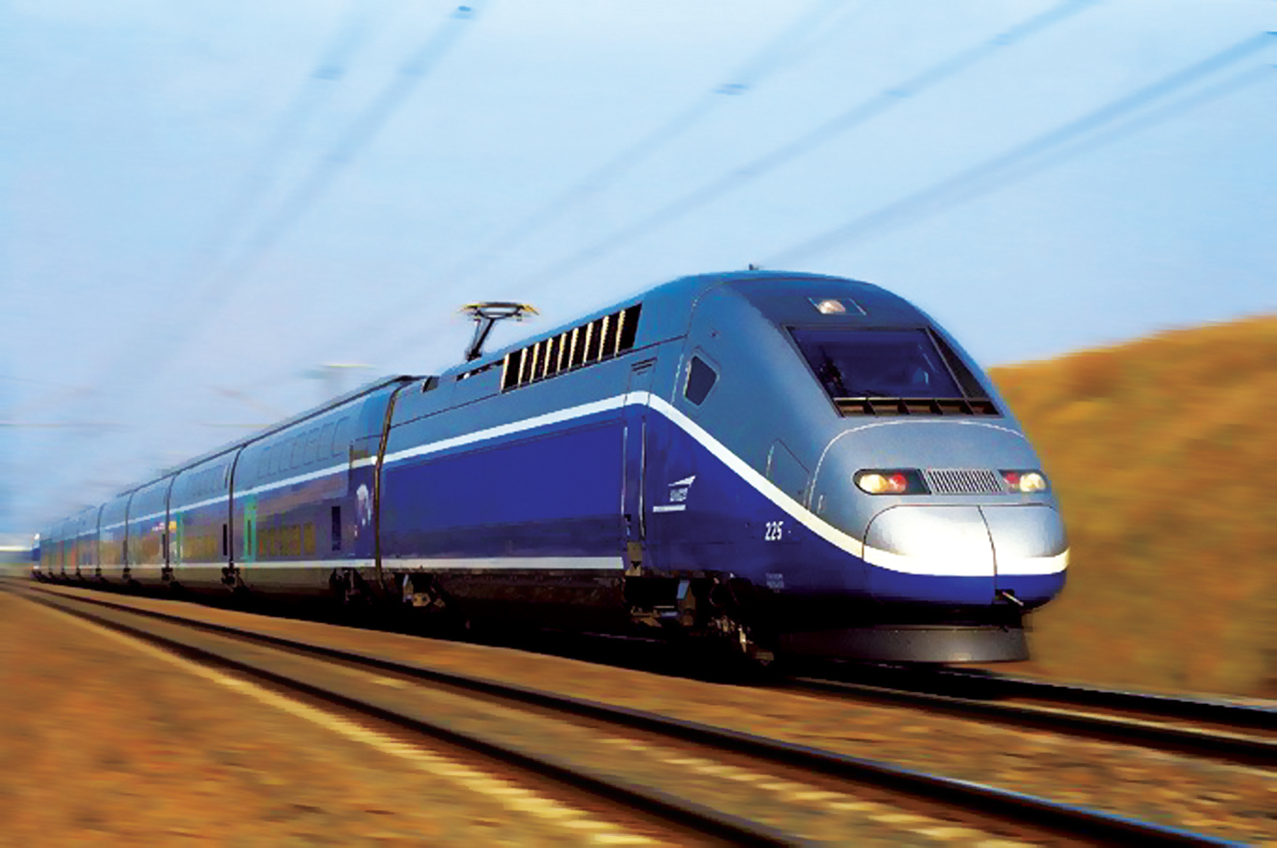
Today we will talk about the present, namely, what approaches to the creation of brake systems of rolling stock are used in the XXI century, literally a month later exchanging its third dozen.
1. Classification of rolling stock brakes
Based on the physical principle of creating braking force, all railway brakes can be divided into two main types: friction , using friction, and dynamic , using traction to create braking torque.
Friction brakes include shoe brakes of all designs, including disc brakes, as well as a magnetic rail brake , which is used in high-speed trunk transport, mainly in Western Europe. On track 1520, this type of brake was used exclusively on the ER200 electric train. As for the Sapsan, the Russian Railways refused to use the magnetic rail brake on it, although the prototype of this electric train, the German ICE3, is equipped with such a brake.
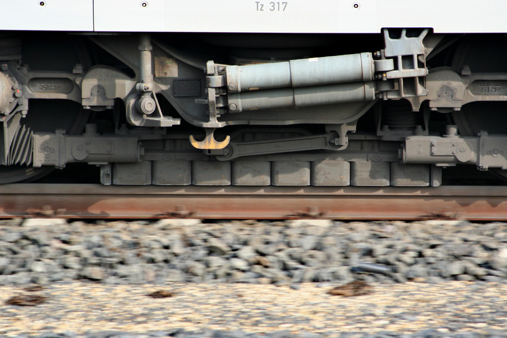
ICE3 train trolley with magnet rail brake
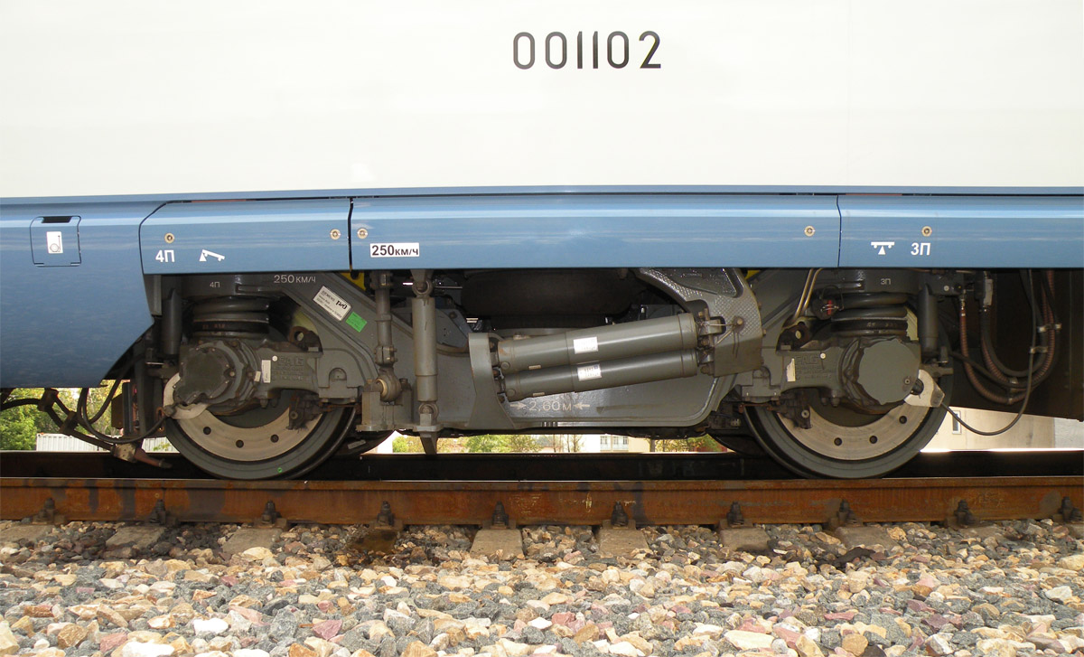
Cart of the Sapsan train
Dynamic brakes , or rather electrodynamic brakes, include all brakes whose action is based on the transfer of the traction motors to the generator mode ( regenerative and rheostatic brakes ), as well as braking by the anti-inclusion
With a regenerative and rheostatic brake, everything is relatively clear - the motors are in one way or another transferred to the generator mode, and in the case of recovery they transfer energy to the contact network, and in the case of a rheostat, the generated energy is burned on special resistors. Both of these brakes are used both on trains with locomotive traction and on motor-car rolling stock, where the electrodynamic brake is the main working brake, in view of the large number of traction motors distributed throughout the train. The only drawback of electrodynamic braking (EDT) is the impossibility of braking to a complete stop. When the efficiency of the EDT decreases, it is automatically replaced by a pneumatic friction brake.
As for the braking by the anti-inclusion, it provides braking to a complete stop, since it consists in reversing the traction motor on the go. However, this mode, in most cases, is emergency - its regular use is fraught with damage to the traction drive. If we take, for example, a commutator motor, then when the polarity of the voltage supplied to it changes, the counter-EMF arising in the rotating motor is not subtracted from the supply voltage but is added to it - the wheels both rotated and rotate in the same direction as in traction mode! This leads to an avalanche-like increase in current, and the best thing that can happen is that electrical protection devices will work.
For this reason, all measures are taken on locomotives and electric trains to prevent the reversal of engines on the go. The reversing handle locks mechanically when the driver's controller is in the running position. And on the same “Peregrine Falcons” and “Swallows”, turning the reversing switch at speeds above 5 km / h will lead to immediate emergency braking.
However, some domestic locomotives, such as the VL65 electric locomotive, use reverse braking as a standard mode at low speeds.
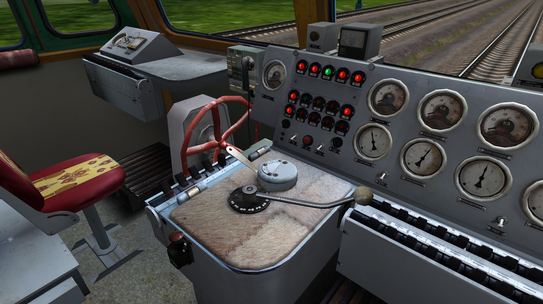
Reverse braking - standard, provided by the control system braking mode on the VL65 electric locomotive

I must say that despite the high efficiency of electrodynamic braking, any train, I always emphasize, is always equipped with a pneumatic brake of automatic action, that is, triggered by the release of air from the brake line. Both in Russia and around the world, the good old shoe friction brakes are on guard of traffic safety.
By functional purpose, friction-type brakes are divided into
- Parking, manual or automatic
- Train - pneumatic (PT) or electro-pneumatic (EPT) brakes installed on each unit of the rolling stock in the train and controlled centrally from the driver’s cab
- Locomotive - direct-acting pneumatic brakes designed to brake the locomotive without braking the train. They are managed separately from the train.
2. Parking brake
A manual brake with a mechanical drive has not disappeared from the rolling stock, it is installed both on locomotives and on cars - it just changed the specialty, namely, it turned into a parking brake, which eliminates the spontaneous movement of rolling stock in the event of air leaving its pneumatic system. A red wheel similar to a ship steering wheel is a hand brake drive, one of its variants.
Manual parking brake steering wheel in the cabin of an electric locomotive VL60pk
Hand brake in the vestibule of a passenger car
Hand brake on a modern freight car
A manual brake with the help of a mechanical drive presses the same pads to the wheels that are used during normal braking.
On modern rolling stock, in particular on the EVS1 / EVS2 Sapsan, ES1 Swallow electric trains, as well as on the EP20 electric locomotive, the parking brake is automatic and the pads are pressed against the brake disk by spring-loaded energy accumulators . Some tick-borne mechanisms that press the pads to the brake discs are equipped with powerful springs, and so powerful that tempering is carried out by a pneumatic actuator with a pressure of 0.5 MPa. The pneumatic actuator, in this case, counteracts the springs pressing the pads. Such a parking brake is controlled by buttons on the driver’s console.
Buttons for controlling the parking spring brake (SPT) on the ES1 "Swallow" electric train
In its structure, such a brake is similar to that used on powerful trucks. But such a system is completely unsuitable as the main brake in trains, and why, I will explain in detail after talking about the operation of train pneumatic brakes.
3. Cargo-type pneumatic brakes
Each freight car is equipped with the following set of brake equipment
Brake equipment of a freight car: 1 - brake connecting sleeve; 2 - end crane; 3 - stop crane; 5 - dust collector; 6, 7, 9 - air distribution modules conv. No. 483; 8 - uncoupling tap; BP - air distributor; - brake line; - reserve tank; TC - brake cylinder; AR - cargo auto mode
The brake line (TM) is a pipe with a diameter of 1.25 '' running along the entire carriage, at the ends it is equipped with end cranes to disconnect the brake line when the car is uncoupled before disconnecting the flexible connecting arms. In the brake line, the so-called charging pressure of 0.50 - 0.54 MPa is maintained in normal mode, so it is dubious to disconnect the sleeves without closing the end valves, which can literally deprive you of your head.
The supply of air directly supplied to the brake cylinders is stored in a reserve tank (ZR), the volume of which in most cases is 78 liters. The pressure in the spare tank is exactly equal to the pressure in the brake line. But no, this is not 0.50 - 0.54 MPa. The fact is that such pressure will be in the brake line on the locomotive. And the farther from the locomotive, the lower the pressure in the brake line, because inevitably there are leaks in it leading to air leaks. So the pressure in the brake line of the last car in the train will be slightly less than the charging one.
The brake cylinder , and on most wagons it is single, when filling it from the spare tank, presses all the pads on the wagon to the wheels through the brake linkage. The volume of the brake cylinder is about 8 liters, therefore, with full braking, a pressure of not more than 0.4 MPa is set in it. The pressure in the spare tank is reduced to the same value.
The main “actor” in this system is the air distributor . This device reacts to pressure changes in the brake line, performing one or another operation depending on the direction and rate of change of this pressure.
When the pressure in the brake line decreases, braking occurs. But not with any decrease in pressure - a decrease in pressure should occur at a certain rate, called the pace of service braking . This rate is provided by the driver’s crane in the locomotive cab and ranges from 0.01 to 0.04 MPa per second. When the pressure decreases at a slower pace, braking does not occur. This is done so that the brakes do not work during standard leaks from the brake line, and also do not work when eliminating supercharged pressure, which we will talk about later.
When the air distributor responds to braking, it performs additional discharge of the brake line at a service pace of 0.05 MPa. This is done in order to ensure a steady decrease in pressure along the entire length of the train. If additional discharge is not done, then the last cars of a long train may not slow down in principle. Additional discharge of the brake line is performed by all modern air distributors, including passenger ones.
When triggered by braking, the air distributor disconnects the spare tank from the brake line and connects it to the brake cylinder. The brake cylinder is filled. It occurs exactly as long as the pressure drop in the brake line continues. When the pressure drop in the TM ceases, the filling of the brake cylinder stops. The overlapping mode comes. The pressure accumulated in the brake cylinder depends on two factors:
- depth of discharge of the brake line, i.e. the magnitude of the pressure drop in it relative to the charging
- air distribution mode
The cargo air distributor has three operating modes: loaded (G), medium (C) and empty (P). These modes differ in the maximum pressure accumulated in the brake cylinders. Switching between modes is carried out manually by turning the special mode knob.
To summarize, the dependence of the pressure in the brake cylinder on the depth of discharge of the brake line with a 483 air distributor in various modes looks like this

The disadvantage of using the mode switch is that the wagon operator must go along the entire train, climb under each car and switch the mode switch to the desired position. This is done, according to rumors coming from operation, not always. Excessive filling of the brake cylinders on an empty wagon is fraught with a load, a decrease in the efficiency of braking and damage to wheelsets. To overcome this situation on freight cars, between the air distributor and the brake cylinder, the so-called auto mode (AR) is switched on, which, mechanically determining the weight of the car, smoothly adjusts the maximum pressure in the brake cylinder. If the car is equipped with auto mode, then the mode switch on BP is set to the "loaded" position.
Braking is usually performed in steps. The minimum discharge stage of the brake line for BP483 will be 0.06 - 0.08 MPa. At the same time, a pressure of 0.1 MPa is set in the brake cylinders. In this case, the driver puts the crane in the overlapping position, at which the pressure set after braking is maintained in the brake line. If braking efficiency from one stage is not enough, the next stage is performed. At the same time, the air distributor doesn’t care how fast the discharge occurs - when the pressure decreases at any rate, the brake cylinders are filled in proportion to the pressure drop.
Complete release of the brakes (complete emptying of the brake cylinders on the entire train) is carried out by increasing the pressure in the brake line above the charging line. Moreover, on freight trains, a significant overpressure in the TM is performed over the charging one, so that the wave of pressure increase reaches the latest cars. The full brake release in a freight train is a long process and can take up to a minute.
BP483 has two vacation modes: plain and mountain. In plain mode, with increasing pressure in the brake line, a complete, stepless vacation occurs. In mountain mode, stepwise release of the brakes is possible, which is not a complete emptying of the brake cylinders. This mode is applied when moving along a complex profile with a large amount of slopes.
The 483 air distributor is generally a very interesting device. A detailed analysis of his device and work is a topic for a separate large article. Here we examined the general principles of the operation of a cargo brake.
3. Passenger-type air brakes
Brake equipment of a passenger car: 1 - connecting sleeve; 2 - end crane; 3, 5 - junction boxes of the electro-pneumatic brake line; 4 - stop crane; 6 - a tube with an electro-pneumatic brake wiring; 7 - insulated suspension of the connecting sleeve; 8 - dust collector; 9 - outlet to the air distributor; 10 - uncoupling tap; 11 - working chamber of the electric air distributor; - brake line; BP - air distributor; EVR - electric air distributor; TC - brake cylinder; ZR - reserve tank
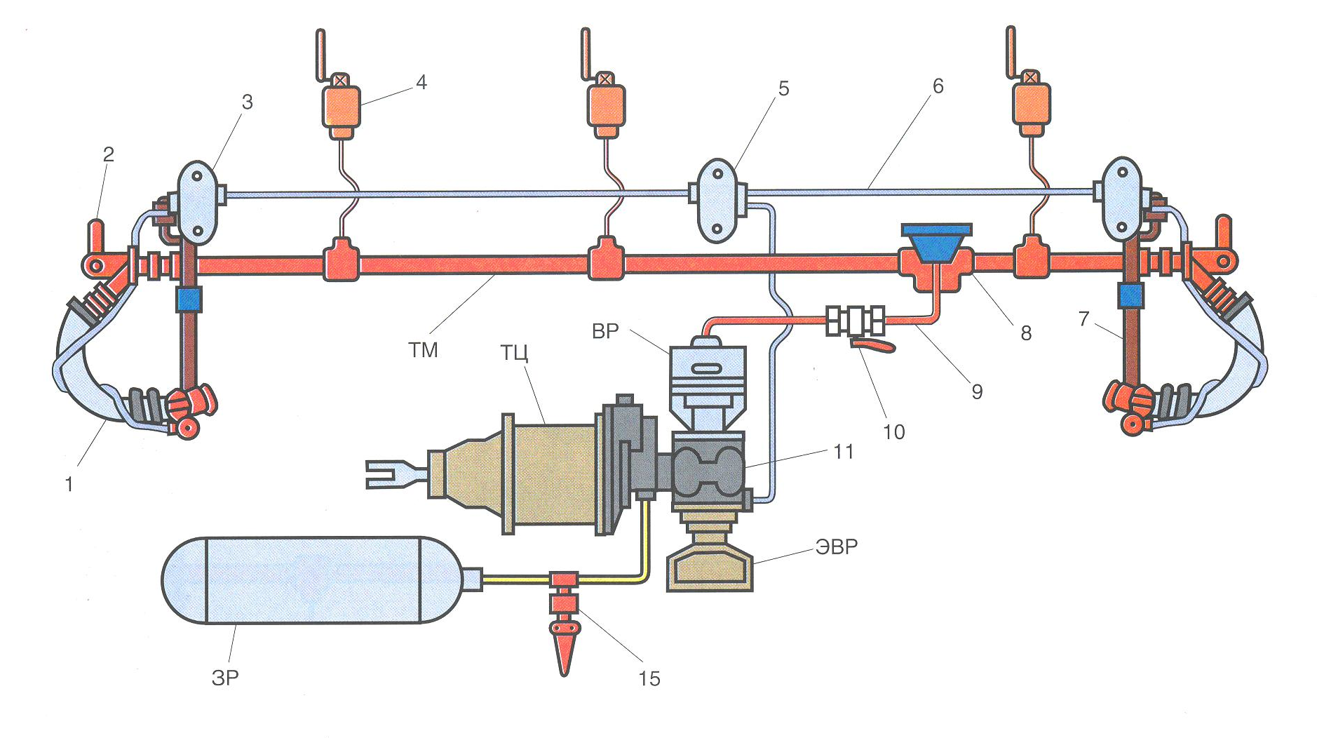
A large amount of equipment immediately catches your eye, starting with the fact that there are already three stop-cranes (one in each vestibule, and one in the compartment of the conductor), ending with the fact that domestic passenger cars are equipped with both pneumatic and electro-pneumatic brakes (EPT) .
An attentive reader will immediately notice the main drawback of pneumatic brake control - the final propagation speed of the brake wave, limited from above by the speed of sound. In practice, this speed is lower and is 280 m / s for official, and 300 m / s for emergency braking. In addition, this speed is highly dependent on air temperature and in winter, for example, it is lower. Therefore, the eternal companion of pneumatic brakes is the unevenness of their response in composition.
The uneven response leads to two things - the appearance of significant longitudinal reactions in the train, as well as an increase in stopping distance. The first is not so typical for passenger trains, although containers with tea and other drinks jumping on a table in a compartment will not please anyone. Increasing the braking distance is a serious problem, especially in passenger traffic.
In addition, the domestic passenger air diffuser is like an old conv. No. 292, and the new conv. No. 242 (which, by the way, is becoming more and more in the fleet of passenger cars), both of these devices are direct heirs of the Westinghouse triple valve, and they work on the difference of two pressures - in the brake line and the spare tank. They are distinguished from the triple valve by the overlapping mode, that is, the possibility of stepwise braking; the presence of additional discharge of the brake line during braking; the presence in the design of an emergency braking accelerator. These air distributors do not provide step-by-step tempering - they give immediately complete tempering as soon as the pressure in the brake line exceeds the pressure in the spare tank that has settled there after braking. A stepped holiday is very useful when adjusting braking for an exact stop at the landing platform.
Both problems - uneven operation of the brakes and the absence of stepwise release, on a track of 1520 mm are solved by installing an electrically operated air distributor (EVR) on the railcars with electric control, conv. No. 305.
Domestic EPT - electro-pneumatic brake - direct-acting, non-automatic action. On passenger trains with locomotive traction EPT operates on a two-wire circuit.
Block diagram of a two-wire EPT: 1 - control controller on the crane operator; 2 - rechargeable battery; 3 - static power converter; 4 - panel of control lamps; 5 - control unit; 6 - terminal block; 7 - connecting heads on the sleeves; 8 - insulated suspension; 9 - semiconductor valve; 10 - tempering solenoid valve; 11 - brake solenoid valve.
Two wires stretch along the whole train: No. 1 and No. 2 in the figure. On the tail carriage, these wires are electrically connected to each other and, on the resulting loop, they send alternating current with a frequency of 625 Hz. This is done to control the integrity of the EPT control line. When the wire is broken, the AC circuit breaks, the driver receives a signal in the form of extinction in the cockpit of the warning lamp "O" (vacation).
The control is conducted by direct current of different polarity. In this case, the rails are the wire with zero potential. When a positive voltage (relative to the rail) voltage is applied to the EPT wire, both electromagnetic valves installed in the electric air distributor are activated: tempering (OV) and braking (TV). The first of them isolates the working chamber (RK) of the electric air distributor from the atmosphere, the second - fills it from the spare tank. Further, the pressure switch installed in the EVR, working on the pressure difference in the working chamber and the brake cylinder, comes into play. When the pressure in the RK exceeds the pressure in the shopping center, the latter is filled with air from the spare tank to the pressure that has been accumulated in the working chamber.
When negative potential is applied to the wire, the brake valve turns off, since the current to it is cut off by the diode. Only the release valve that holds the pressure in the working chamber remains active. So the position of the overlap is realized.
When the voltage is released, the release valve loses power, opens the working chamber to the atmosphere. When the pressure in the working chamber decreases, the pressure switch also releases air from the brake cylinders. If, after a short vacation, the driver’s crane is again in the shut off position, then the pressure drop in the working chamber will stop, and the air discharge from the brake cylinder will also stop. In this way, a stepwise release of the brake is achieved.
What happens when a wire breaks? That's right - EPT will let go. Therefore, this brake (on domestic rolling stock) is non-automatic. When EPT fails, the driver has the opportunity to switch to pneumatic brake control.
EPT is characterized by the simultaneous filling of brake cylinders and their emptying throughout the train. The rate of filling and emptying is quite high - 0.1 MPa per second. EPT is an inexhaustible brake, since during its operation the usual air distributor is in the holiday mode and feeds the spare tanks from the brake line, which in turn is fed by the driver’s crane on the locomotive from the main tanks. Therefore, it is possible to slow down the EPT at any frequency required for operational control of the brakes. The possibility of stepwise release allows you to control the speed of the train very accurately and smoothly.
Pneumatic brake control of a passenger train is not much different from a cargo brake. There is a difference in control methods, for example, the release of the pneumatic brake is made up to the charging pressure, without overstating. In general, excessive pressure overestimations in the brake line of a passenger train are fraught with troubles, therefore, when the EPT is completely released, the pressure in the TM is inflated by a maximum of 0.02 MPa over the set charging pressure.
The minimum depth of TM discharge during braking on a passenger brake is 0.03 - 0.05 MPa, while a pressure of 0.1 - 0.15 MPa is created in the brake cylinders. The maximum pressure in the brake cylinder of a passenger car is limited by the volume of the spare tank and usually does not exceed 0.4 MPa.
Conclusion
Now I will turn to some commentators who are surprised (and, in my opinion, even indignant, but I can’t say anything) the complexity of the train brake. In the comments, it is proposed to apply an automobile circuit with energy accumulators. Of course, it is from a sofa, or a computer chair in an office, through a browser window, many problems are more visible and their solution is more obvious, but I will allow myself to note that most of the technical solutions adopted in the real world have a clear justification.
As already mentioned, the main problem of the pneumatic brake in the train is the final speed of the pressure drop jump along the long (up to 1.5 km in a train of 100 wagons) brake pipe - brake wave. To accelerate this brake wave, an additional discharge is required by the air distributor. There will be no air distributor, there will be no additional discharge. That is, the brakes on the energy accumulators will obviously be noticeably worse in terms of uniformity of response, returning us to the time of Westinghouse. A freight train is not a truck, there are different scales, and therefore other principles of brake control. I am sure that this is not just so, and the direction of world inhibitory science did not accidentally go along the path that led us to such constructions. Dot.
This article is a kind of overview of brake systems existing on modern rolling stock. Further, in other articles of this series I will dwell on each of them in more detail. We will find out what devices are used to control the brakes, how air diffusers are arranged. Let us consider in more detail the issues of regenerative and rheostatic braking. And of course, consider the brakes of high-speed transport. See you soon and thank you for your attention!
PS: Friends! Special thanks I want to say for the mass of personal messages indicating errors and typos in the article. Yes, I am a sinner who is not friends with the Russian language and gets confused on the keys. I tried to correct your comments.