Greetings, dear ones!
“Hydroacoustic hydrophone cut” ©
From our previous articles, the situation has not fundamentally changed: we still have not explored most of the world's ocean
So, I strengthen how I can.
Today I will talk in detail and “on fingers” about the different types of underwater navigation systems according to the established incorrect classification, what they are, what are the pros and cons, in general, in which case where to run, what to press and where to turn.
Achtung: traces of matan may be present in the article!
If the calm waters of your soul stirred up this signal, welcome to kat!
When it comes [1] to acoustic positioning systems, their type is always indicated as USBL, LBL, SBL. “BL” here means Baseline, i.e. baseline. Here I propose and start.
What is the baseline?
The baseline is formed by two reference points, the relative position of which is known at a given point in time. The first picture shows how these reference points together with the desired one determine the set of spatial triangles ( ), the basis of which is the baseline ( )
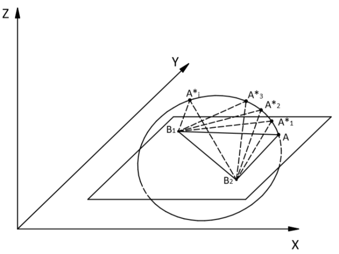
The baseline defines the desired point on the circle
The triangle is defined by:
- or on the base and two ranges, measured from both reference points to the desired one, in this case we are talking about trilateration;
- or at the base and two corners, which is called triangulation.
Lyrical digression
While writing an article, I was thinking about how I got into it at all.
I remembered that as a child I watched a movie where in the post-apocalyptic world people hunted dragons (which caused the apocalypse), for which they calculated their location in the air, placed “beacons” on the ground, and I have clearly learned since that for a complete picture of the lighthouses needed three. The word "triangulation" is firmly rooted in the teenage brain. I remember what I thought then: how cool it would be to be a developer of such things.
Actually, well, here I am!
The definition of a triangle means the determination of the coordinates of the desired point.
The use of triangles in determining location originates from the depths of centuries and the first references are already in the works of Thales [2] and Euclid [3] .
One baseline gives many triangles whose vertices lie on a circle. And to determine the location of the desired point in n-dimensional space, n + 1 baselines are required. The number of required baselines can be reduced to n if one of the coordinates of the desired point is known, for example, the depth (or
The above definition of the baseline is usually referred to the methods of triangulation and trilateration, however, it can be extended to the multilateration method [4].
In this case, the angles and ranges to the desired point are unknown, but the difference between the latter is known (for example, the moment of emission of the signal by the desired object is unknown, but the moments of its arrival at both reference points are known and measured by synchronized clocks, i.e., the delay between the arrival of the signal at reference points).
The signal arrival time multiplied by the signal propagation speed is called pseudorange.
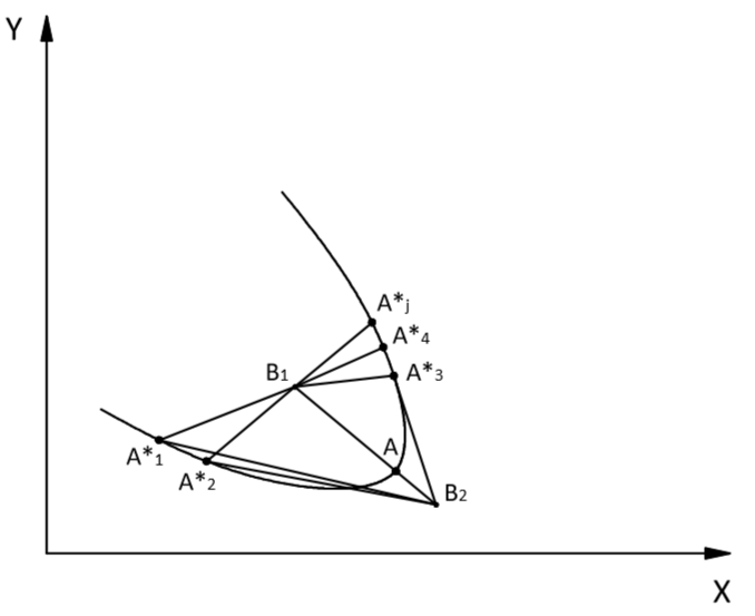
The baseline for multilateration determines the desired point on the hyperbole
From the picture above it is easy to see that in this way an infinite number of triangles can be defined ( ) whose vertices representing the position of the desired point lie on the hyperbole. In this case, the control points will be the focal points of the hyperbola.
Here, as in the case of triangulation, the position of the desired point is completely determined by n + 1 baselines for n-dimensional space.
Bad word for export controls
The fact is that, depending on the location of the coordinates, there are two classes of systems:
- actually navigation (directly called navigation systems), where the coordinates are generated on the object itself (such as in GPS).
- tracking systems (surveillance), when for example there is some kind of a beacon on the object and we are bearing it.
So, for export control, this word is very bad and not suitable, which was tragically verified by our own experience. To explain to the bureaucratic machine that this is "not at all what you thought" is very difficult and since then we have called such systems positioning systems.
Nerdy vogue he
In view of the ambiguities of the translation, it is worth mentioning that the positioning system should not be confused, for example, with the so-called. dynamic positioning in ships, dynamic positioning systems (Eng. DP, Dynamic positioning), this is generally from an adjacent area, but means a little different - systems that allow a ship to maintain its geographical position and orientation (heading), “hover” in one place.
Generally accepted classification according to the relative size of the baseline and its incompleteness
Now back to the first letters of the abbreviations USBL, LBL and SBL. They determine the relative size of the baselines.
In general, it is determined relative to the maximum size of the possible trajectory of a positioned object.
If it’s quite simple to explain, for example, we
Nerdy vogue he
For all severity, it is necessary to mention that the diver’s trajectory is meant in the coordinate system associated with the measuring base. Those. if we follow a diver from a rubber boat of a support vessel and drift along with it, then in principle we can drift a few kilometers (in reality, of course, this cannot be with divers, but with a remote-controlled robot - completely). And the trajectory relative to our ship is estimated.
It is clear that the classification attribute is so-so, and I completely agree. Nevertheless, the generally accepted classification is structured that way. And they distinguish:
- USBL, ultra-short baseline - ultrashort-base systems, where the dimensions of the baselines are much smaller than the trajectory of the positioned object and
- SBL, short baseline - short-base systems where the dimensions of the baselines are comparable to the trajectory of a positioned object,
- LBL, long baseline - long-baseline systems where the dimensions of the baselines significantly exceed the dimensions of the trajectory of the positioned object.
There is a certain ambiguity in the choice of class between short- and long-base systems, and often, as one of the signs of short-base systems, they indicate a rigid connection of supporting elements with each other - for example, when they are fixed on a ship. The supporting elements of the long-base system are kinematically not connected in any way, i.e. changes in their positions in space are uncorrelated.
We now consider all three types and some of their combinations in more detail in terms of their strengths and weaknesses.
Ultrashort-base systems
As the name implies, the baseline in ultrashort-base systems (UKB systems) is much smaller than the trajectory of the positioned object.
As a rule, in most existing (for example, this [5] , this [6] and this [7] ) UHF systems, the size of the baselines is from units to tens of centimeters. Most of them are goniometric systems - i.e. systems that determine the angle of arrival of the signal of the beacon-responder or pinger.
In terms of layout, such systems consist of:
- a base station - a device containing a multi-element receiving antenna, the individual elements of which form either a phased antenna array, in this case, the angle of arrival is determined from the phase difference of the incoming signal between the individual elements, or a set of baselines, also formed by pairs of individual elements, in in this case, the angle of arrival is determined by different delays in the arrival of the signal to the elements;
In order not to fiddle with the copyright to the pictures, I will give our Zima-Base as an example of a base station:
On the table:
In the working moment:

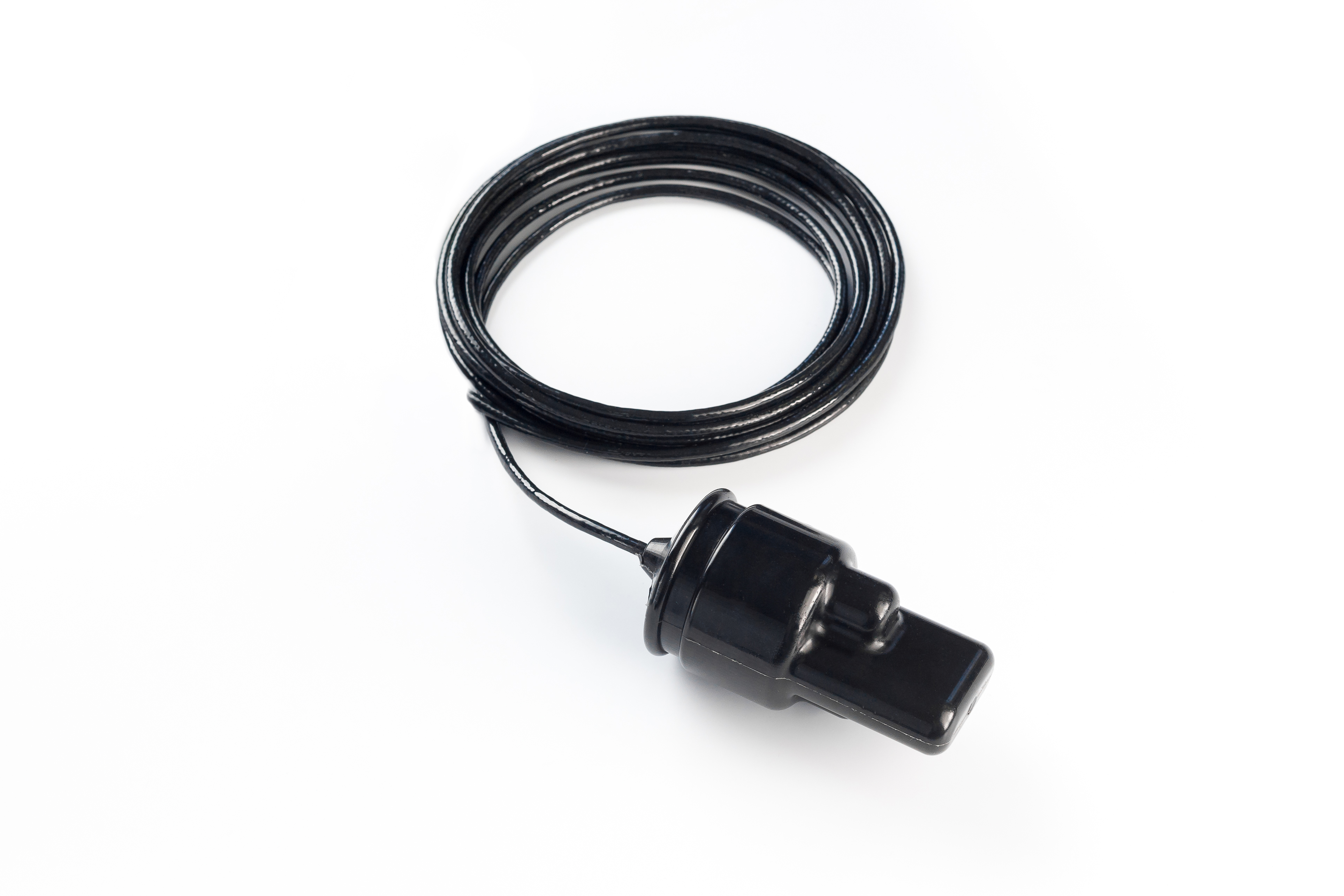
- responder beacons responding to a request from the base station, which in turn allows determining the propagation time of the signal between the beacon and the base station (slant range) or pingers, in contrast to responder beacons, emitting a signal at regular intervals. Pinger can be pre-synchronized with the base station, which allows one-way measurement of propagation time.
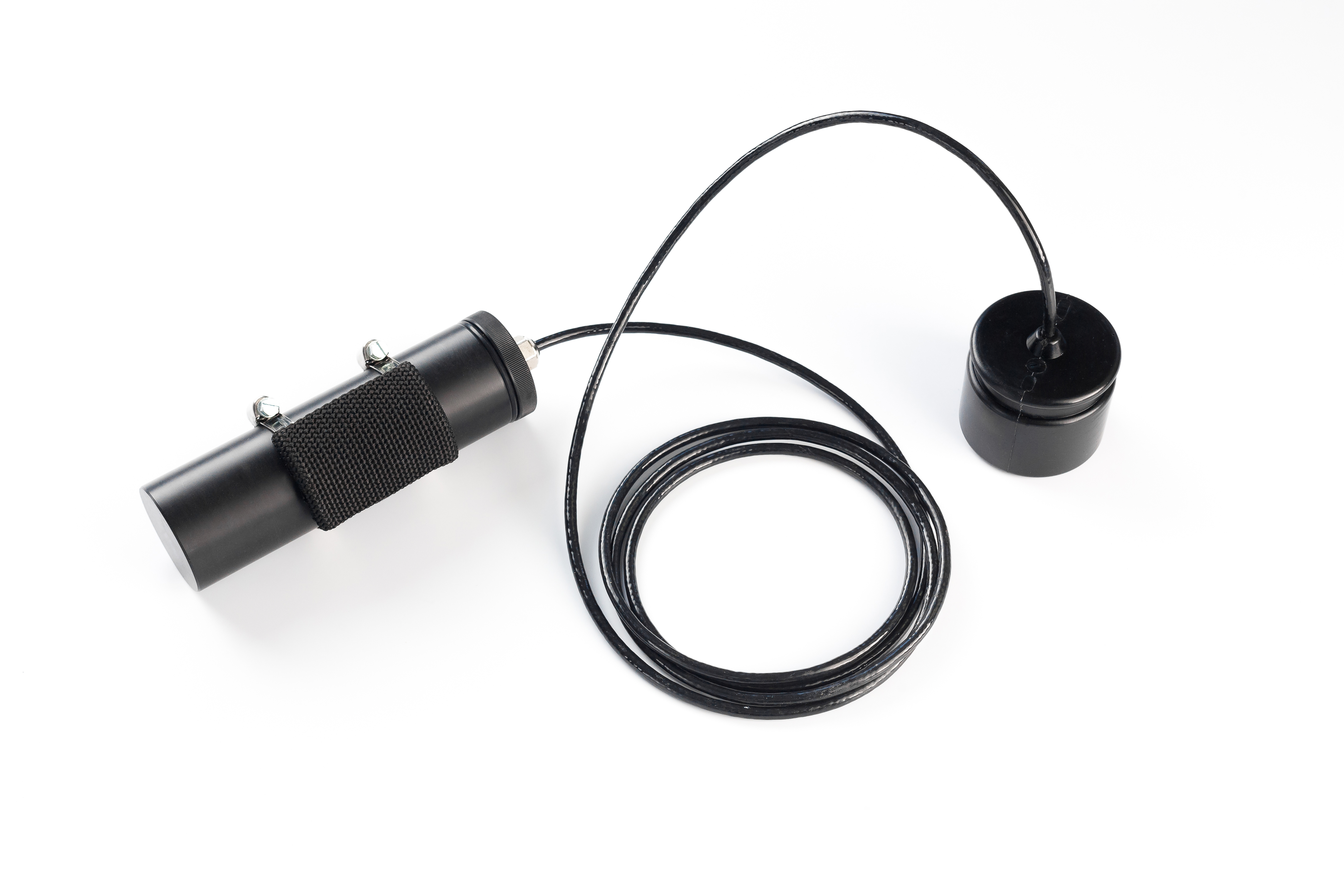
As an example, I’ll again cite the beacon-responder of our Zima system:
Stand-alone with battery canister:
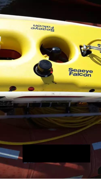
On board TNLA:
There are also systems where transponders are electrically coupled to a base station and the interrogation signal is supplied as an electric gate pulse.
Thus, the class of UKB systems is represented by a fairly wide range of various specific executions, and often the inclusion of a system in UKB does not provide enough information about the specific method of its operation.
The following picture illustrates the generalized principle of operation of UKB systems.
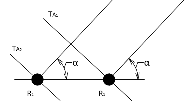
Demonstration of the principle of operation of systems that determine the angle of arrival of a signal
The figure above shows a pair of antenna array transducers that receive a flat signal front. From a known distance between transducers and measured delay determined by the angle signal arrival.
The obvious advantages of UKB systems include the small required composition of equipment and the rapid deployment of the system.
In the general case, the responder or pinger can be
In some practical cases, the use of UKB systems is uncontested. For example, when a search is made for something
However, UKB systems have certain serious drawbacks. For example, to determine the position of a positioned object in absolute coordinates, the base station itself must be fully defined in space: it is necessary to know not only its geographical position but also the orientation of the array of receivers in space: azimuthal angle, roll and trim angles.
That is, from a structural point of view, the UHF system should include not only a multi-element antenna array, which in itself is quite complex structurally, but also devices that can determine its position in space - tilt sensors along two horizontal axes and a sensor heading - magnetic or GNSS compass. If the direction-finding antenna is installed on something underwater, then, accordingly, the possibility of using the GNSS compass is closed.
Moreover, since the position of the desired object is estimated either by two angles of arrival of the signal (horizontal and vertical) or by the horizontal angle and depth (which is fashionable and progressive) transmitted in the signal of the responder or pinger, it is obvious that the final angular accuracy systems will provide increasing with a range of both the error in the determined position of the positioned object, growing with distance proportional to the tangent of the angular error, as illustrated in the following picture:
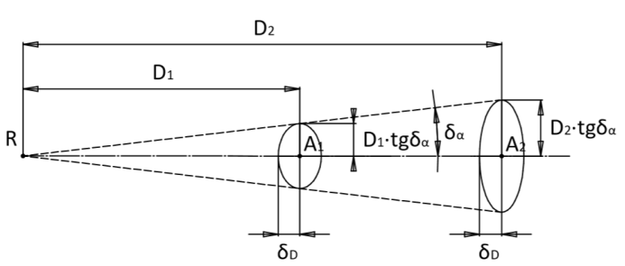
Influence of the angular accuracy of UKB systems on the error in determining the position of an object
The figure above shows the spread of the determined location of the signal source. One of the semi-axes of the ellipse determined by the error in measuring the distance, and the other, as where D is the distance (slant range) to the source.
Moreover, in the case of ambiguity and the impossibility of guaranteed identification of a direct beam (a beam - read the signal front, direct call the one that came directly from the source, without reflecting from anything), the UHF systems as a whole are very much influenced by multipath propagation, especially if there are reflections from the coastline or any elements of the underwater landscape.
In other words, in the presence of powerful reflected signals coming from other directions (up to the opposite), the UHF system is not immune to accepting such a signal as direct (since in general this problem is unsolvable - the sum of reflected signals can be more powerful, “louder” than the direct one) sometimes in practice), which leads to completely incorrect results in solving the navigation problem.
Newer systems use direct measurement of the depth of the transponder or pinger, while older systems determine the position at two angles. The fact is that the vertical angle has the least certainty, because the sound as a whole can undergo multiple bottom-surface reflections, and its definition is relevant only at the smallest distances. This is shown in the picture below, where the vertical section of the channel is shown in the upper image, and it can be seen that when determining the vertical angle from one of the reflected signals, the error can be completely unacceptable. At the same time, on the lower part of the figure, where a top view is shown, it is seen that all the reflected signals come from the same horizontal direction.
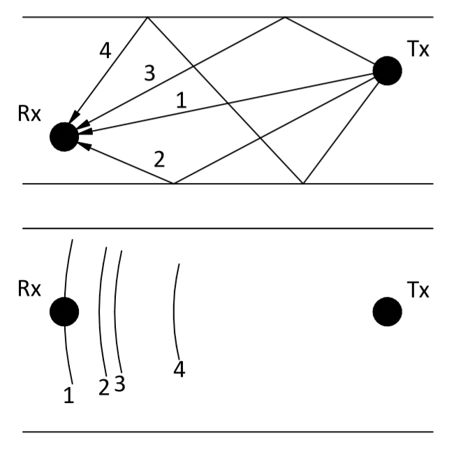
Different accuracy in determining horizontal and vertical angles in UKB systems
Summarizing the discussion of UCB systems, we can say that their area of application is where it is difficult, unjustified or impossible to use other types of navigation systems and positioning systems.
Manufacturers of modern UKB systems report angular accuracy of their products up to 0.03 ° (1σ) [8] .
Their advantage: deployment speed and versatility.
From the experience of communicating with users, I can say that everyone around wants only UKB just because of the speed of deployment. And no matter how much I explain, no matter how much I write, everyone nods, but they still want to use the UCB. As the saying goes: "do not forget to suffer."
Some inexperienced generally use the abbreviation USBL as a designation for any underwater positioning system.
Nerdy vogue he
An even more curious curiosity is when any sonar thing is called a sonar. We are literate guys and remember that a sonar is like a radar, only with sound, that is, sonar, but this is a completely different story.
Short base systems
Short-base systems in the vast majority of cases are located on the hulls of specialized vessels. That is, the dimensions of the baselines are comparable to the dimensions of the vessel.
At present, the accuracy of UKB systems is quite high, and the convenience of use looks much more profitable than for KB, which led to crowding out KB systems from widespread use, and the tasks solved by KB systems now include only those that have specific conditions that do not allow apply UKB system.
However, in the past, design bureaus were used, for example, to escort the Triest-1 bathyscaphe to the place of the death of the US Navy submarine "Thresher" (eng. USS Thresher). The SHARPS SBL KB system was used at the Woods hole Oceanographic Insititution to accompany the deep-sea vehicle JSON to its lowering stand MEDEA, the achieved positioning accuracy of 0.09 m is reported [9].
Of modern KB systems, we can note this one [10] , positioned by the manufacturer as “Underwater GPS”, and distributed as a designer.
In order for the eye to catch on and feel all the charm and “simplicity” of deployment, I’ll give a couple of pictures from our recent tests of the prototype KB system for parking an autonomous underwater vehicle:
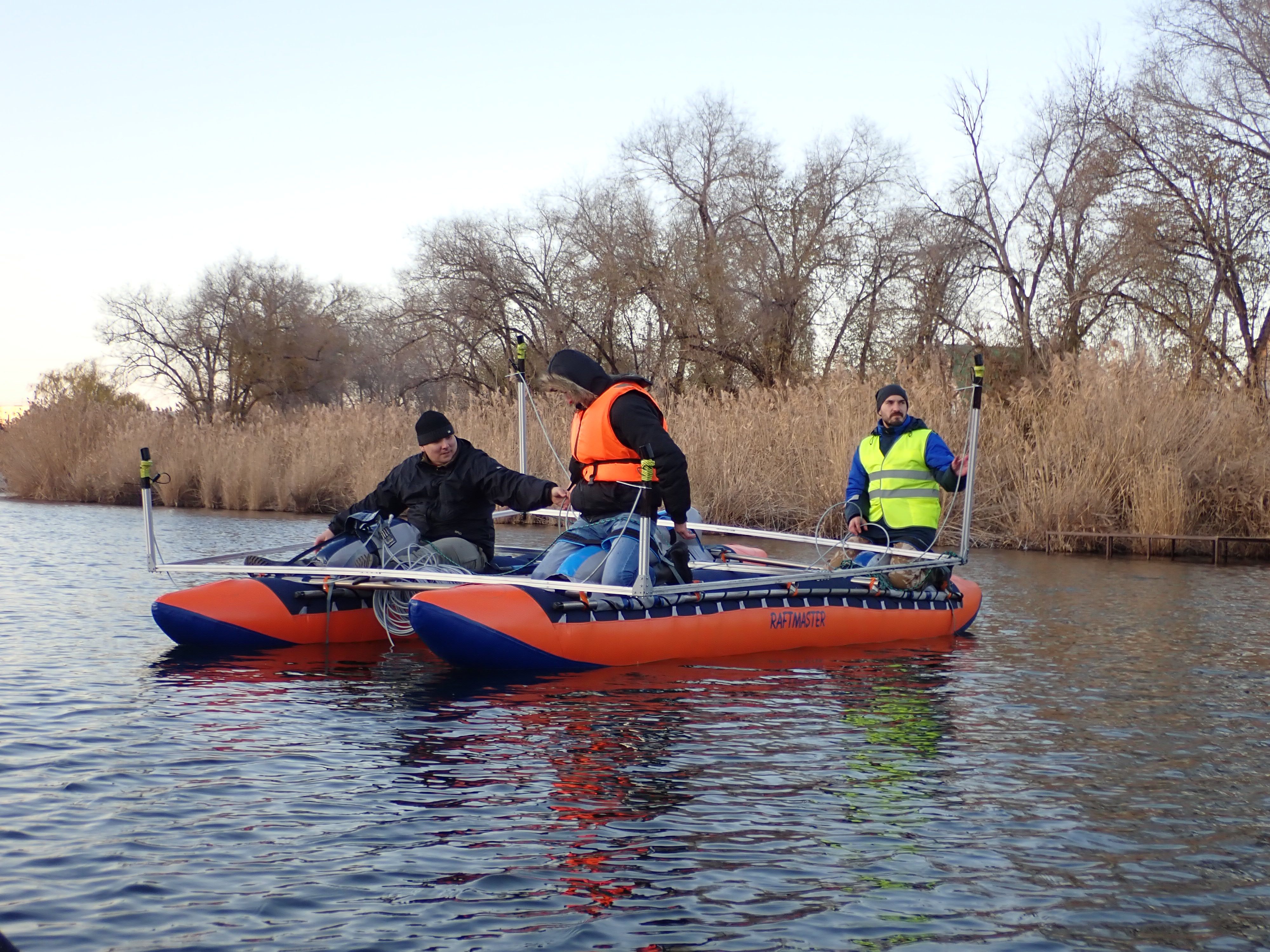
The aluminum frame is the short base. You can imagine the convenience of launching this design.
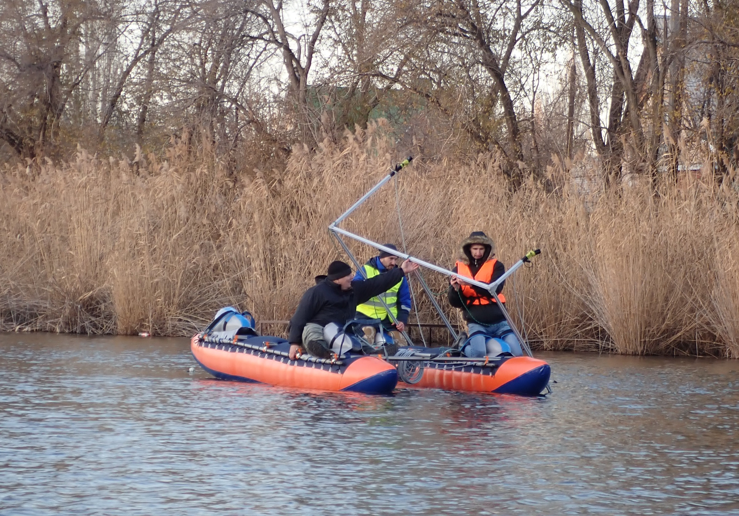
In fairness, it is worth saying that throughout the ideology of work, it should come down only once. We also had to raise it during testing - the profile costs money, and hydrophones do not lie on the road.
Summarizing the review of KB systems, we note that:
The advantages of KB systems include:
- speed of deployment and mobility (systems are usually mounted on a ship);
- on average, higher accuracy compared to UKB systems (although, however, it must be borne in mind that some high-class UKBs, for example [8] , generally show greater positioning accuracy than some simpler KBs like the already mentioned Waterlinked GPS [10] ) .
The cons of KB include the same disadvantages that are inherent in UCB systems, namely:
- the need to determine the orientation of the measuring base (baselines) - at the corners of the course, roll and trim in addition to being tied to the absolute geographical position;
- correlation of errors in determining arrival times on base elements in view of their kinematic connection, for example, due to pitching
- and, since a design bureau can generally work as a goniometric system, it is also subject to the problem of decreasing accuracy when moving a positioned object from the base.
- also can be attributed to the minuses and complexity (read the "price") of the initial installation of the system on the ship.
Long Base Systems
These are my favorite type of systems. DB - means Long base
DB systems provide maximum accuracy in determining the positioning of a positioned object
DB systems are much less susceptible to errors associated with multipath propagation, as will be shown below - if the direct beam is incorrectly determined, the travel time difference can be small (units of meters), which can be easily compensated by the presence of excess reference points, in the worst case only an error in determining the location of the order of the difference in the path of the beam, while the UCB could estimate the angle of arrival of this beam, which can turn out to be almost anything, which in turn leads to totally unacceptable error.
Of the minuses of DB systems, the main ones are the complexity of the installation, which is especially true in the case of the bottom base - firstly, bottom elements should provide sufficient autonomy to maximize the service time interval, and secondly, because as a rule such systems operate at considerable depths (from 500 meters and more), then additional requirements are imposed on normobaric buildings; thirdly, there is an additional problem of removing the base upon completion of work.
And finally, after installing the base, the location of its elements must be determined with geodetic accuracy, for example, using the virtual DB method or UCB systems using a large selection of measurements.
All these operations require specialized, expensive equipment and the labor of many highly qualified specialists.
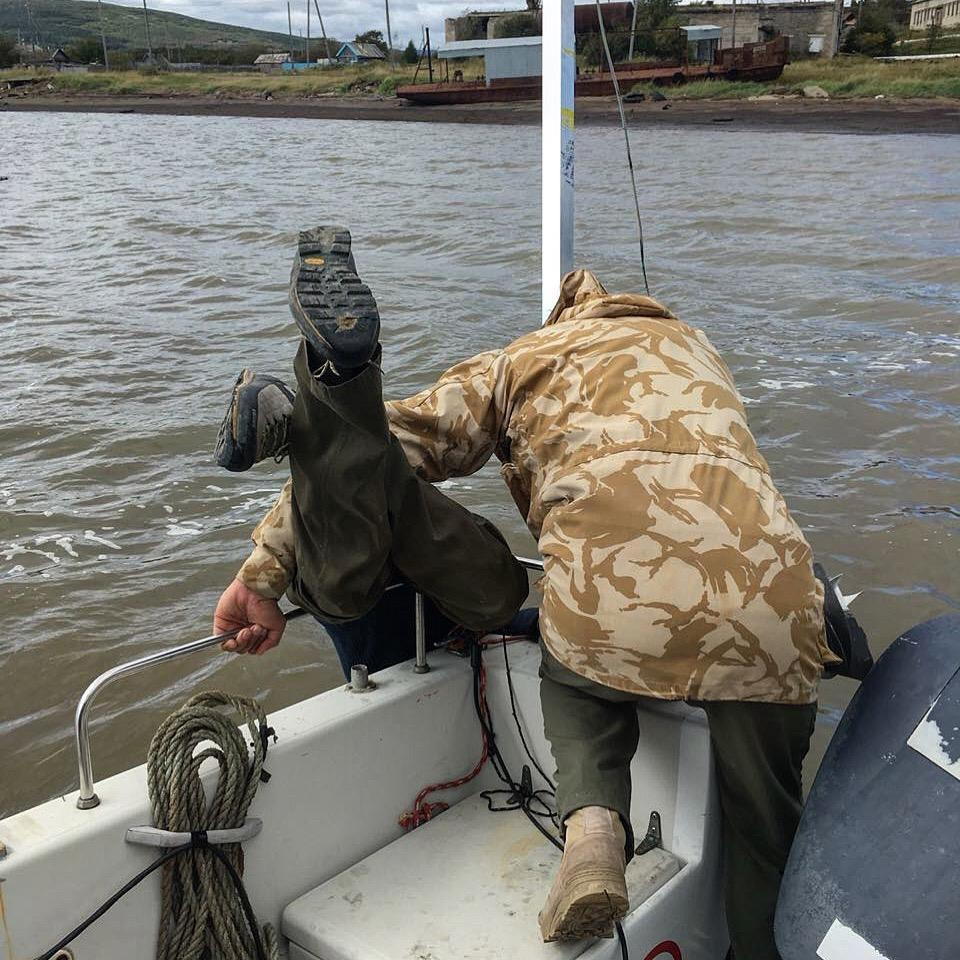
Much simpler is the case with the floating base. Hydroacoustic receiving, transmitting or receiving and transmitting buoys can be installed from almost any watercraft (we set our own in 15 minutes from a rowing inflatable boat), due to the ease of installation and removal, the supporting elements can have little autonomy, and their hulls can generally be made atmospheric performance.
It is worth saying that the use of a floating base is greatly complicated when working at great depths for two reasons: the first is the difficulty of installing an anchor, which in principle is solved by a motorized floating base, which ensures automatic preservation of the geographical position, and the second is more serious, and it often excludes the use of a floating base when working at great depths - the presence of complete internal reflection of the signal from the jump layer (meaning the layer of the jump in the speed of sound. The separation of water layers with different density, from which sound can be completely reflected).
The only solution here is to move the hydroacoustic antenna under the jump layer, which in turn creates even more problems - the complexity of the topographic location of the hydroacoustic antenna, the weight of the cable, a very complicated design, and here we are again where we started.
Traditionally, as a visual example, I bring our RedWAVE DB system, buoys (a diver is unique and is not included in the package):
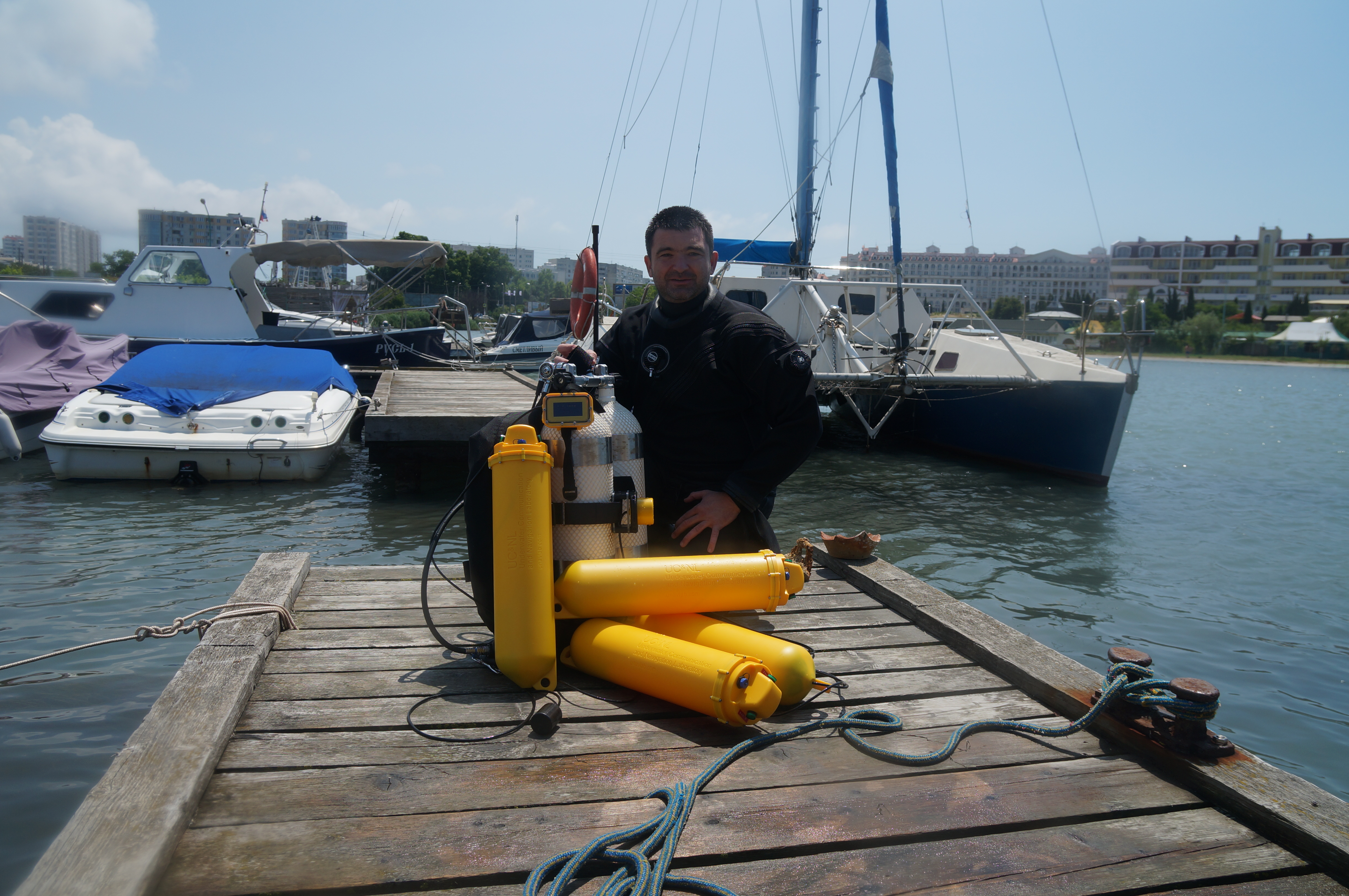
And the navigation receiver:

We have several articles about this system.
Virtual Long Base Systems
Systems based on the so-called virtual long base [22] [23] [24] (VDB, English VLBL - virtual long baseline) are worthy of a separate group for structural and layout reasons.
The essence of VDB systems is that the inclined ranges to the transponder or the pinger signal arrival times are measured at different points in space, this approach is true if one condition is met: the positioned object maintains a fixed position, and the moving reference point forms elements of the navigation base by making or measuring the distance to the defendant or fixing the arrival times of the pinger signal from different positions.
This class of navigation systems, with all its apparent limitations, has the broadest prospects: firstly, no complicated equipment is required, as for example with UHF systems - the task is solved nominally only with two transceivers or with a transmitter and receiver, which are not required by what or in a special way to orient in space. In the case of the pinger, it is possible to organize a cooperative search for the pinger using a flock of autonomous surface vehicles. This is especially true in the case of the search for sunken objects (for example, crashed planes or ships) on a theoretically unlimited area.Also, one of the methods for initially determining the location of the elements of the bottom long base is the WDB method.
As an example, I’ll give our demo project (even two!) Of a virtual long base on two uWAVE micro modems.
The first draft is described in one of our previous articles . There, the modem, GNSS module and radio module were combined using a board on the STM32.
In the new reincarnation of this project, the code was rewritten to Arduino UNO, and the navigation task is solved in an open source application .
Combined systems
Combined systems usually contain elements of two or more classes of systems. So, for example, there are technical solutions described in the review [1] combining a deployable long base and a short base mounted on a ship, the main task of which is to position the elements of a long base. Obviously, the positioning of the elements of a long base can also be carried out with the help of UKB systems.
In general, it can be stated that the choice of a particular synthesis scheme is determined, oddly enough, by the problem being solved.
In the vast majority of cases, the goal of the synthesis of different classes of systems is the initial positioning of the support points of a long base.
Exotic
Here we will only briefly touch on some classes of systems, as soon as indirectly and formally related to the topic of the article.
Among them, acoustic systems based on dead reckoning are built on the so-called Doppler logs, devices that measure the speed of a positioned object relative to the bottom by emitting an acoustic signal in at least three narrowly directed rays and their subsequent reception. Moving the object relative to the bottom leads to a Doppler frequency shift of the emitted signal detected at the receiving stage.
The Doppler shift is recalculated in the projection of velocity along three axes. In combination with the readings of the heading sensor (compass) and the readings of the accelerometer, a sequence of decisions is formed for the location of the object. Initiation of this sequence requires an initial positioning. This type of system has mainly military applications in view of relative secrecy and autonomy. It has all the drawbacks of dead-reckoning systems that are associated with the rapid accumulation of errors. Those.accuracy decreases over time.
Still there is exotic-exotic and quite exotic. To the first, I would refer systems based on the analysis of bottom images ( CARL! ), And to the second, navigation through magnetic field fluctuations ( CARL !!! ). Regarding the practical applicability of both of them, one wants, as they say, "to express serious concern."
In the dry residue
So, in the existing classification there are three main classes of sonar navigation systems:
- , - . , , , . [1] 0.5-0.2% .
- , ( ) , ; , -, , [1] , 0.5% ;
- , ( ), . , — , , [1] — 0.1% . , Vickery , — 2-3 ( 15 ), 1 (19-36 ) 5 , 50 110 .
PS
Thank you very much for your attention, we will be glad to listen to constructive criticism and answer questions.
If this article will cause interest among readers, then in the next I plan to talk about the correct classification of underwater navigation systems.
If all goes well, then in another article I will analyze several algorithms for the operation of navigation systems with code examples.
List of sources
- Vickery, K. (nd). Acoustic positioning systems. A practical overview of current systems. Proceedings of the 1998 Workshop on Autonomous Underwater Vehicles (Cat. No.98CH36290).
- Diogenes Laertius. The Lives and Opinions of Eminent Philosophers by Diogenes Laertius (Translation by Yonge, CD). London: George Bell and sons, 1905. Google books. Web. 01 Apr. 2019.
- Frankland, William B., The First Book of Euclid's Elements: With a Commentary Based Principally Upon that of Proclus Diadochus. Cambridge: at the University Press, 1905 .
- Accuracy Limitations of Hyperbolic Multilateration Systems, Harry B. Lee, Massachusetts Institute of Technology, Lincoln Laboratory, Technical Note 1973-11, March 22, 1973
- evologics.de/usbl
- www.tritech.co.uk/media/products/usbl-tracking-system-micronnav.pdf
- www.ixblue.com/products/posidonia
- www.ixblue.com/sites/default/files/2018-02/Gaps.pdf
- Integrating Precision Relative Positioning Into JASON/MEDEA ROV Operations, Bingham et al., MTS Journal Spring 2006 (Volume 40, Number 1)
- waterlinked.github.io/docs/explorer-kit/introduction
- www.ixblue.com/sites/default/files/2019-01/Ramses%20-%20Datasheet.pdf
- evologics.de/web/content/16763?unique=cc5bc295cb0a4bf681a31de24fdb204f62169c2b&download=true
- github.com/ucnl/Docs/blob/master/RU/RedWAVE/RedWAVE_LBL_Deployment_maintenance_RedNAV_ru.pdf
- www.alseamar-alcen.com/sites/alseamar-alcen.com/files/pdf/products/fiche_205x292_gib-sar.pdf
- www.gps.gov/technical/ps/2008-SPS-performance-standard.pdf
- «The Global Navigation System GLONASS: Development and Usage in the 21st Century». 34th Annual Precise Time and Time Interval (PTTI) Meeting. 2002.
- download.esa.int/docs/Galileo_IOV_Launch/Galileo_factsheet_2012.pdf (PDF). ESA. 15 February 2013. Retrieved 8 December 2019.
- «Directions 2017: BeiDou's road to global service». GPS World. 6 December 2016.
- Derek Howse, Radar At Sea. Macmillan Press, Great Britain 1993. ISBN 1-55750-704-X
- 54025-2010 «». . .
- The Development of Loran-C Navigation and Timing, Gifford Hefley, US National Bureau of Standards, Oct. 1972.
- MB Larsen, «Synthetic Long Baseline Navigation of Underwater Vehicles,» presented at Oceans 2000 MTS/IEEE Conference and Exhibition, 2000.
- JoÃo Saúde, Antonio Pedro Aguiar, Single Beacon Acoustic Navigation for an AUV in the presence of unknown ocean currents, IFAC Proceedings Volumes, Vol. 42, Issue 18, 2009, pp. 298-303, ISSN 1474-6670, ISBN 9783902661517, doi.org/10.3182/20090916-3-BR-3001.0057 .
- Alexander Dikarev, Stanislav Dmitriev, Vitaliy Kubkin, Andrey Vasilenko. Position estimation of autonomous underwater sensors using the virtual long baseline method, International Journal of Wireless & Mobile Networks (IJWMN), Vol. 11, Issue 2, April 2019