Introduction. Lyrics, you can skip
Hello again! In this story, I would like to continue the topic of home "robotics", this is a kind of continuation of the previous post .
I’ll immediately warn you: I’m not a specialist in this industry, I’m just learning and for a long time I’ve been “embarrassed” to express my thoughts and lay out home-made things here. I have been reading publications on Habr for a long time, sometimes you are amazed at what is happening in the world! You read a post, you don’t understand where the author knows from! How can you even figure this out! In the light of all this, I thought that my “clumsy” presentation would not be interesting to anyone, but more than 9k people watched the previous story, for me it is certainly a success, I think many people like me are “ordinary people” without diplomas from the Massachusetts Institute of Technology , so this info is more accessible to them. So let's go ...
Alteration of the structure
As the basis of my project, I took the previous "creation", a chupocabra, which was dressed up and under a light-sound performance, conducted a holiday. I did it for the sake of one day and from improvised means, which can be traced in its appearance, the performance was satirical. It looked something like this:
First of all, I removed everything unnecessary, bought aluminum profiles and perforated corners for a new design.
I really liked the performance of the telepresence robot from the foreign company "Origibot"
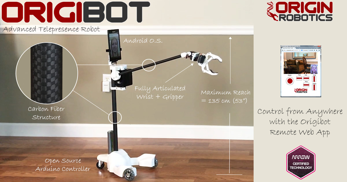

Its ascetic appearance has several advantages, judge for yourself, the weight is not large, this is primarily saving power, ergonomics, saving battery power, a less powerful electric drive. Imagine this situation, hypothetically, we went ahead and at that time communication problems, if the weight of the robot is several tens of kilograms, the consequences can be fatal. The second advantage of this form I consider the ability to fold the manipulator between the wheels, it is possible to lift something off the floor.
Oh well, inspired and go! Remaking “his”, he decided to divide the production in stages:
- The manufacture of the wheelbase based on two driving wheels and one supporting rear.
- Writing a sketch for management.
- Mounting a camera or phone. The height of placement was chosen based on the height of the stove in the kitchen, so that you could look into the pan and see what the soup was cooked from.
- Installing a servo on the camera so that you can look under the "legs" and the ceiling. I did not bother with horizontal movement, you can turn the base.
- Installation on the "product" of the manipulator with a grip.
Further commissioning, as regards the general concept of the robot, in the ideal case which has not yet been implemented, the main telecommunication device should be a telephone. Skype is installed on it, which is configured to receive video calls automatically, and the phone will also be an access point for a board based on the ESP module, this will make it possible to control the robot and video conferencing. Why skype Why come up with something if you already have services that work perfectly and change the quality automatically, depending on the network bandwidth.
There were no problems with the first item, the base was ready from the previous craft, removed everything superfluous, the TPlink MR3020 router with a home-made remote antenna. In the previous speech there were “thick” walls, I had to collective farm, the result is + 9db. Traffic control commands came to the router, cyberWRT firmware.
With the second point it was more interesting, my level in arduino programming “LED Blinker”, I found a ready sketch on the Internet, unfortunately I don’t remember the author, I didn’t alter it much for myself using the scientific poke method, it is used by those who poorly understand the theory. Since programming in even lower-level languages is a dark forest for me, I had to choose a platform on which I could build my own control panel. An important aspect for me was the ability to control the robot through a cloud service, since the control will be from the "gray addresses". The Blynk service has become such a platform, I will not describe the advantages, there is a lot of information on the network. In the first version, I used the joystick widget to control the movement, the code is shown below:
#define BLYNK_PRINT Serial #include <ESP8266_Lib.h> #include <BlynkSimpleShieldEsp8266.h> #include <AccelStepper.h> #include <Servo.h> #include <SimpleTimer.h> // You should get Auth Token in the Blynk App. // Go to the Project Settings (nut icon). char auth[] = "****"; // Your WiFi credentials. // Set password to "" for open networks. char ssid[] = "****"; char pass[] = "****"; #define EspSerial Serial3 #define ESP8266_BAUD 115200 ESP8266 wifi(&EspSerial); BlynkTimer timer; Servo servo; Servo servo2; // These are used to set the direction of the bridge driver. #define ENB 5 //ENB monstr motor shield 5 6 #define MOTORB_1 4 //IN3 #define MOTORB_2 9 //IN4 #define MOTORA_1 8 //IN1 #define MOTORA_2 7 //IN2 #define ENA 6 //ENA int motor_right_speed = 0; int motor_left_speed = 0; AccelStepper Stepper1(4, 10, 11, 12, 13); //4 , int steeps = 192; // , , // SETUP void setup() { Serial.begin(9600); delay(10); EspSerial.begin(ESP8266_BAUD); delay(10); // Connect Blynk Blynk.begin(auth, wifi, ssid, pass); Blynk.connect(); // Configure pins pinMode(ENA, OUTPUT); pinMode(MOTORA_1, OUTPUT); pinMode(MOTORA_2, OUTPUT); pinMode(ENB, OUTPUT); pinMode(MOTORB_1, OUTPUT); pinMode(MOTORB_2, OUTPUT); digitalWrite(ENA,LOW); digitalWrite(ENB,LOW); Stepper1.setMaxSpeed(10000); // (/) Stepper1.setAcceleration(10000); // (/^2) servo.attach(1); servo2.attach(3); servo2.write(55); timer.setInterval(500L, StopServo); // Start serial communication } BLYNK_WRITE(V1) / , , / { if (param.asInt() == 1) { servo.attach(1); servo.write(165); // High gear timer.setTimeout(500L, StopServo); } else { servo.attach(1); servo.write(115); // Low gear timer.setTimeout(500L, StopServo); } } BLYNK_WRITE(V2) { servo2.write(param.asInt()); } void StopServo() / { servo.detach(); } // JOYSTICK BLYNK_WRITE(V0) { int nJoyY = param[0].asInt(); // read x-joystick int nJoyX = param[1].asInt(); // read y-joystick // OUTPUTS int nMotMixL; // Motor (left) mixed output int nMotMixR; // Motor (right) mixed output // CONFIG // - fPivYLimt : The threshold at which the pivot action starts // This threshold is measured in units on the Y-axis // away from the X-axis (Y=0). A greater value will assign // more of the joystick's range to pivot actions. // Allowable range: (0..+127) float fPivYLimit = 1023.0; // TEMP VARIABLES float nMotPremixL; // Motor (left) premixed output float nMotPremixR; // Motor (right) premixed output int nPivSpeed; // Pivot Speed float fPivScale; // Balance scale between drive and pivot // Calculate Drive Turn output due to Joystick X input if (nJoyY >= 0) { // Forward nMotPremixL = (nJoyX>=0)? 1023.0 : (1023.0 + nJoyX); nMotPremixR = (nJoyX>=0)? (1023.0 - nJoyX) : 1023.0; } else { // Reverse nMotPremixL = (nJoyX>=0)? (1023.0 - nJoyX) : 1023.0; nMotPremixR = (nJoyX>=0)? 1023.0 : (1023.0 + nJoyX); } // Scale Drive output due to Joystick Y input (throttle) nMotPremixL = nMotPremixL * nJoyY/900.0; // nMotPremixR = nMotPremixR * nJoyY/1023.0; // Now calculate pivot amount // - Strength of pivot (nPivSpeed) based on Joystick X input // - Blending of pivot vs drive (fPivScale) based on Joystick Y input nPivSpeed = nJoyX; fPivScale = (abs(nJoyY)>fPivYLimit)? 0.0 : (1.0 - abs(nJoyY)/fPivYLimit); // Calculate final mix of Drive and Pivot nMotMixL = (1.0-fPivScale)*nMotPremixL + fPivScale*( nPivSpeed); nMotMixR = (1.0-fPivScale)*nMotPremixR + fPivScale*(-nPivSpeed)/ 1.1; motor_left_speed = nMotMixL; motor_right_speed = nMotMixR; if (motor_right_speed > 20) { digitalWrite(MOTORA_1,HIGH); digitalWrite(MOTORA_2,LOW); } else if (motor_right_speed < -20) { digitalWrite(MOTORA_1,LOW); digitalWrite(MOTORA_2, HIGH); } else { digitalWrite(MOTORA_1, LOW); digitalWrite(MOTORA_2, LOW); } if (motor_left_speed > 20) { digitalWrite(MOTORB_1, LOW); digitalWrite(MOTORB_2, HIGH); } else if (motor_left_speed < -20) { digitalWrite(MOTORB_1,HIGH); digitalWrite(MOTORB_2,LOW); } else { digitalWrite(MOTORB_1, LOW); digitalWrite(MOTORB_2, LOW); } analogWrite(ENB, abs(motor_left_speed)); analogWrite(ENA, abs(motor_right_speed)); } BLYNK_WRITE(V3) { // Motor Speed - Slider set with 0-100 and Send On Relese OFF int pinValue = param.asInt(); Stepper1.move(pinValue); } // MAIN CODE void loop() { Blynk.run(); timer.run(); Stepper1.run(); }
Next, the installation of the camera or phone, I tried both.
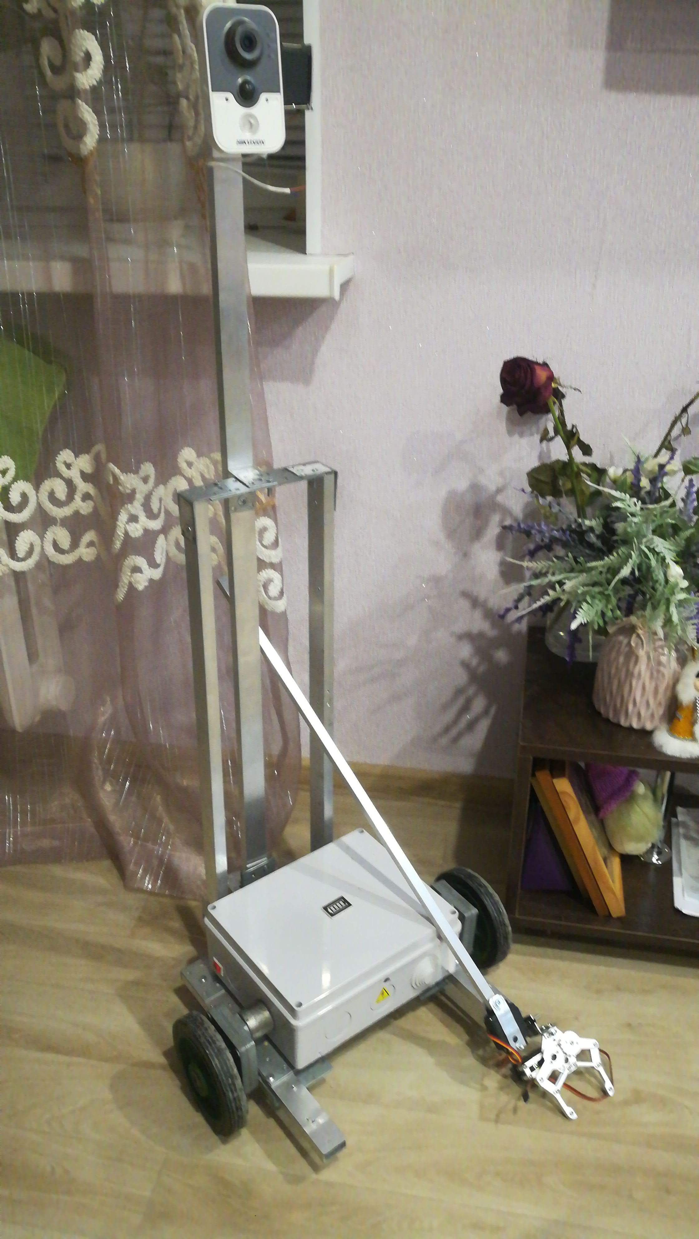
In the photo, the manipulator stands separately.
Now it's time for the test! I took the opportunity to split the screen on the phone (available in the latest android firmware), the upper part of the video, bottom control. To start everything at the same time I downloaded the Screens application from the Play Market and went ...
During the first “pokatushek” the following shortcomings were revealed, the engines which in their German past, used to spin something on some attraction, have different outputs as a result of a straight line, movement does not work. All the time it pulls in one of the sides, made an adjustment to calculating the speed of the engines in the code, it helped, but decided to remake the code into buttons, it’s more convenient for me, and the movements in the apartment will be mostly linear.
This was followed by the most time-consuming stage as it turned out, now it is clear why many telepresence robots on the market do not have a manipulator. Not so long ago, delving into the study of the issue, I read about methods for calculating drives for rotation that are not evenly distributed along the load axis, I remembered how I sat at the institute at a lecture on theoretical mechanics fifteen years ago and picked my nose thinking: “Why do I need a future #Engineer - an electrician # this crap. " Well, okay, as they say: "Practice without theory is blind." About ten times I redid the manipulator, burned several servos, which were supposed to lift the main load.
If you paid attention to the Origibot photo, there is something terrible there as a drive, on their website I read that the manipulator is capable of lifting up to 1 kg, fantastic!
If we apply for example a servo drive with a force of 20 kg / cm, then at a distance of 2 cm you can lift a load of 10 kg, and if the weight of this load is unevenly distributed along the axis and the axis is about a meter, then even less.
It’s good that the old rotary CCTV camera was at hand, I extracted two stepper motors from it, great! One engine will raise the axis, and the second I use on an automatic curtain. I have long wanted to make a home, but at the same time figure out how to work with stepworms! So to speak, two birds with one stone, at once. Yeah! The main "trouble" was waiting ahead, I forgot to say that I used the Wemos D1 R1 controller for my homemade product, it looks similar to Arduino Uno, only there is wifi on board. While there was no manipulator, there were enough pins on the board, a stepper motor added, to control the windings you need four pins, where can I get it? It turned out that the pins of the board are the pins of the CES itself, which provides communication, the pins from the 0th to the 8th are repeated further. Well, as they say: "A bad head gives no peace to your hands!"
The price of the error - transferring the results of work to the Wemos 2560 esp8266 board, this board is the usual Mega and Esp. I took it for automation of the greenhouse, of course it didn’t go right away, the sketch did not compile, errors flew out. Found a solution on the site:
community.alexgyver.ru/threads/robotdyn-mega-wifi-r3-connect-blynk.1270/#post-16746
Below is a sketch for a button-controlled Mega:
#define BLYNK_PRINT Serial #include <ESP8266_Lib.h> #include <BlynkSimpleShieldEsp8266.h> #include <AccelStepper.h> #include <Servo.h> #include <SimpleTimer.h> #define EspSerial Serial3 #define ESP8266_BAUD 115200 ESP8266 wifi(&EspSerial); #define ENB 5 //ENB monstr motor shield 5 6 #define MOTORB_1 4 //IN3 #define MOTORB_2 9 //IN4 #define MOTORA_1 8 //IN1 #define MOTORA_2 7 //IN2 #define ENA 6 //ENA BlynkTimer timer; Servo servo; Servo servo2; AccelStepper Stepper1(4, 10, 11, 12, 13); //4 , char auth[] = "****"; char ssid[] = "****"; char pass[] = "****"; // SETUP void setup() { Serial.begin(9600); delay(10); EspSerial.begin(ESP8266_BAUD); delay(10); // Connect Blynk Blynk.begin(auth, wifi, ssid, pass); Blynk.connect(); // Configure pins pinMode(ENA, OUTPUT); pinMode(MOTORA_1, OUTPUT); pinMode(MOTORA_2, OUTPUT); pinMode(ENB, OUTPUT); pinMode(MOTORB_1, OUTPUT); pinMode(MOTORB_2, OUTPUT); Stepper1.setMaxSpeed(100); // (/) Stepper1.setAcceleration(96); // (/^2) servo.attach(2); // servo.write(115); // servo2.attach(3); // servo2.write(55); // //timer.setInterval(500L, StopServo); // Start serial communication } BLYNK_WRITE(V6) { servo.write(param.asInt()); //timer.setTimeout(2500L, StopServo); } BLYNK_WRITE(V7) { servo2.write(param.asInt()); } //void StopServo() { // servo.detach(); //} BLYNK_WRITE(V8) { int pinValue = param.asInt(); Stepper1.move(pinValue); } BLYNK_WRITE(V4) { int speedL = param.asInt(); // . 1,13 analogWrite(ENA, speedL); analogWrite(ENB, speedL* 1.13); } / FORWARD BLYNK_WRITE(V0) { int button = param.asInt(); // read button if (button == 1) { digitalWrite(MOTORA_1,HIGH); digitalWrite(MOTORA_2,LOW); digitalWrite(MOTORB_1,HIGH); digitalWrite(MOTORB_2,LOW); } else { digitalWrite(MOTORA_1,LOW); digitalWrite(MOTORA_2,LOW); digitalWrite(MOTORB_1,LOW); digitalWrite(MOTORB_2,LOW); } } // RIGHT BLYNK_WRITE(V1) { int button = param.asInt(); // read button if (button == 1) { digitalWrite(MOTORA_1,LOW); digitalWrite(MOTORA_2,HIGH); digitalWrite(MOTORB_1,HIGH); digitalWrite(MOTORB_2,LOW); } else { digitalWrite(MOTORA_1,LOW); digitalWrite(MOTORA_2,LOW); digitalWrite(MOTORB_1,LOW); digitalWrite(MOTORB_2,LOW); } } // LEFT BLYNK_WRITE(V2) { int button = param.asInt(); // read button if (button == 1) { digitalWrite(MOTORA_1,HIGH); digitalWrite(MOTORA_2,LOW); digitalWrite(MOTORB_1,LOW); digitalWrite(MOTORB_2,HIGH); } else { digitalWrite(MOTORA_1,LOW); digitalWrite(MOTORA_2,LOW); digitalWrite(MOTORB_1,LOW); digitalWrite(MOTORB_2,LOW); } } // BACKWARD BLYNK_WRITE(V3) { int button = param.asInt(); // read button if (button == 1) { digitalWrite(MOTORA_1,LOW); digitalWrite(MOTORA_2,HIGH); digitalWrite(MOTORB_1,LOW); digitalWrite(MOTORB_2,HIGH); } else { digitalWrite(MOTORA_1,LOW); digitalWrite(MOTORA_2,LOW); digitalWrite(MOTORB_1,LOW); digitalWrite(MOTORB_2,LOW); } } // MAIN CODE void loop() { Blynk.run(); timer.run(); Stepper1.run();
As a result, the power of the Chinese noun was even less - 5kg / cm, I decided to try through the belt:
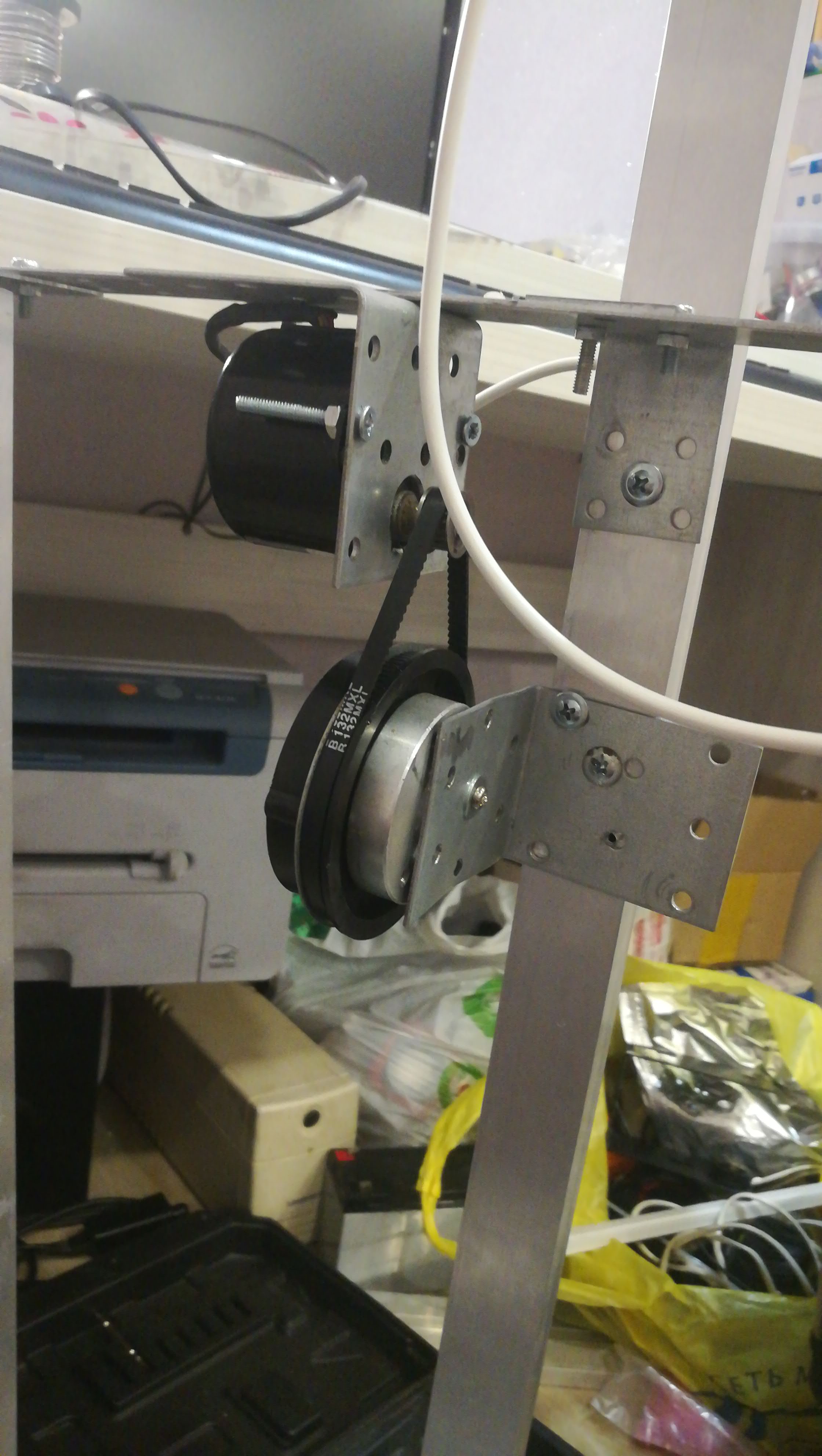
The belt slipped despite the tensioner attached to the roller (Not pictured). Exceptional psychosis and nervousness caused by a series of technical setbacks were interrupted by a new idea. It is necessary to reduce the weight of the structure - to abandon the two servos at the end of the axis, for additional degrees of freedom and reduce the length of the axis of the manipulator. (I hope the fuse will remain and this decision is temporary).

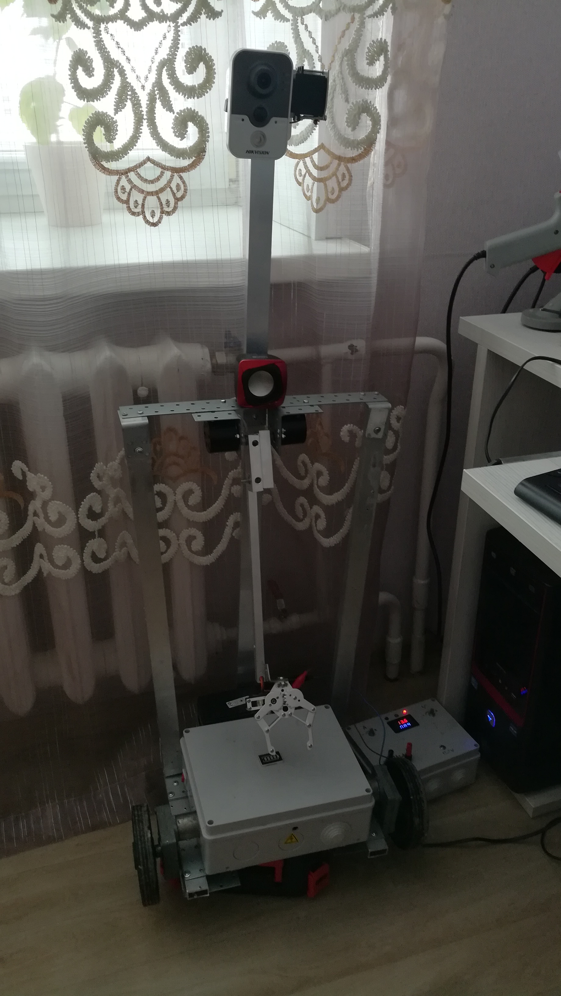
Also on the photo, I installed an external speaker, which was soldered to the ds-2cd2432f-iw camera by the manufacturer Hikvizhn. The full-time speaker seemed weak.
Now the appearance is as follows.
Summary
We have a camera on wheels, so far I have refused the phone. Skype does not work correctly in the multi-window mode on my phone, when controlling the video image is minimized to the size of a small window, which is not very convenient when the robot moves. Therefore, I stopped while on the camera, I still use the paid version of the Tiny cam pro program to access the video, access from anywhere in the world, the camera is connected wirelessly to a router on which its ports are forwarded and the No-Ip domain name service is used. It's good that the provider so far provides a "white" address. Why I do not use Blynk for video transmission, you ask, because there is a standard widget for transmitting the rtsp protocol. I answer, I want to use the entire functionality of the camera, namely two-way communication. Even if it is in such a form as it is provided by an application in which audio codecs are used that greatly reduce the sound quality. The most important rtsp protocol in the Blynk application works with a slight delay, which is critical for traveling on a mechanism that weighs 10 kg.
Nutrition, a separate interesting topic. The issue of an autonomous charging station has not yet been resolved, did not have time. On the previous model, I used Li-ion batteries soldered in pairs in parallel, to increase the voltage to 12V and increase the capacity, working through the charge controller. In this project, he refused lithium, the batteries explode terribly from a bad experience! A lead-acid battery 7A / h is installed in the rear of the unit, for uniform load distribution when the load is lifted by the manipulator. A dc converter that reduces the voltage of 5V is connected to the battery to power the controller and the logic of two MonstrmotorShield engine drivers, one for each wheel, because only the driver’s floor worked in both boards, most likely a factory defect, couldn’t give a mind, well, can’t I throw it away? .. The ln298 motor driver is needed for two stepper motors to work.
Of the problems not yet resolved, autonomous charging, I want to repeat it like this
I also did not quite understand the AccelStepper library, if you supply power to the motor windings, after the manipulator is finished, the power remains, which increases the battery discharge current by about 400mA, which is not economical, you need to come up with the logic when the manipulator is in the lower position, the windings power is turned off. I would also like feedback so that the position of the servos and stepworms comes to Blynk when the robot is turned on. And of course, the battery must disconnect the load when the voltage drops to 10.5V, which will prevent its premature degradation. There is no way to control from a computer. And of course, the code needs optimization.
Those who are not afraid of many books and read to the end, thank you, good luck to everyone, all good!
In the end, we’ll be a little dirty!