What is this article about
This article describes the principles of building the simplest transformerless power sources. The topic is not new, but, as experience has shown, is not well-known and understandable to everyone. And even some interesting.
I ask those who are interested and interested to read, criticize, clarify and add to shiotiny@yandex.ru or to my site in the "Contacts" section.
Introduction
Not so long ago, a friend of mine got his fingers into a certain scheme that he was going to fix (the wires fell off - so you just had to solder it in place). And he was shocked. It didn’t hit hard, but it was enough for him to be surprised: “how so - here the microcontroller stands, what can knock here? It is powered by 5 volts! ”
His surprise was quickly clarified: the circuit turned out to have transformerless power and without galvanic isolation from the network.
Then questions followed in my direction. They were reduced to two things: “What? So you can do it ?! "and" And how does it work? "
Although I do not consider myself an expert in electronics, I had to do such power supplies. So I had to take a pen and a piece of paper and explain how it works. Fortunately, this is not at all difficult.
It is possible that the theme of “transformerless” power supplies or, in short, BIP , may seem interesting to you. Someone for the general development, and someone for practical use.
Home AC Power Supplies
I warn you right away: I will deliberately not touch on switching power supplies here. This is a topic for another conversation.
Generally speaking, the functions of a power source for low-voltage electronic equipment usually consist of the following: provide a given voltage at the output of a power source for a given range of current consumption. That is, to put it formally, the power source is a constant voltage source Uout , which saves Uout = const when the current consumption changes from Imin to Imax .
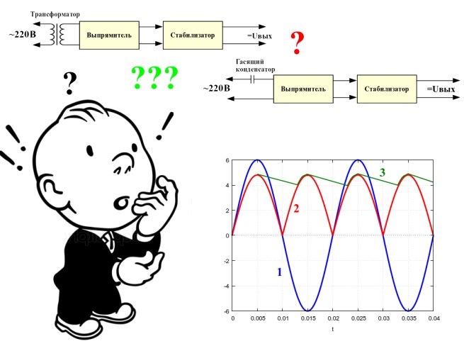
In a “classic” linear power supply, this usually happens like this: the input mains voltage is reduced by a transformer, then this voltage is rectified and finally stabilized by a linear stabilizer.
The block diagram of the “classic” linear power supply is shown in the figure below. One of the most "inconvenient" parts of such a power source is a transformer: it is expensive and bulky.

Therefore, radio amateurs and radio professionals were looking for ways - how to abandon this bulky and expensive part - a transformer, or at least reduce its size and cost.
And such a solution was found: they began to use the reactance of the capacitor Rc in order to “extinguish” the excess voltage. The block diagram of the “transformerless” power supply ( BIP ) is shown below.

As you can see, the structure of the BIP is almost no different from the classic linear power source. Is that instead of a transformer put a quenching capacitor. Do not be confused or deceived by the similarity of the structure of these power sources in the figure: there are a lot of differences inside .
Advantages of the BIP : it is relatively compact, reliable, cheap, not afraid of a short circuit in the output.
But there are significant drawbacks: it is dangerous from the point of view of a person touching the elements of a powered device. And the maximum current that such a power source can provide is only a few hundred milliamps. With a larger current, the dimensions of the capacitors are large and it is easier to install a transformer or even to install a pulse generator.
Based on the advantages and disadvantages of the BIP , its scope is well-insulated low-power devices powered by a household electrical network: stand-alone sensors, lighting control devices, ventilation and heating switching devices, and other low-power devices that work autonomously.
Let's try to understand how the real BIP circuit works and how to calculate it.
Practice theory and practice theory
An example of a simple practical scheme
Since before, before the advent of cheap “impulses”, BIPs were probably the most affordable way to reduce the size and price of a power source, then BIP circuits in books and the Internet are a carriage and a small cart. But the principle of operation of almost all circuits is approximately the same: one or more quenching capacitors at the input, a rectifier and an output DC voltage stabilizer.
Let's look at one of the simplest working circuits of the BIP , which is shown in the figure below.

All the main parts of the circuit are immediately visible: a quenching capacitor C1 ; a half-wave rectifier - a diode bridge VD1 and a smoothing capacitor C2 ; voltage stabilizer - zener diode VS1 ; and finally, the load is a Rn device powered by the source.
Forget about the "extra elements" or "the basic formula of the BIP"
For simplicity, let us forget about the existence of resistors R1 and R2 : we assume that R2 is absent at all, and R1 is replaced by a jumper. For all calculations, this is not essential, but we will talk about the purpose of these resistors later. That is, temporarily, the scheme for us will look like the following figure.

The alternating current of the power supply network, limited by the quenching capacitor C1 , flows through points 1 and 2 of the diode bridge VD1 .
The direct current obtained after rectification of the alternating diode bridge VD1 flows through the zener diode and the “load” Rn is the supplied device.
The diagram shows how all currents flow: Ic is the alternating current of the network, In is the direct current of the load, and Ist is the constant current of the zener diode.
Although I wrote “constant” and “alternating” currents - in fact it is one and the same current. Just a diode bridge makes it flow through the zener diode and the load is always in the same direction.
If we assume that we are measuring the effective value of the current , then we can write the basic formula for the operation of our BIP scheme:
This follows from the first law of Kirchhoff , which states that the sum of the currents flowing into any node is equal to the sum of the currents flowing from it and, in fact, is a particular formulation of the law of conservation of mass / energy.
From this formula, a simple but important conclusion follows: at a constant voltage , current consumed from the mains practically does not change when the resistance R changes in the current range - this is the key difference between the BIP and the linear power supply with a transformer.
Despite the fact that the block diagrams of the power supplies given at the beginning of the article are very similar, they work very differently: the step-down transformer in the first block diagram is a voltage source , and the quenching capacitor in the second block diagram is a current source !But back to our scheme. From the last formula it also becomes clear that the stabilizer circuit is essentially a current divider between the load R and the zener diode VS1 .
If the load R is completely torn off, then all the current will flow through the zener diode. If the load R is short-circuited, all current will flow through the load, bypassing the zener diode.
But to "tear off" the Zener diode VS1 from the circuit in no case! If you tear it off, then all the mains voltage can be supplied to the load R . The consequences will most likely be sad.
When pedantry is not needed
In any case, from the complete disconnection of R to its “short-circuit”, the current Ic flowing through the quenching capacitor C1 will be approximately equal ; Where - network voltage, and - the resistance of the capacitor C1 .
Pedants and other lovers of accuracy can blame me, they say I did not take into account the voltage on the diode bridge (between points 1 and 2 ). Therefore, the voltage across capacitor C1 will be slightly less than - voltage at the outlet.
Of course, strictly formally, fellow pedants will be right. But I dare to note that if the load we have is a low-power device with a power supply of 5V or 12V , and the voltage "in the socket" is about 220V , then the voltage drop across the load can be safely neglected: the difference in the "exact" and "approximate" calculations will be no more than a few percent.
What is the quenching capacitor resistance ? This is the reactance of the capacitor: it depends on the frequency of the voltage supplied to the capacitor and is calculated by the formula: , where f is the voltage frequency in Hertz and C is the capacitance of the capacitor in Farads. Since the network frequency is fixed at 50 Hz , for engineering calculations, you can use the formula: from where . For pedants, again, I remind you that the capacitance of the capacitor always has an error of a few percent (usually 5% -15% ), so it makes no sense to count more precisely.
Based on the above formulas, we can calculate the capacitance of the capacitor C1: . We know the mains voltage. A current can be calculated by knowing the maximum load current and the minimum stabilization current of the Zener diode VS1 (this is a reference parameter).
This is a theory. I’ll try to describe something like the methodology for calculating the BIP “on the fingers”.
Do we need a BIP at all?
To begin with, we will solve the question - is it even necessary to use BIP in a particular case?
If the load current Rn is greater than 0.3-0.5A , then it is better not to use the BIP : there is a lot of trouble , and usually there is little or no gain in size and cost. Also, usually you should not rely on a BIP if the supply voltage of the device is more than 24-27V . And do not forget about security!
Suppose that we need to power a simple circuit on a microcontroller that eats a moderate current of milliamps that way 100 at a moderate voltage of 3-6V. The circuit is isolated and therefore safe.
How to estimate the capacity of C1 and choose a zener diode VS1?
First of all, it is necessary to clarify the maximum load current Imax : calculate or measure.
Then, you need to get into the directory and find the zener diode there. Yes, not anyhow, but to the desired voltage Uout .
When searching for a zener diode, it should be borne in mind that its maximum stabilization current I max must be no less than (I min + In max) . Why is that? Yes, so that if you tear off the load Rn , the zener diode will not burn out. And vice versa - if the load consumes the maximum current, then the minimum stabilization current Imin passes through the zener diode. In practice, it is necessary to choose a zener diode so that its maximum stabilization current I max is greater than the sum of the currents (I min + Im max) by at least 20% . Do not forget that the network is far from always 220V . Maybe 250V easily. Therefore, the current margin is not an excess, but a reasonable precaution.
Next, we calculate the capacity of the quenching capacitor C1 . Its reactance will be approximately equal to: , and its capacity, respectively, is for mains voltage with a frequency of 50Hz .
Do not forget that the maximum permissible voltage of the capacitor C1 must be at least 400V for a household network of 220V . And, of course, the capacitor C1 should not be electrolytic: it works in an alternating current network.
Actually, this is the most important thing - selecting a zener diode and calculating the capacitance of a capacitor.
For those who are not clear what Istmax and Istmin are , I will explain in more detail.
The maximum stabilization current of the zener diode Imax is such a current through the zener diode, when it is exceeded, the zener diode fails.
The minimum stabilization current of the zener diode Imin is the minimum current through the zener diode at which the voltage on the zener diode corresponds to the rating characteristics.
That is, the zener diode should work in such conditions that the stabilization current Ist flowing through it lies in the range .
The values of Imin and I max for a particular zener diode can be found in the manual and they are always indicated in the description of the zener diode.
So, once again, on points, on how to calculate C1 and choose a zener diode VS1 .
- We determine the load voltage Uout . As a rule, we know it.
- We determine the maximum load current Imax . You can measure or calculate.
- We climb into the directory and look for a zener diode for a voltage Uout , such that the condition . (0.8 - because we want 20% current margin).
- We calculate the capacity of the quenching capacitor C1 according to the formula
Calculation example
Suppose that the load supply voltage is Uout = 5V and the maximum load current is Inmax = 100mA .
We climb into the directory and find there such a zener diode: KS447A . The stabilization voltage is about 5V . Istmin = 3mA , Istmax = 160mA .
We check. Inequality - is fulfilled, then the zener diode is suitable for current.
We calculate the capacitor C1 : . Do not forget that for a household 220V network, capacitor C1 must be 400V .
Filter or capacitor C2
The diode bridge, as you know, does not give a rectified voltage: the output voltage is pulsating.
To smooth the ripple, a filter capacitor C2 is used . How to calculate its capacity?
As usual, you can apply two methods - the exact and the simplified. The exact method takes into account that the capacitor is discharged exponentially and other nuances. But remembering that it is impossible to select the capacitors exactly for the required capacity (a capacity spread of 10-15% is the norm), we will allow some simplifications that will practically not affect the result.
To understand how to calculate the capacitance of a capacitor C2 , we recall what a rectifier is. Let's look at the picture below. The diagrams of voltage versus time look something like this in our circuit, using a diode bridge as a rectifier.
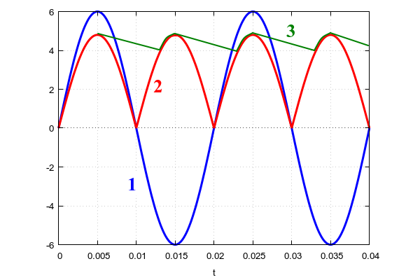
The blue line indicated by the number 1 is the alternating voltage at the input of the diode bridge (points 1 and 2 on the BIP circuit).
The red line, indicated by the number 2 , is the voltage at the zener diode VS1 , in the absence of a smoothing capacitor C2 or a ripple voltage (imagine that C2 was temporarily “bit off” from the circuit). And finally, the green line indicated by the number 3 is the smoothed rectified voltage when the capacitor C2 is connected.
The unfiltered (pulsating) voltage at the rectifier output (line 2 ) is slightly less in amplitude than the voltage at the rectifier input (line 1 ). This is explained simply: several tenths of a volt drops on the diodes.
Green line 3 shows the process of charging and discharging capacitor C2 . The maximum voltage that is able to charge in our circuit is the voltage at the zener diode VS1 . Then the capacitor starts to discharge until in the next period it starts to charge again.
The ripple amplitude is the voltage at which the capacitor C2 has been discharged in one period of the ripple voltage at the output of the rectifier (line 2 ).
It is not difficult to calculate the approximation of the ripple amplitude if we take the discharge current as a constant - this will be the maximum load current Rn , which we designated Imax .
According to the basic formula of the capacitor it can be roughly estimated that: where Is the ripple amplitude, a - time period one period of the ripple voltage at the output of the rectifier (line 2 ).
The figure clearly shows that the period equal to half the period of the supply voltage, or where f is the frequency of the mains voltage ( 50Hz ).
Thus, substituting one formula in another, we get: or .
Now the most difficult thing is to choose, but what is the amplitude of the pulsations that suits us? If the load has its own linear stabilizer, then in principle it is enough that the ripple amplitude is at the level of 10-20% . For example, often in the load Rn there is some kind of stabilizer - 7805 or AMS1117 or something else like that.
If it is supposed to power the digital circuit directly from our BIP without additional stabilization, then it is better not to set the ripple coefficient of more than 5% .
Suppose that our circuit is powered by 5V and has a maximum current consumption of 100mA . The ripple factor is set to 5% . It means that will be equal to 5% of 5V or 0.25V . Network frequency - 50Hz .
From here we find the capacitor C2 - . Nekhilaya such a capacity! Moreover, the closest large capacity is 4700uF . This is a fairly large capacitor even for a voltage of 10V .
If the circuit has a linear stabilizer inside, for example AMS1117 , then the ripple level can be selected at 20% , while the capacitance of the capacitor C2 will be only about 1000 μF .
Resistors R1 and R2 - necessary and important
Let's go back to the resistors R1 and R2 , which we temporarily forgot about.
With R2 resistor, everything is simple - it is needed for human safety. That is, in order for the capacitor C1 to discharge after disconnecting the circuit from the power supply. Otherwise, if R2 is not set, then the capacitor C1 will retain its charge for a rather long time after disconnecting the power from the circuit. And if you touch it, then you will be shocked. Very unpleasant. Resistor R2 can not be calculated, but simply put any resistance of 0.5 - 1 MΩ . With this resistance, the current through this resistor will be scanty and will not affect the operation of the circuit.
With the resistor R1, everything is more complicated. In the process of the BIP, it seems to be not needed. And indeed it is.
But there is still the moment of inclusion of the BIP in the network. And if at this moment the mains voltage is close to the amplitude value, then the circuit may burn out. Even almost certainly burn.
The fact is that at the moment of switching on, capacitor C1 is discharged. A discharged capacitor for a while (until it is sufficiently charged) is essentially a conductor. That is, all the mains voltage will be on the diode bridge, the load, the zener diode and the currents will be simply huge.
Therefore, they put a resistor R1 , the function of which is to limit the current at the time of switching on. For example, if you put R1 with a resistance of only 10 ohms , the turn-on current will be limited in the worst case to about 30A . And such a current for several microseconds is already quite within the power to withstand most zener diodes, not to mention rectifier diodes of the diode bridge.
Typically, this resistor is chosen in the range of 10-30 ohms . Just keep in mind that its power should be no less than . For example, if the total current consumption of the circuit is 150 mA , then the power of the resistor R1 with a resistance of 27 Ohms should be at least .
It is recommended to put the resistor R1 not “back to back” in power, but with a margin. For example, in our case it is 1.5 - 2W . It will be less heated.
In addition, note that the resistors R1 and R2 must be designed for a peak voltage of at least 400V: the mains voltage at the time of switching on is fully supplied to R1 , in operating mode, almost all the mains voltage is supplied to R2 , connected in parallel to capacitor C1 .
Conclusion
I hope that after reading, readers have an understanding of what a BIP is and how it works.
The article turned out to be somewhat longer than what I would like. But in fact, only the basics from the basics are considered here.If you paint further modifications of the BIP , then a brochure or even a book will come out.
I apologize for some inaccuracies and simplifications that will undoubtedly catch the eye of experienced electronic engineers.
Those who see errors or something that should be corrected and supplemented within reasonable limits - please do not hesitate to write in the comments, by mail to shiotiny@yandex.ru or to my
site in the "Contacts" section.
Thanks in advance for your feedback.