
SONY, having decided to show itself in the market of action cameras, releases a line of HDR devices. By beckoning customers with an attractive filling - a good matrix, fast processor, Zeiss optics and an electronic image stabilizer with low weight, the company shows its "true face of capitalism".
To control the camera, a remote control with video viewing over WiFi is released. The remote control is quite expensive and in short supply - now it can only be bought at various electronic flea markets.

But there is WiFi, so you can control it from your phone? Have you tried skiing or wakeboarding with a smartphone in your hands? But this inconvenience is still not enough:
SONY, completely not caring for its customers, removes the PlayMemories Mobile application from Google Play to control its action cameras via WiFi from any mobile phone, replacing it with a smartwatch application. Instead, it launches Imaging Edge Mobile - terribly uncomfortable and constantly falling off the camera. The same song for iPhone apps.
As a
The SDK is written to develop SONY camera control applications over WiFi from Android and iOS devices.
Inside the archive there are two directories with examples for developing Java applications for Android and iOS. The most interesting is the PDF document API references for Camera Remote API beta . It is decided - I will do the remote control with my own hands
What is in your API?
Firstly, there is a table of supported devices for February 2017.
Based on the table, the API with varying degrees of functionality is compatible with almost all HDR action cameras from AS15 to AS300, FDR cameras, DSC, ILCE and NEX series cameras with WiFi interface.
Next, I will describe how to work with the HDR AS100 camera with the latest firmware 2.0.0, implying that there must be compatibility with other devices.
Secondly, the camera control protocol. Each SONY device from this list is an HTTP server that executes requests, and also produces separate frames in JPEG format and streaming video.
My goal is to develop a compact and the cheapest remote control for SONY cameras
To get started, you need to make sure WiFi is turned on in the camera menu:
[SETUP] -> [CONFG] -> [Wi-Fi] -> [ON]
The identifier and password must be on a separate sticker in the operating instructions for the camera. If this sticker is lost, you can connect the camera via MicoUSB to a computer running Microsoft Windows and turn it on. [USB] will appear on the screen, and two network drives on the computer - with a memory card inserted in the camera and the internal memory of the PMHOME camera. We are interested in the second disc
The file: \\ INFO \ WIFI_INF.TXT contains the identifier and password for accessing the camera via WiFi, and the file \\ INFO \ WPS_PIN.TXT contains the key pin for connecting via WPS. Access to information is read-only, so changing the identifier, password or pin is not possible.
Now you can connect to the camera with this data. The IP address of the camera after connecting is 192.168.122.1. To control the camera, you need to send HTTP POST requests to the address 192.168.122.1 : 10000 / sony / camera.
The following addresses can be used for different camera models:
10.0.0.1 : 10000 / camera
10.0.0.1 : 10000 / sony / camera
192.168.122.1 : 8080 / sony / camera
192.168.122.1 : 10000 / sony / camera
Thirdly, the structure of the request and response. Each request contains a command in JSON format and returns a response also in JSON format. A complete list of commands, as well as examples of use, are contained in the same PDF file.
Also, through the HTTP protocol, finished files with pictures and a video stream for viewing from the camera are returned.
The most complex protocol is a request for information. Depending on the version of the request (1.0 - 1.3) it gives an array of 34 to 62 parameters in JSON format, which in turn can also be arrays, and has two modes of operation - with immediate response to complete information on the state of the camera and with a response for any event on the camera (e.g. switching a mode or starting recording)
The first pancake ... LUTOM
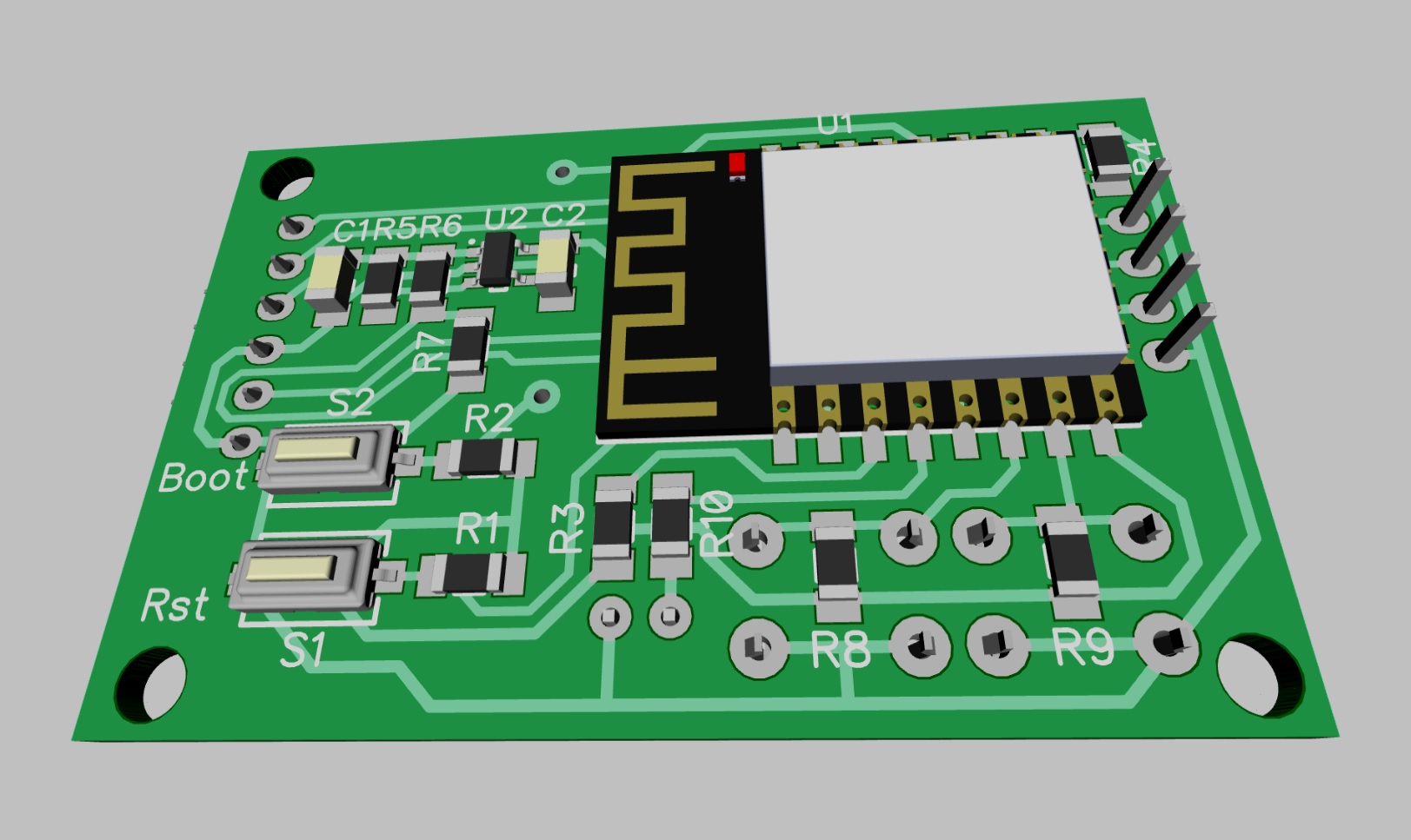
The heart of the device will be a
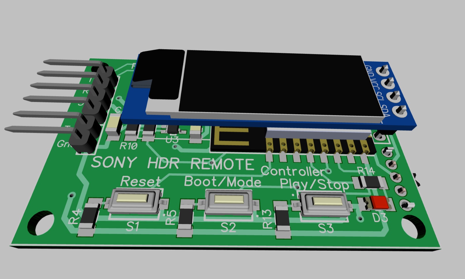
Prototype Scheme:

Board Design:
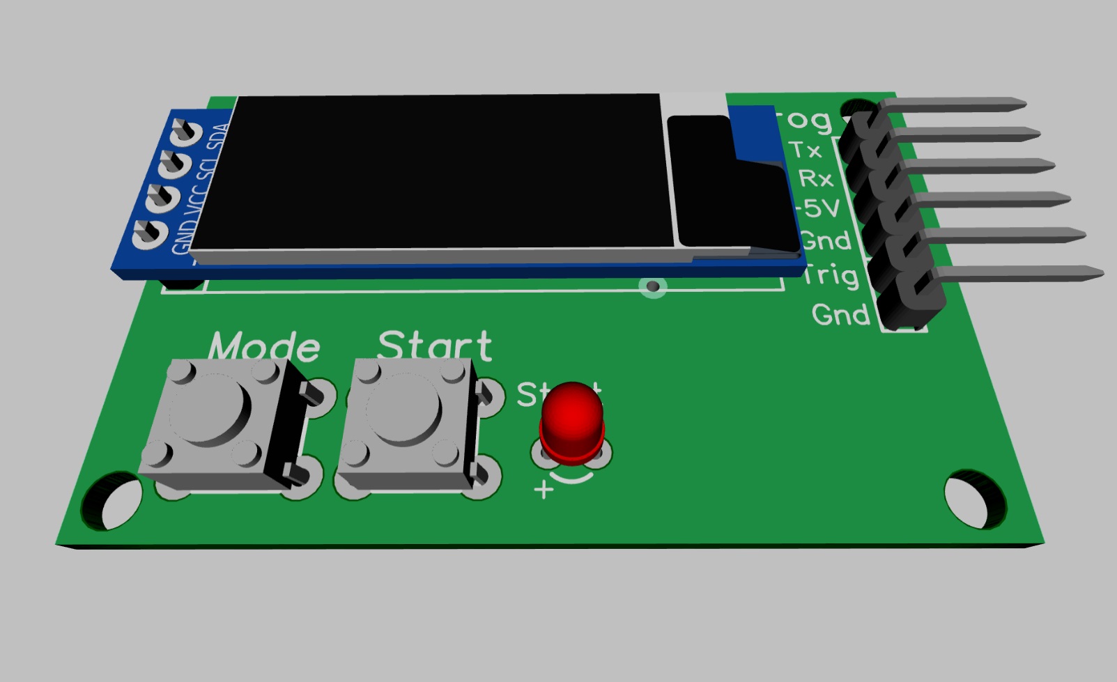
Well, the very victim of LUT:

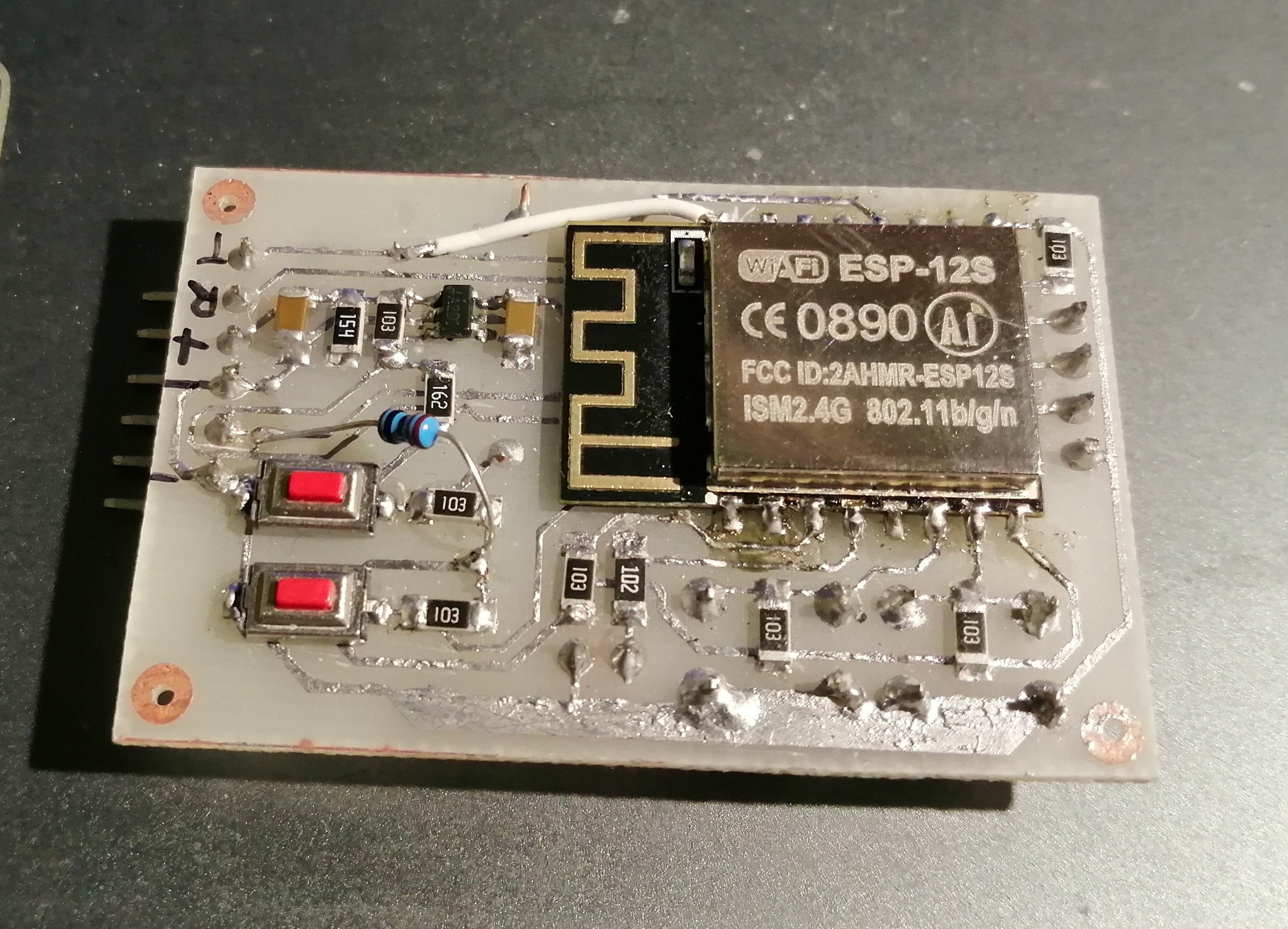
Firmware
I recommend skipping this part to arduino-haters, as I developed the firmware in Arduino IDE with ESP8266 Core installed. For convenience, I used additional libraries:
- Adafruit GFX Graphics Library
- Library work with OLED screens Adafruit SSD1306
- Library for quick and easy WiFiManager configuration
- ArduinoJson library - a convenient JSON message parser
With graphic libraries, everything is clear. They are needed to work with the OLED display. WiFiManager is a very convenient library for setting up WiFi connections in ESP. In the case of entering the settings mode, it raises the access point to ESP and its minimalistic WEB server, to which it redirects when connected. You can start in automatic mode, but then the settings mode will start every time when there is no camera connection. I chose to enter the settings mode by long pressing the “BOOT / MODE” button and exit by timeout of 120 seconds.
The WiFiManager library is also convenient in that you can add your own fields for customization (this was not useful to me in this project), as well as handle events - entering the setup mode and saving settings.
After the settings for connecting to the camera are configured, the program makes a connection, which is written on the screen. If a connection is established, the program sends a request to the camera for the current status every second and displays the changes on the screen. This is done so that you can track camera controls directly from the buttons on it.
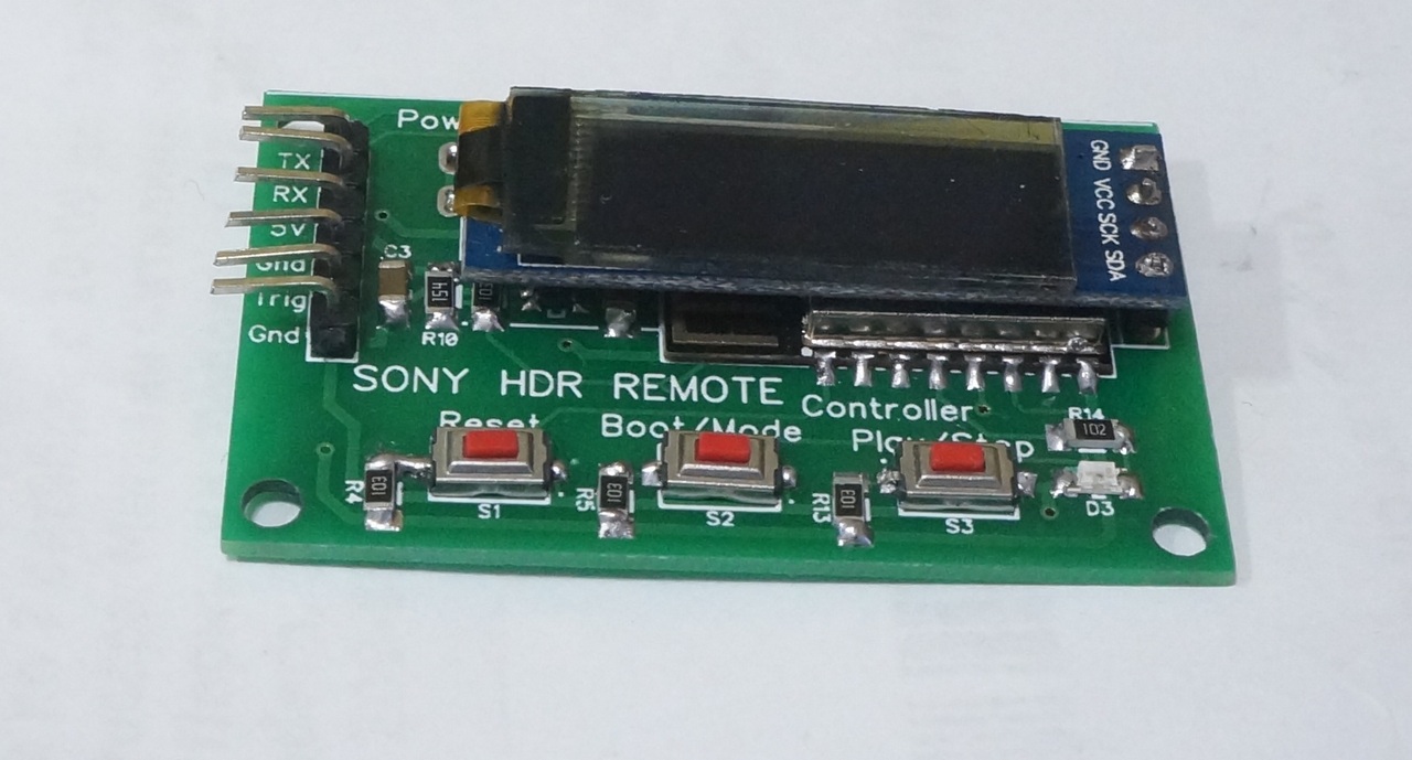
Using the “BOOT / MODE” button, we cyclically switch the three main camera modes - “VIDEO”, “PHOTO” and “LAPSE”. Use the PLAY / STOP button to turn on / off the recording in the VIDEO or LAPSE mode and record a single photo in the PHOTO mode. When recording is on, the red LED is on. When recording, the photo blinks once.
There is also an additional input on GPIO14, which essentially duplicates the “PLAY / STOP“ button. This input is needed to connect an external trigger, which can synchronize photo capture for time-lapse shots with an external event. This input I plan to connect to a 3D printer and shoot time-lapse video print parts.
Of the additional functions, the program periodically measures the values of the ADC input, to which the divider is connected directly from the battery, and gives the battery status with the icon. The program is calibrated on dividers R12 = 1.6K and R11 = 10K and a lithium battery.
Unfortunately, AS100 does not support the output in JSON of recording time and the number of shots in time-lapse mode. In sketches, these parameters are written into variables, if someone repeats, then on other cameras they can also be displayed.
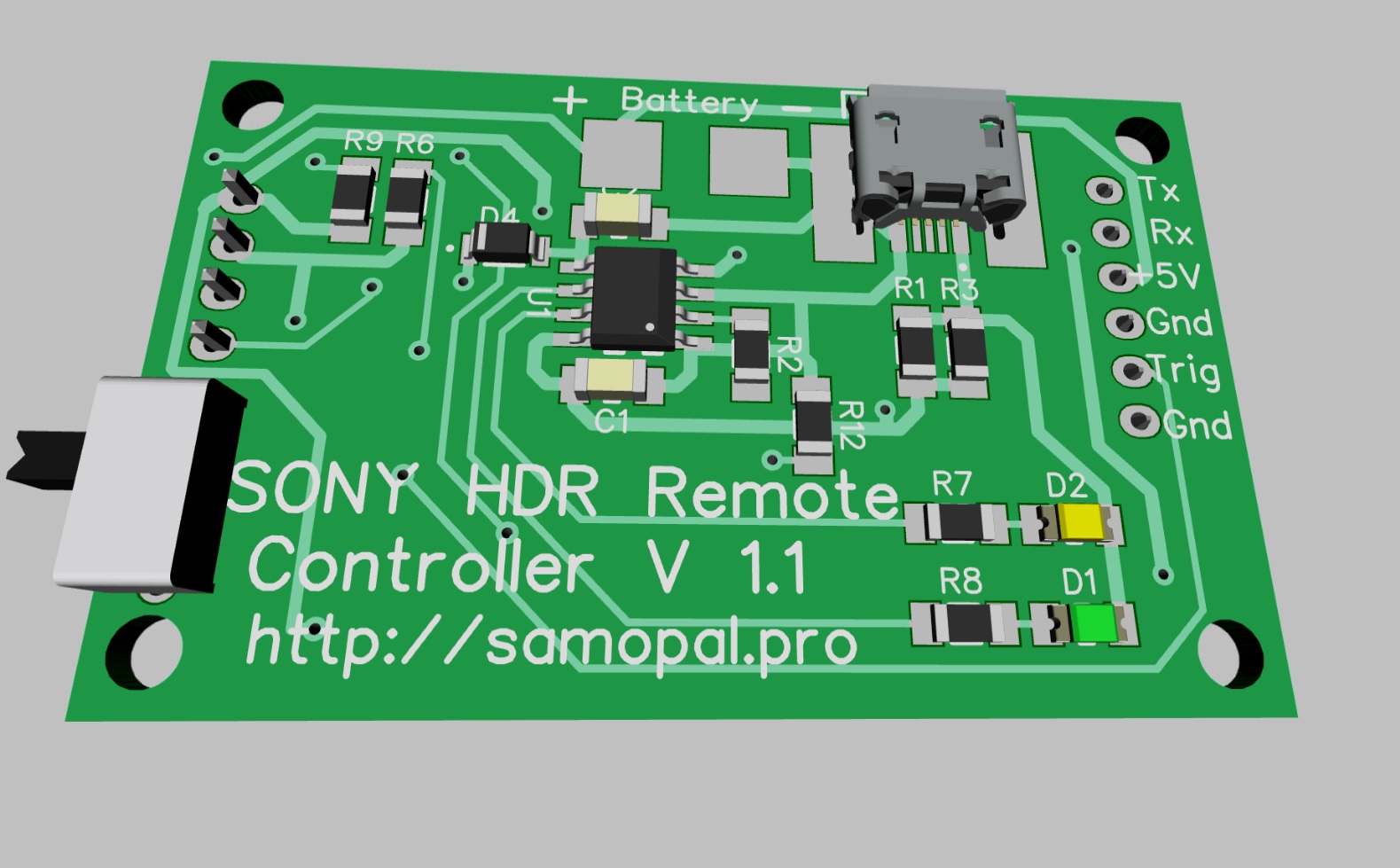
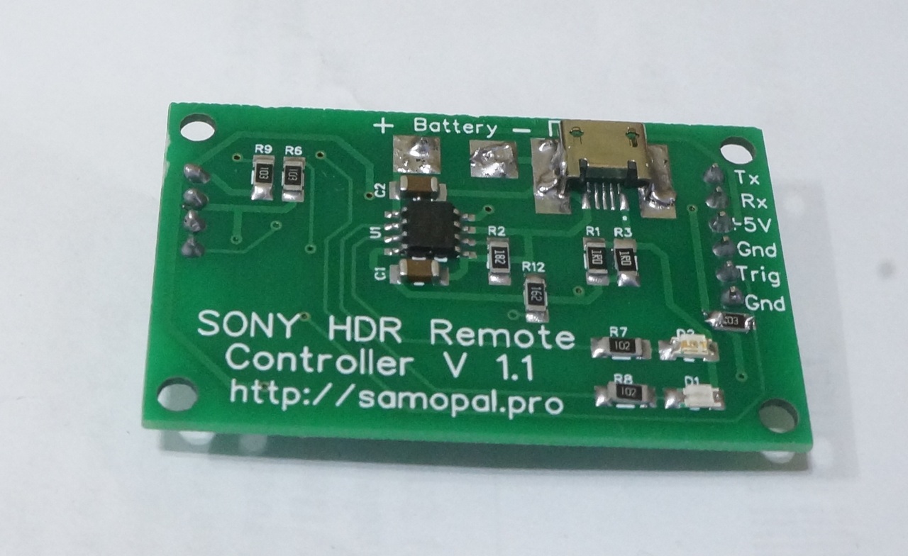
"Industrial model
Recently, I was
The design was finalized for two-way installation, and in the circuit added lithium charging on TP4056:

The Chinese timidly tried to tell me that I order several boards in one order. But we are not used to retreating - I unite all the boards with a common frame on silk-screen printing, I connect Zeil of different boards (cut anyway) and even write in Russian that this is one board)))
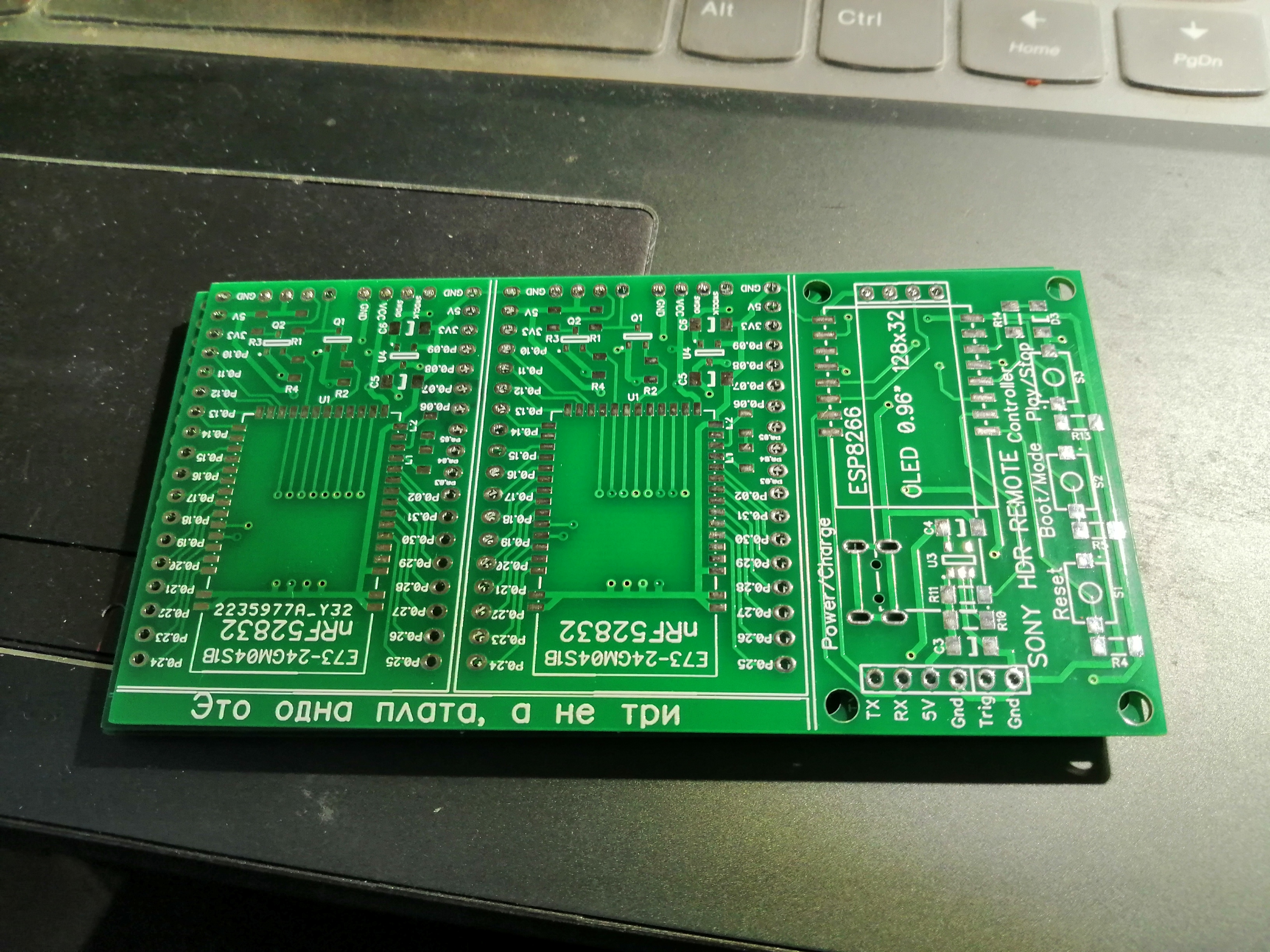
True, you have to cut the boards manually, there are good metal scissors for this.
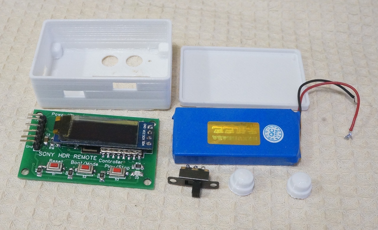
As a result, we get such a product
The simplest case on a 3D printer:

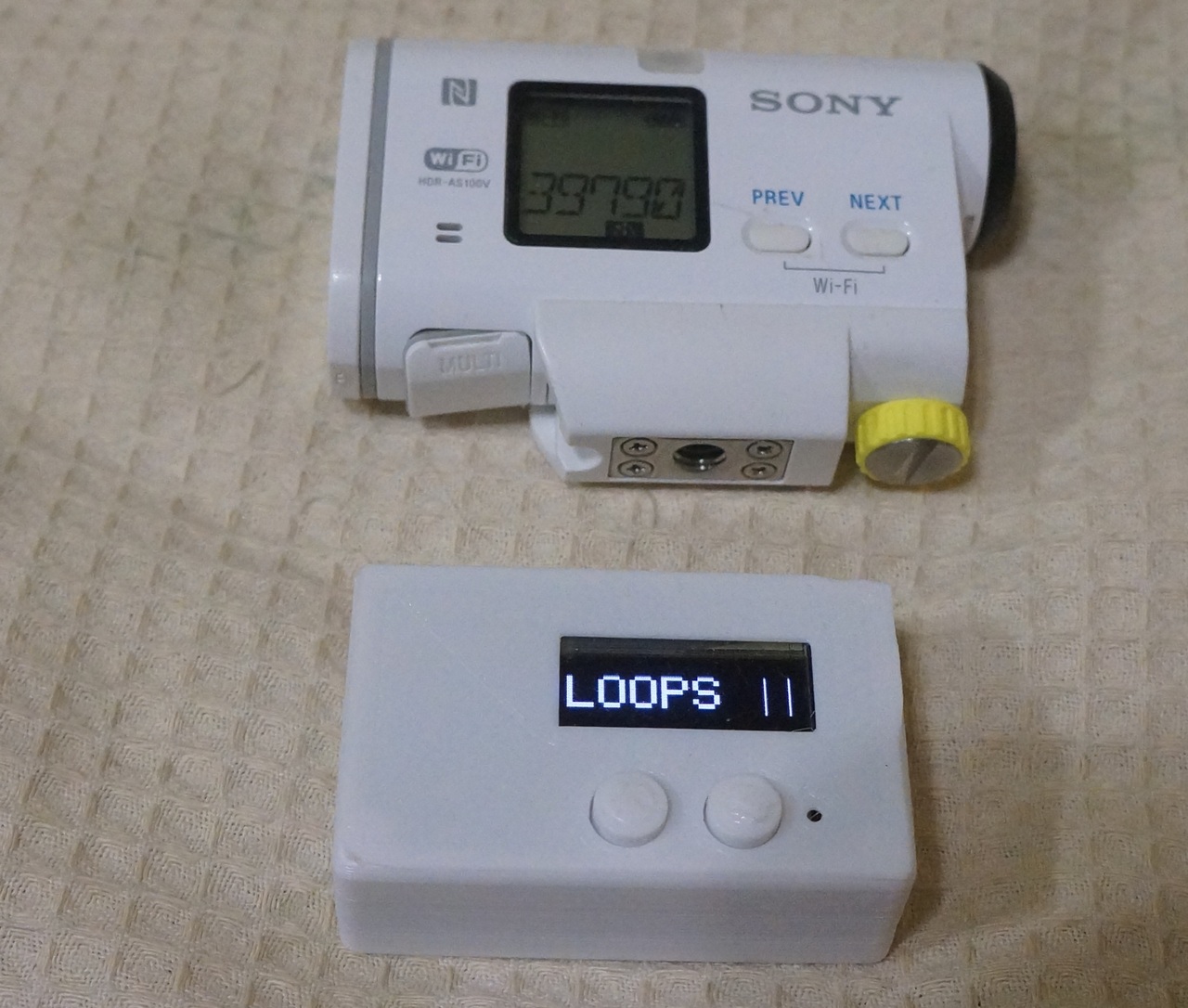
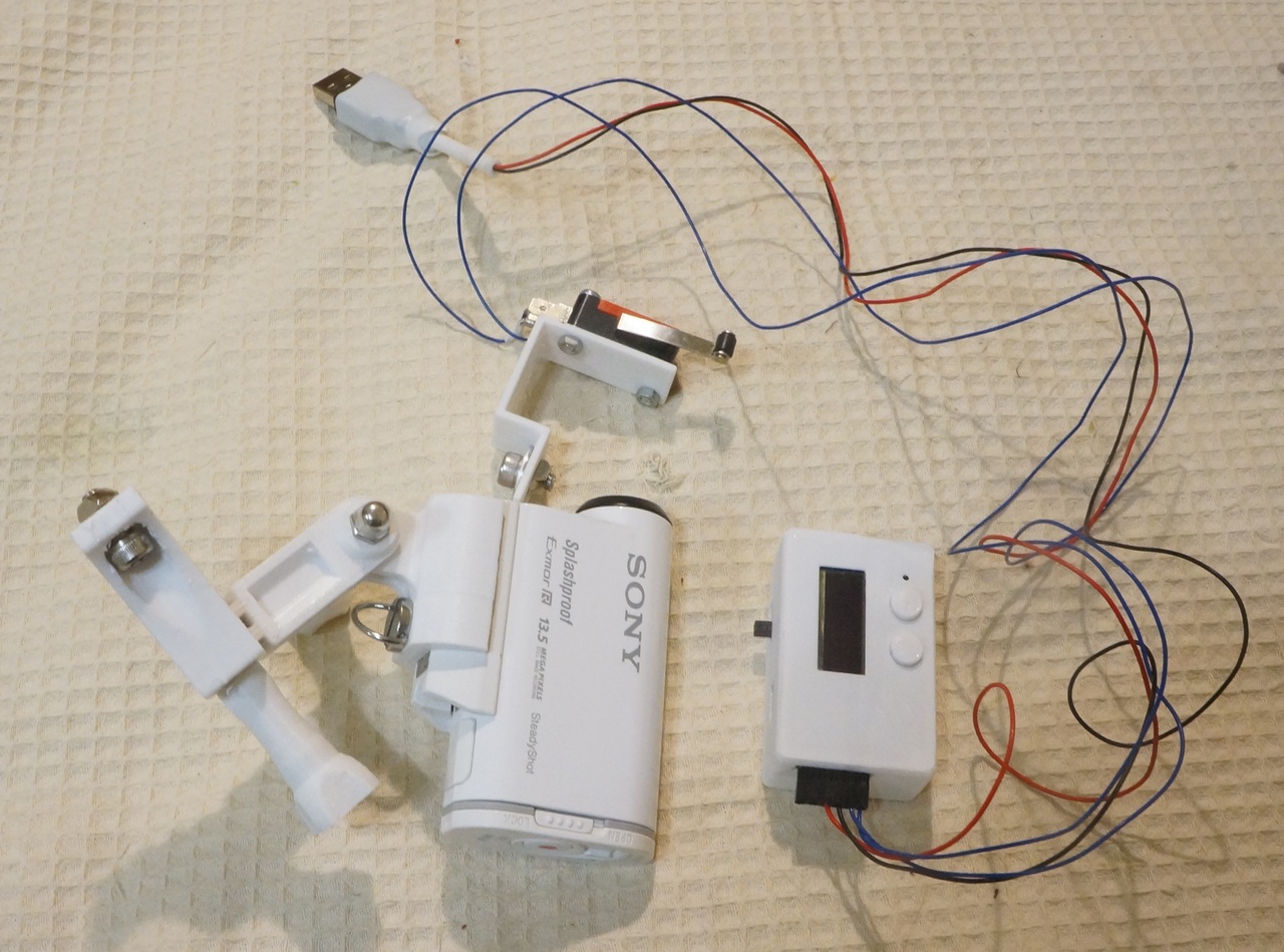
How it works:
Now a little application
What was the purpose of the input of the external trigger. I wanted to try shooting TimeLaps 3D printing using my SONY HDR AS100 camera. For this, I’m in the controller and made an input for an external trigger. There are several ways to send a signal to this input.
Connect to a free pin of the controller and sew in the printer firmware control this input using an additional G-code command.
Install OctoPrint with the OptoLapse plugin and connect the input of the remote controller to the free Orange PI / Raspberry PI port.
Install an additional limit switch connected to the controller and take the head of the printer to take pictures of each frame so that it presses this switch.
I tried the 3rd method:
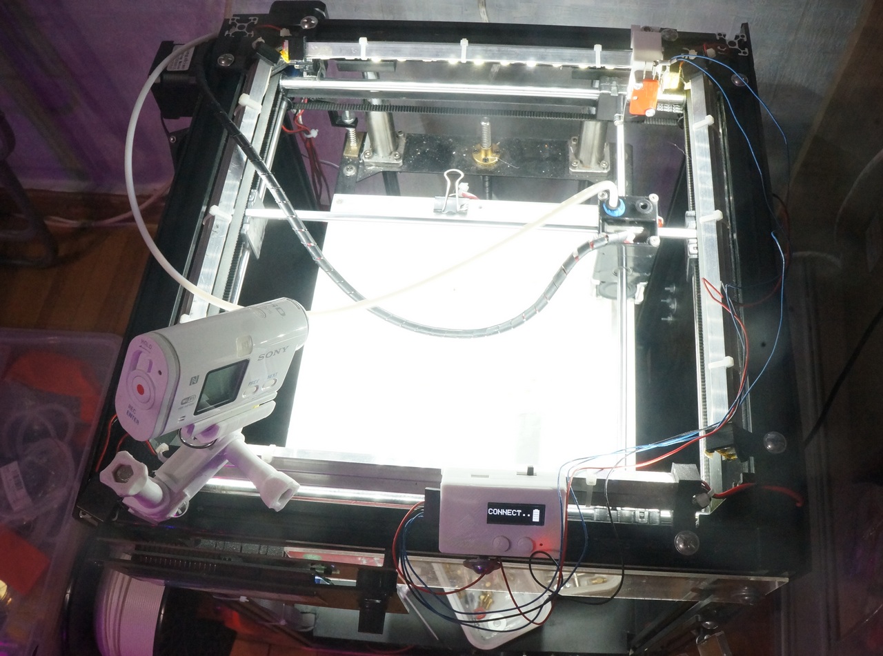
He quickly wrote a PHP script on his knee, which, after printing each layer, inserts the head retraction code into the position of the limit switch.
<?php $file1 = $argv[1]; $file2 = $argv[2]; if (!file_exists($file1)) { printf("Can't open %s\n",$file1); exit(1); } $flag = 0; $f1 = fopen($file1,"r"); $f2 = fopen($file2,"w"); while( !feof($f1) ){ $s = fgets($f1, 1024); $n = strpos($s,";LAYER:"); if( $n !== false )$flag = 1; if( $flag == 1 ){ $n1 = strpos($s,"G0 "); if( $n1 !== false ){ fprintf($f2, ";TIMELAPSE BEGIN\n"); fprintf($f2,"G10\n"); fprintf($f2, "G91\n"); fprintf($f2, "G0 F1000 Z10\n"); fprintf($f2, "G90\n"); fprintf($f2, "G0 F5000 Y230\n"); fprintf($f2, "G0 F5000 X178 Y230\n"); fprintf($f2, "G4 P1000\n"); fprintf($f2,"%s",$s); fprintf($f2,"G11\n"); fprintf($f2, ";TIMELAPSE END\n"); $flag = 0; } else { fprintf($f2,"%s",$s); } } else { fprintf($f2,"%s",$s); } } fclose($f1); fclose($f2); ?>
The G-code after each layer looks like this:
;TIMELAPSE BEGIN G91 G0 F1000 Z10 G90 G0 F5000 Y230 G0 F5000 X178 Y230 G4 P1000 G0 F6000 X93.168 Y92.836 Z0.3 ;TIMELAPSE END
Unfortunately, I couldn’t deal with the printer’s retrac straight away, so the first video came out with the name “Printing snot”)))
“But this is a completely different story” ©
The whole OpenSource project. The firmware source , board design files, circuits, and case model can be taken on GITHUB .
Original article on my blog