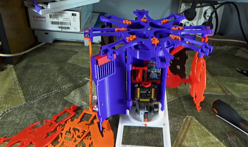
In a previous article, I talked about my new development - the demonic carousel robotic toy. I have substantially refined this model, and although the device is still inoperative (I still have to write a program), I still have something to show and tell you. The design of the target has seriously changed, and the principle of the shooting range has remained the same.
All parts of the shooting range were printed on a 3D printer, for almost 50 hours, at a speed of 50 and a layer of 0.1 mm. Printing could be faster, but then the quality of the device would suffer.
On the new version of the toy, I spent about 350 grams of filament. But, of course, it took a lot more to develop a filament model, taking into account all the trial and error.
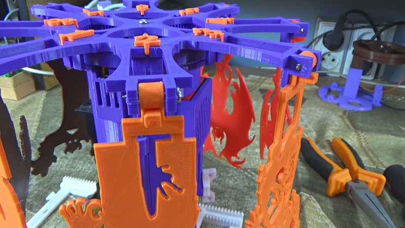
The new version of the target holder now looks more elegant, moreover, it took less filament than the previous version of this device. Also thanks to this, I was able to reduce the number of screws from two to one for attaching each of the eight targets.
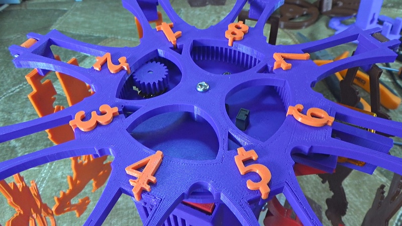
For precise target positioning, a cylindrical gear with internal gear engagement is implemented. Thus, I avoided the disadvantages of the first option, where the target holder was mounted directly on the motor shaft.

Two optocouplers set the target in the right position under the lifting device. Using optocouplers is a cheap option, so I did not use a magnetic position sensor in this model, which costs about seven dollars. I also made a trial version, with a magnetic position sensor, but it turned out that this only increases the cost of the structure, and does not make any special improvements to the operation of the device.
In order for the optocouplers to operate in the right places, there are two sectors on the back of the target holder. One sector, with one position, allows you to determine the initial position of the target. On the second sector there are eight positions that determine whether there is a target under the lifting device.
The mechanism of the lifting device with the location of the shock sensor remained almost the same, here the design has not undergone special changes.

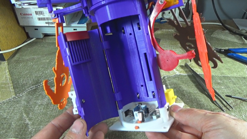
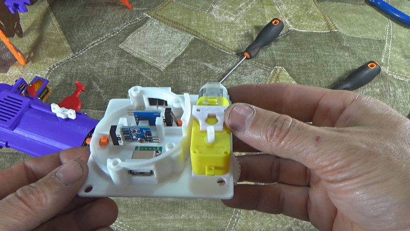
Since there is no body on the power bank, the power bank board is located at the end of the cylindrical stand, which acts as the holder of the entire target structure. The disadvantage of the design is that you need to unsolder the USB connector and the switch that are on the board of the bank, otherwise the bank will not enter its place.


I did not restrict access to the lithium battery and cover it with the case, although this can be further improved: there are special square holes in the case for this. The screws are screwed through these holes to secure the power bank to the housing. These openings may be a fastening element for the casing that conceals the lithium battery.
There are two more holes in the case. One of them allows you to connect USB charging to a power bank, and the second serves to visually monitor the status of the LEDs.
The cylindrical stand is hollow, so all the electronics used can be placed inside it. A special door is provided for access.
The boards of the modules used, including the microcontroller, are fastened to the bezel using M3 short screws. Naturally, the false panel is made of plastic, and it is also attached to the body with two screws.
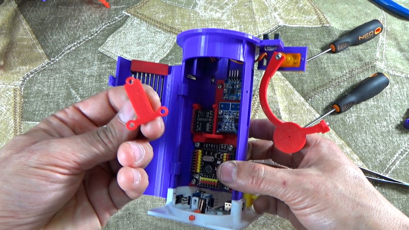
An exception was the sound module, which is not designed for screw mounting. Therefore, the sound module is fixed in a special niche. By the way, a speaker is needed for its use, and it fits perfectly into the door design.

I improved and the mobile platform. Trailer limit switches on rails are now hidden inside the casing. The transfer to the limit switches from the limit stops located on the rails takes place via pushers. These pushers are two plastic strips located in the hollow niches of the site.
In the design of the pushers, a special emphasis is designed, which does not allow the pushers to fall out of their niches.
In the future, I plan to combine other devices that have yet to be developed through a USB connector. Until I begin to specify what kind of devices these will be, I can only say that these will be very interesting projects.