In this post we will consider the stage of work with vertices. That is, we will again have to get the textbooks on mathematics and remember linear algebra, matrices and trigonometry. Hooray!
We will find out how 3D models are converted and light sources are taken into account. We will also explain in detail the difference between vertex and geometric shaders, and you will find out at what stage is the place for tessellation. To facilitate understanding, we use diagrams and code examples that demonstrate how the game performs calculations and processes values.
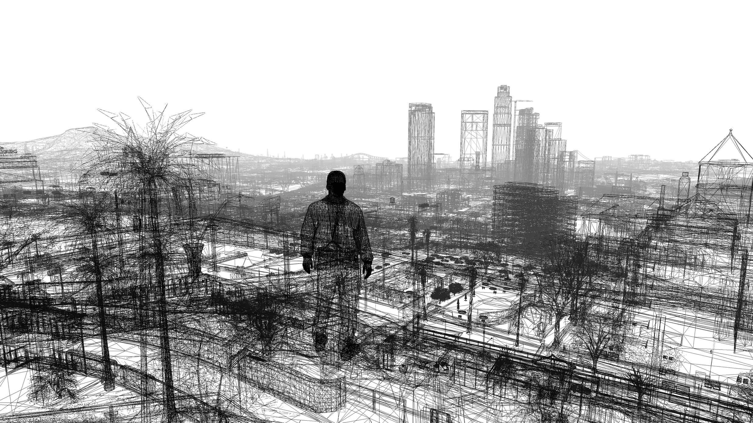
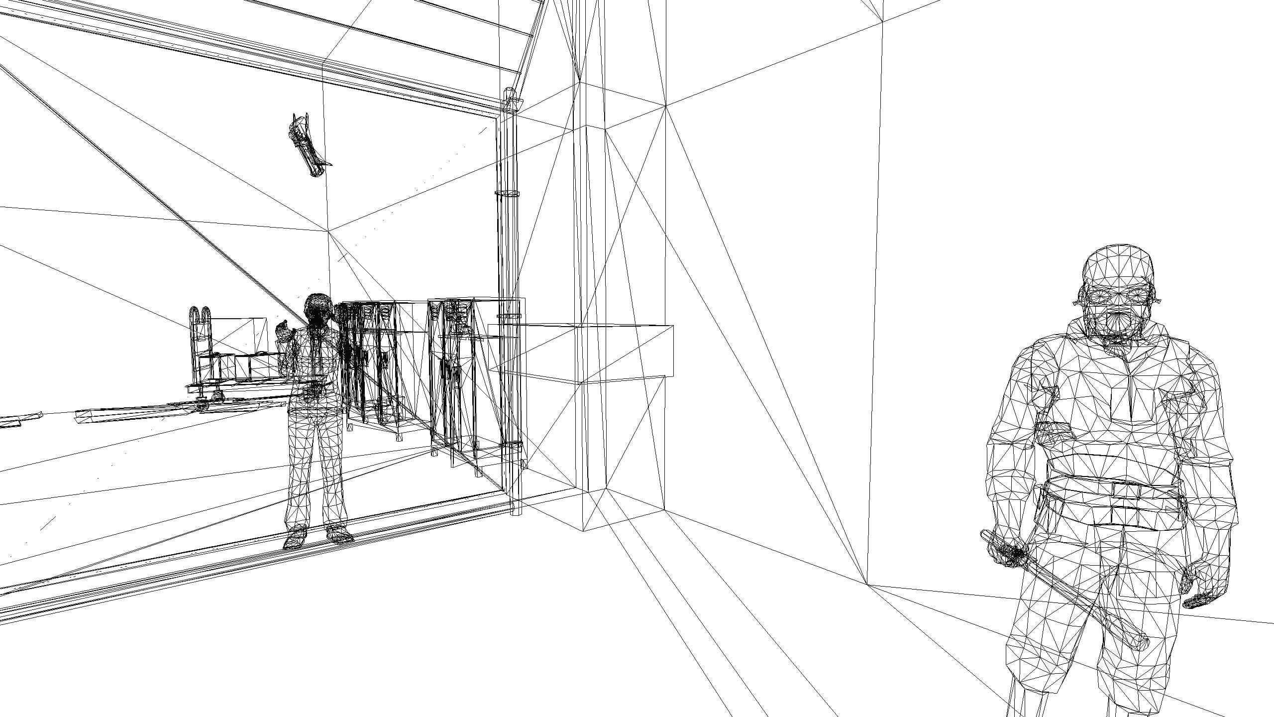
The screenshot at the beginning of the post shows the game GTA V in wireframe display mode. Compare it with the much less complex half-Life 2 wireframe display. Images were created by thalixte with ReShade .
What is the point?
In the world of mathematics, a dot is simply a place in geometric space. There is nothing smaller than a point, it has no size, so points can be used to precisely specify the location of the beginning and end of objects such as line segments, planes and volumes.
For 3D graphics, such information is critically important, the appearance of everything depends on it, because all objects are displayed as sets of line segments, planes, etc. The image below shows a screenshot from Bethesda 2015 Fallout 4 :

It may not be easy for you to see that this is just a huge bunch of dots and lines, so we will show you how the same scene looks in wireframe mode. In this mode, the 3D rendering engine skips textures and effects performed at the pixel stage and draws only multi-colored lines connecting the dots.
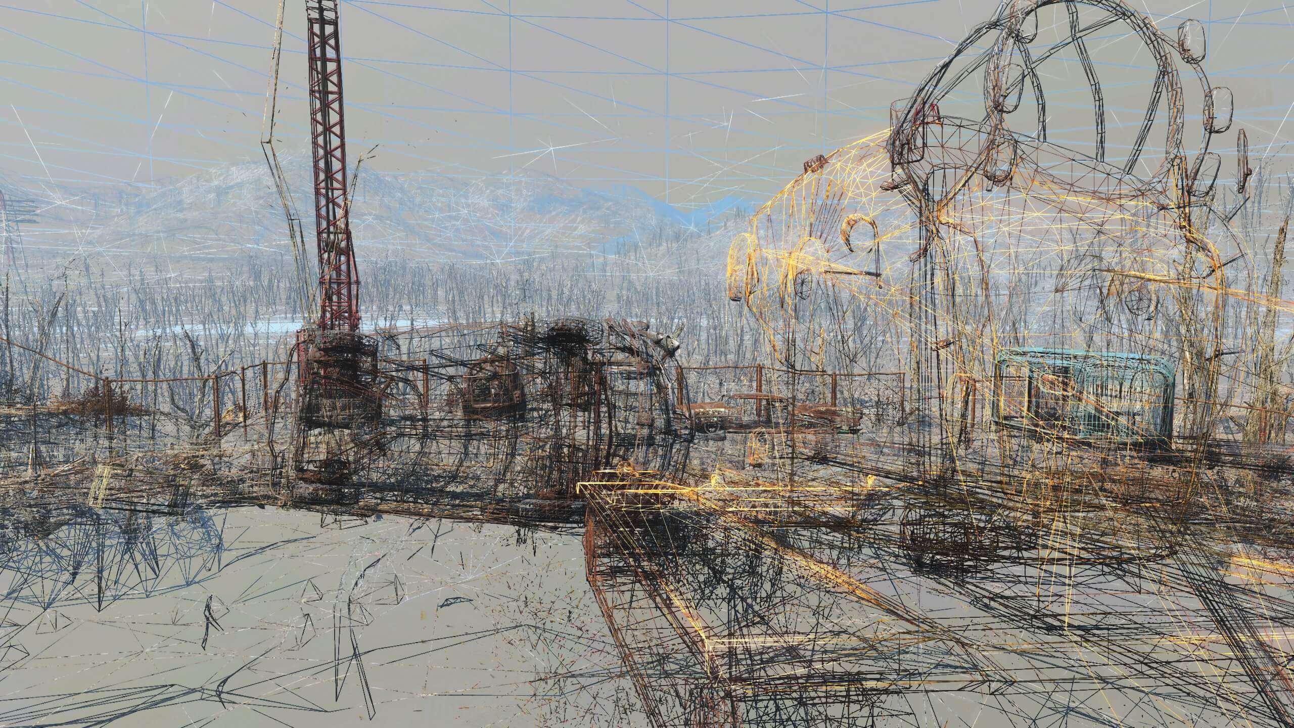
Now everything looks completely different, but we see how all the lines are combined to form various objects, environments and backgrounds. Some consist of only dozens of lines, for example, stones in the foreground, while others contain so many lines that they look solid.
Each point at the beginning and end of each line is processed by performing a whole bunch of calculations. Some calculations are very simple and fast, others are much more complicated. By processing points in groups, especially in the form of triangles, you can achieve a significant increase in productivity, so let's take a closer look at them.
What is needed for a triangle?
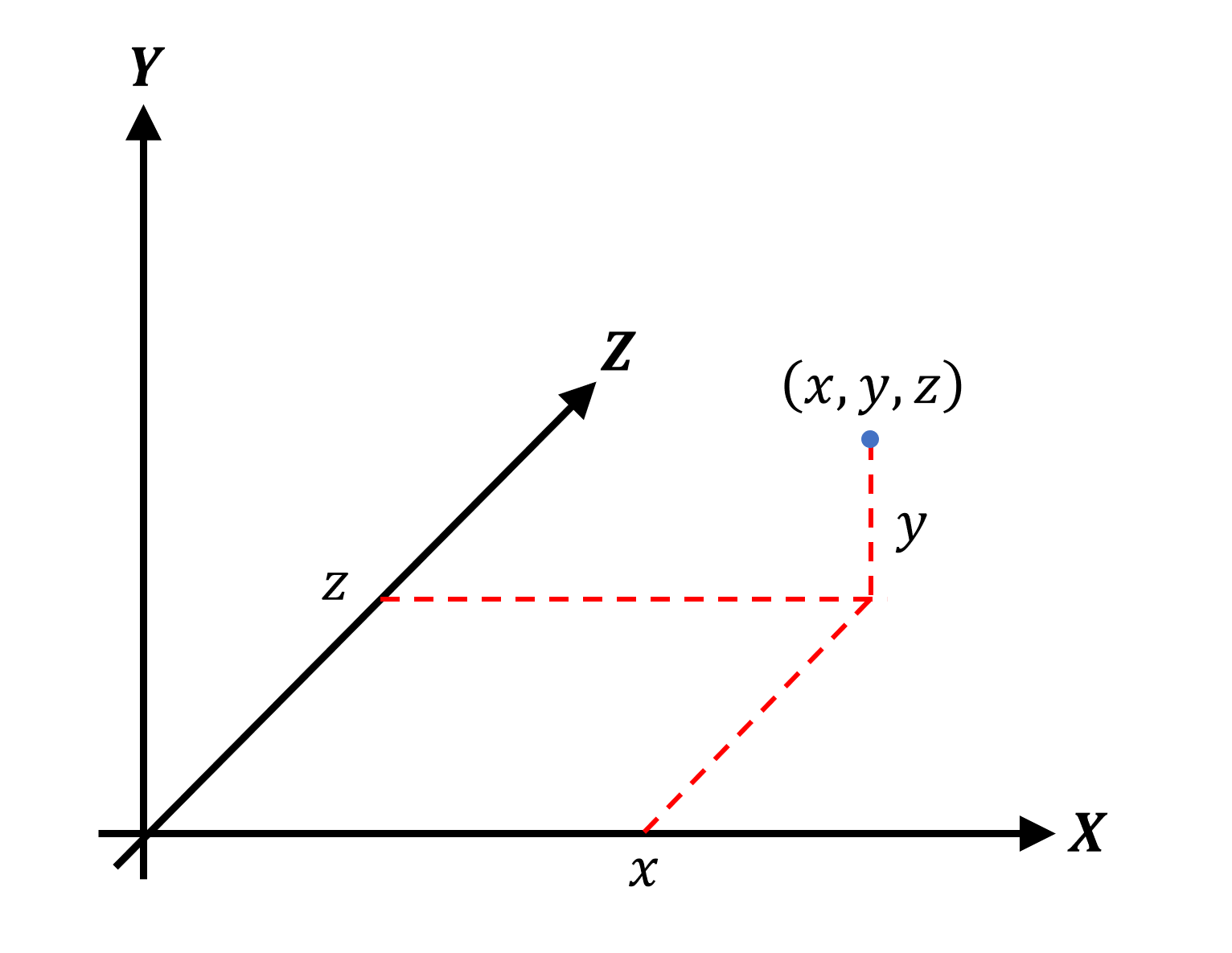
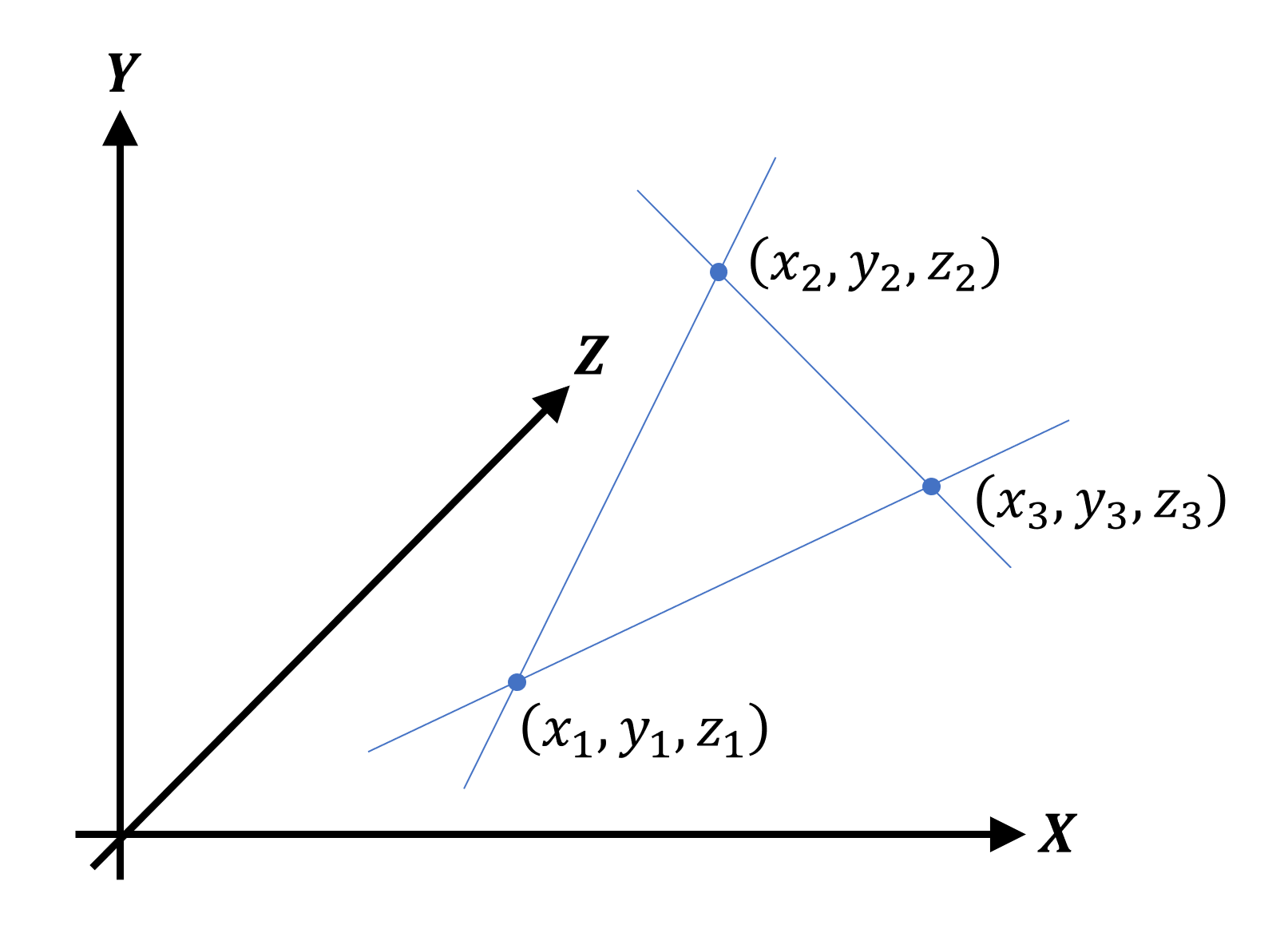
The name triangle makes it clear that the figure has three internal corners; To do this, she needs three corner points and three segments connecting them. It is correct to call a corner point a vertex (vertex) (in the plural - vertices); each vertex is defined by a point. Since we are in a three-dimensional geometric world, the Cartesian coordinate system is used for points. Usually the coordinates are written in the form of three values, for example, (1, 8, -3), or generically ( x, y, z ).
Next, we can add two more vertices to form a triangle:
Note that the lines shown are optional — we can set the points and tell the system that these three vertices form a triangle. All vertex data is stored in a contiguous block of memory called the vertex buffer ; information about the figure they form is either encoded directly in the rendering program, or stored in yet another block of memory called the index buffer .
If the information is encoded in a rendering program, then the various shapes that can be formed by vertices are called primitives . Direct3D suggests using a list for them, strips, and fans in the form of dots, lines, and triangles. When used correctly, stripes of triangles use vertices for more than one triangle, which improves productivity. In the example below, we see that to create two triangles connected together, only four vertices are needed - if they are separated, then we need six vertices.
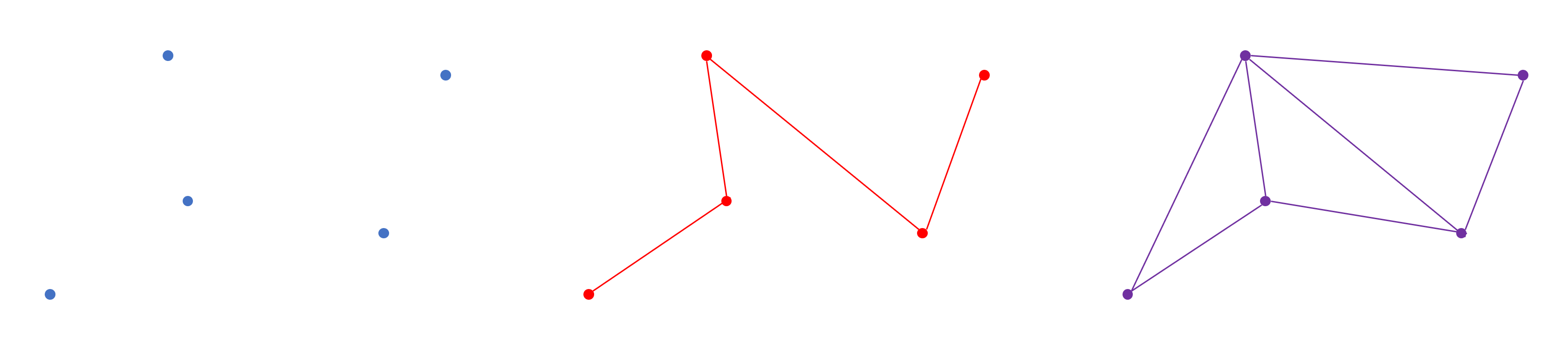
From left to right: list of points, list of lines and strip of triangles
If we need to process a larger set of vertices, for example, in a game NPC model, then it is better to use an object called a mesh , another block of memory, but consisting of several buffers (vertices, indexes, etc.) and model texture resources . Microsoft's online documentation has a brief explanation of how to use these buffers.
For now, let's focus on what happens to these vertices in a 3D game when rendering each new frame. In short, they perform one of two operations:
- The vertex moves to a new position.
- Vertex color changes
Ready for math? Excellent, because we need it.
Vector appears on stage.
Imagine that you have a triangle on the screen and you press a key to move it to the left. Naturally, we expect the numbers ( x, y, z ) of each vertex to change accordingly; that’s what happens, but a rather unexpected way of implementing the changes looks. Instead of simply changing the coordinates, the vast majority of 3D graphics rendering systems use a special mathematical tool: we mean vectors .
A vector can be represented as an arrow directed to a specific point in space and having the desired length. Vertices are usually set using vectors based on Cartesian coordinates:
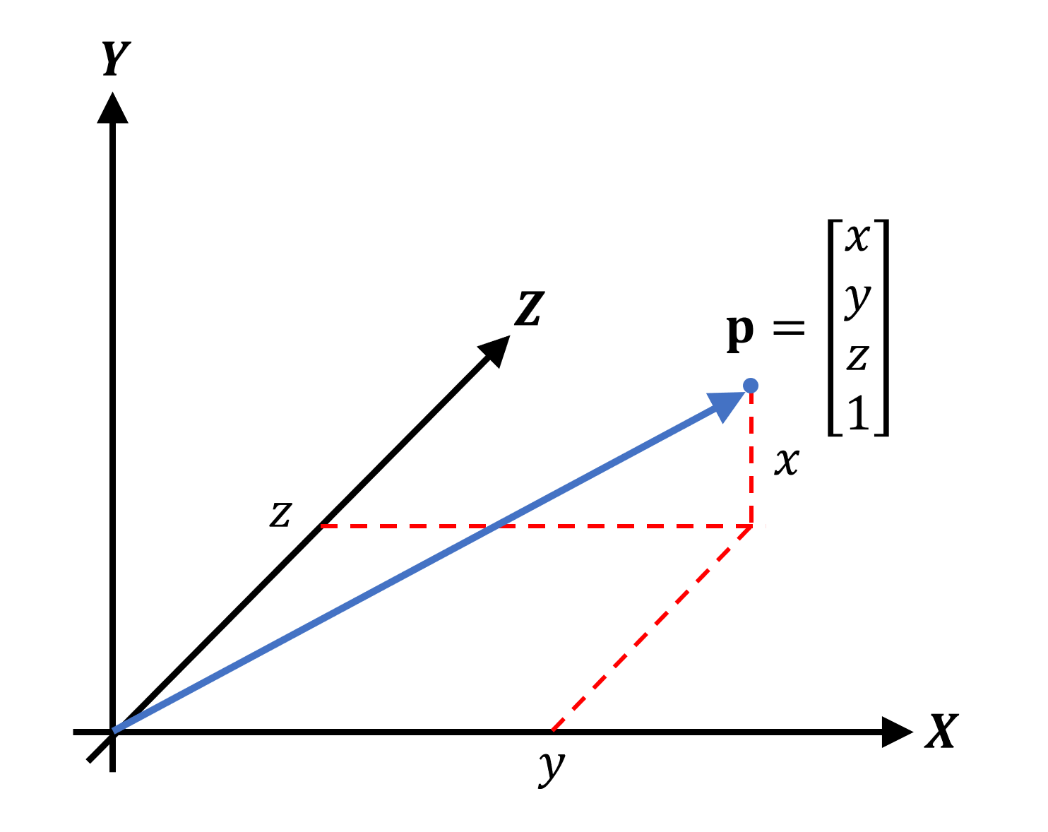
Notice that the blue arrow starts in one place (in this case, the origin point ) and extends to the top. To set the vector, we used a record in a column , but it is quite possible to use a record in a row . You may have noticed that there is another, fourth, value, commonly called a w-component . It is used to show what the vector stands for: point position ( position vector ) or general direction ( direction vector). In the case of a direction vector, it will look like this:
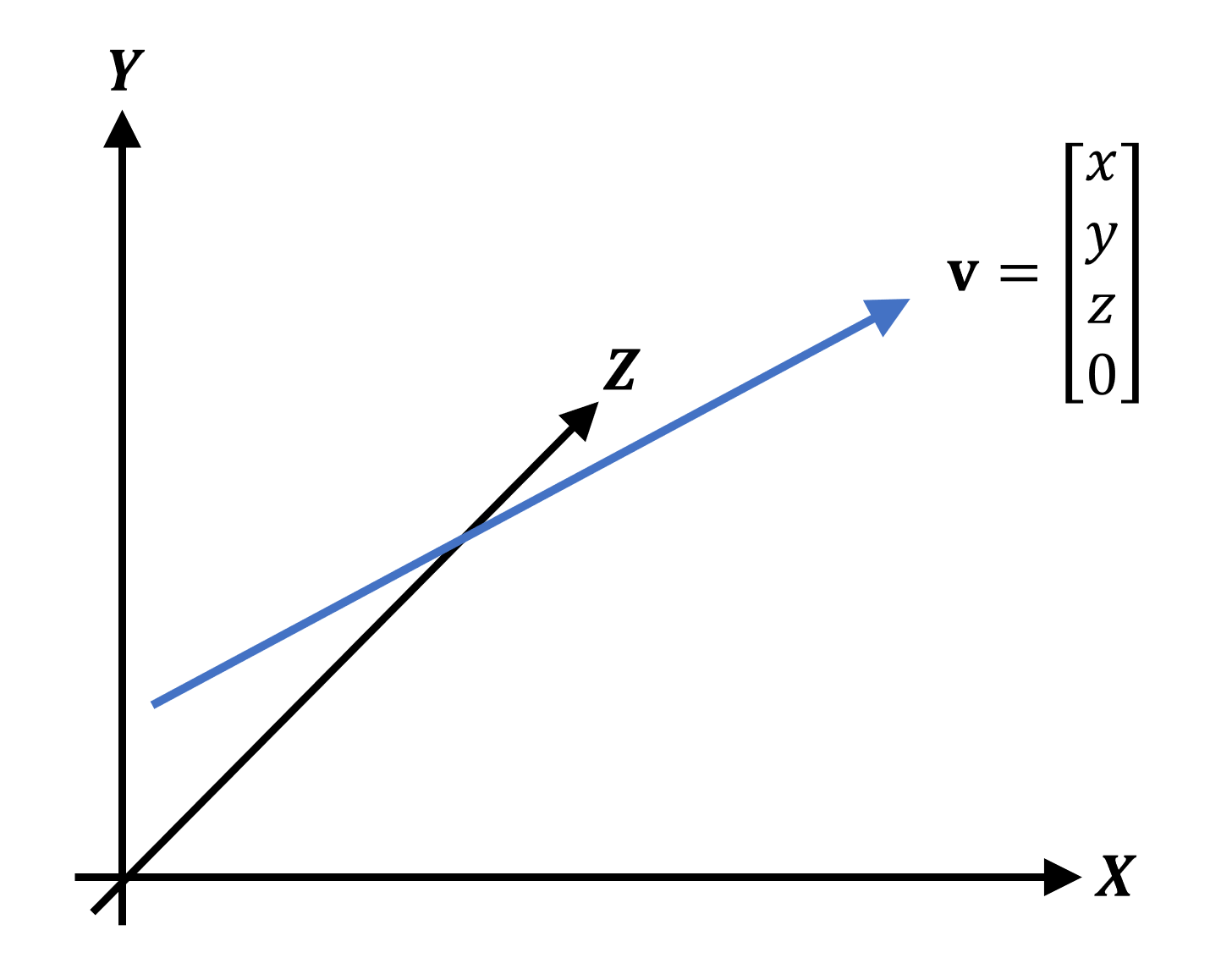
This vector points in the same direction and has the same length as the previous position vector, that is, the values ( x, y, z ) will be the same; however, the w- component is not 1, but zero. We will explain the use of direction vectors later, but for now, remember the fact that all the vertices in the 3D scene will be described in this way. Why? Because in this format it is much easier to move them.
Math, math, and again math
Recall that we have a simple triangle and we want to move it to the left. Each vertex is described by a position vector; therefore, the “movement mathematics” (called transformations ) must work with these vectors. A new tool appears: matrices ( matrix in the singular). This is an array of values written in a format similar to an Excel spreadsheet, with rows and columns.
For each type of transformation there is a corresponding matrix, and for a transformation it is enough to simply multiply the transformation matrix and the position vector. We will not go into details of how and why this happens, but just see how it looks.
Moving a vertex in 3D space is called translation, and it requires the following calculation:
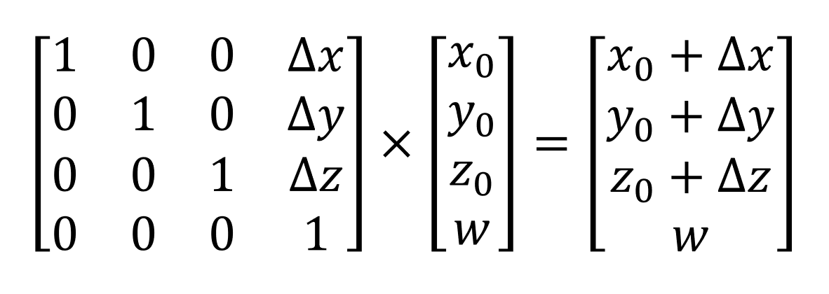
Values x 0 , etc. represent the original coordinates of the vector; delta - x values represent the amount by which the vertex needs to be moved. Multiplication of the matrix and the vector leads to the fact that they are simply summed (note that the w- component remains unchanged so that the finished answer is still the position vector).
In addition to moving, we may also need to rotate the triangle or change its scale - for these operations, there are also transformations.
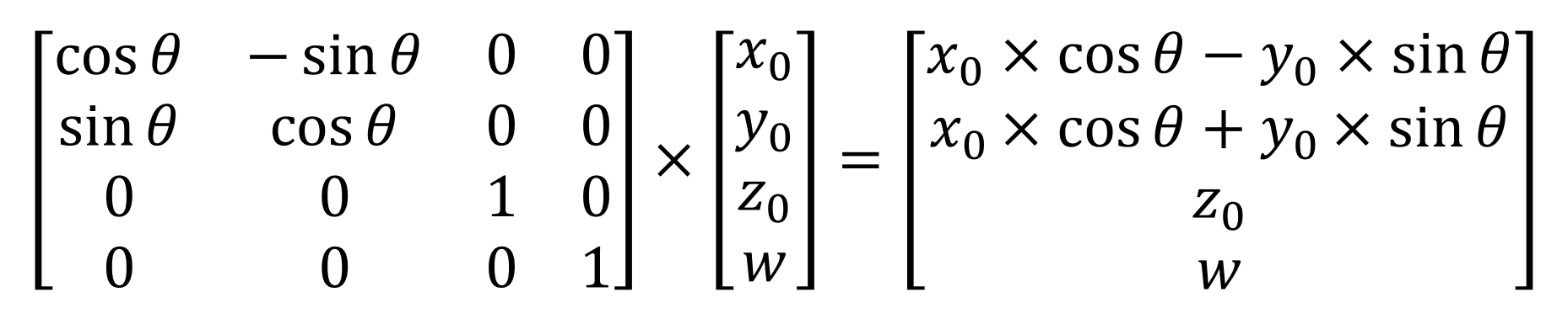
This transformation rotates the vertex around the z axis in the XY plane
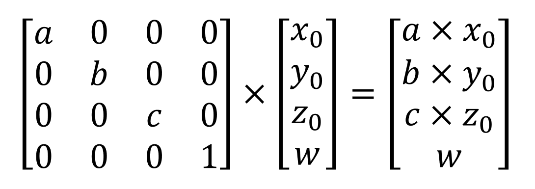
And this is used if you need to change the scale of the figure
We can use the WebGL-based graphical tool from the Real-Time Rendering website to visualize these calculations for the entire figure. Let's start with the rectangular box in the standard position:
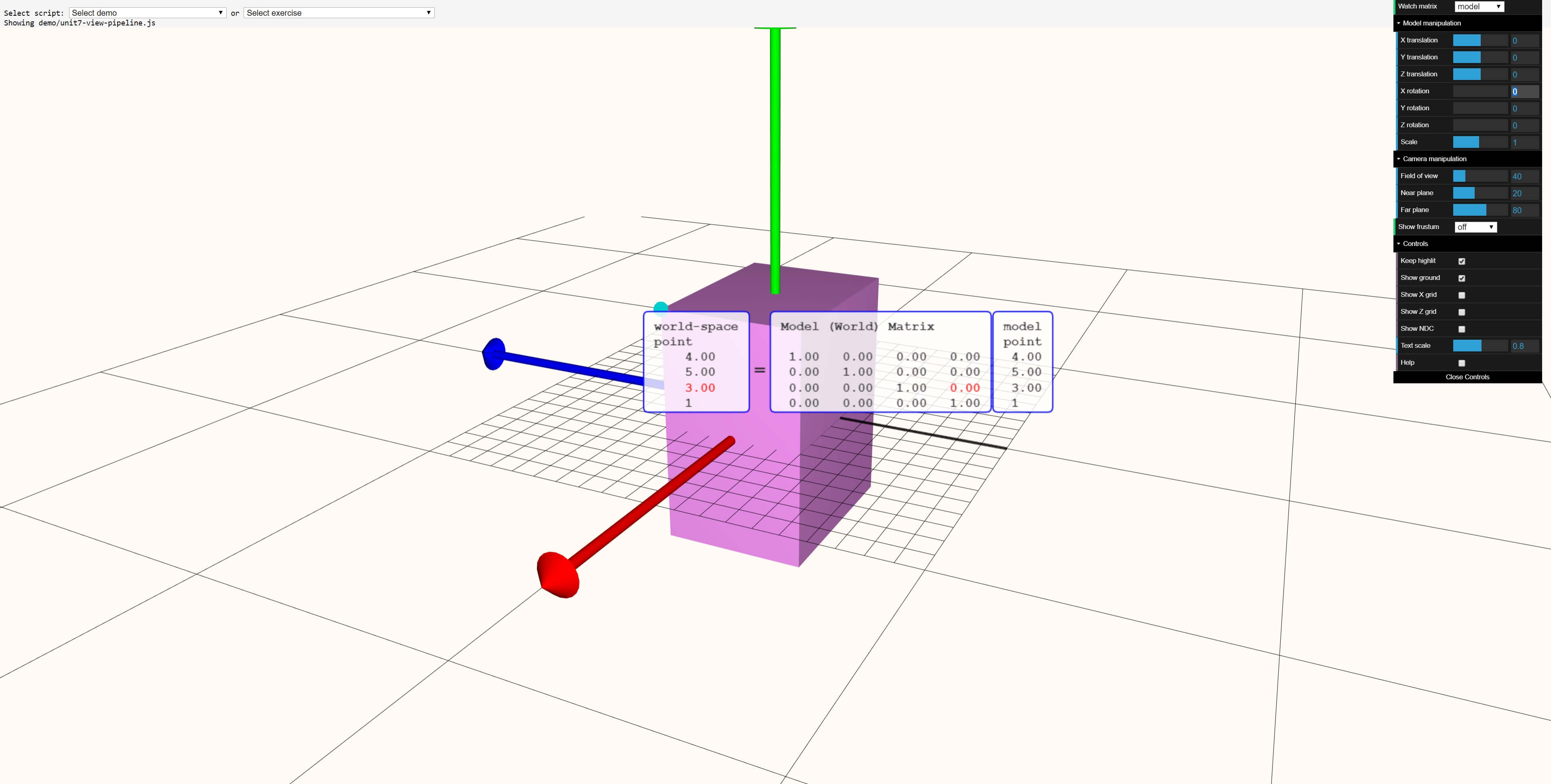
In this online tool, the model point is the position vector, the world matrix is the transformation matrix, and the world-space point is the position vector for the transformed vertex.
Let's apply various transformations to the box:

In the image above, the figure was moved 5 units on each axis. These values can be seen in the last column of the middle large matrix. The original position vector (4, 5, 3, 1) remains the same as it should, but the transformed vertex is now moved to (9, 10, 8, 1).
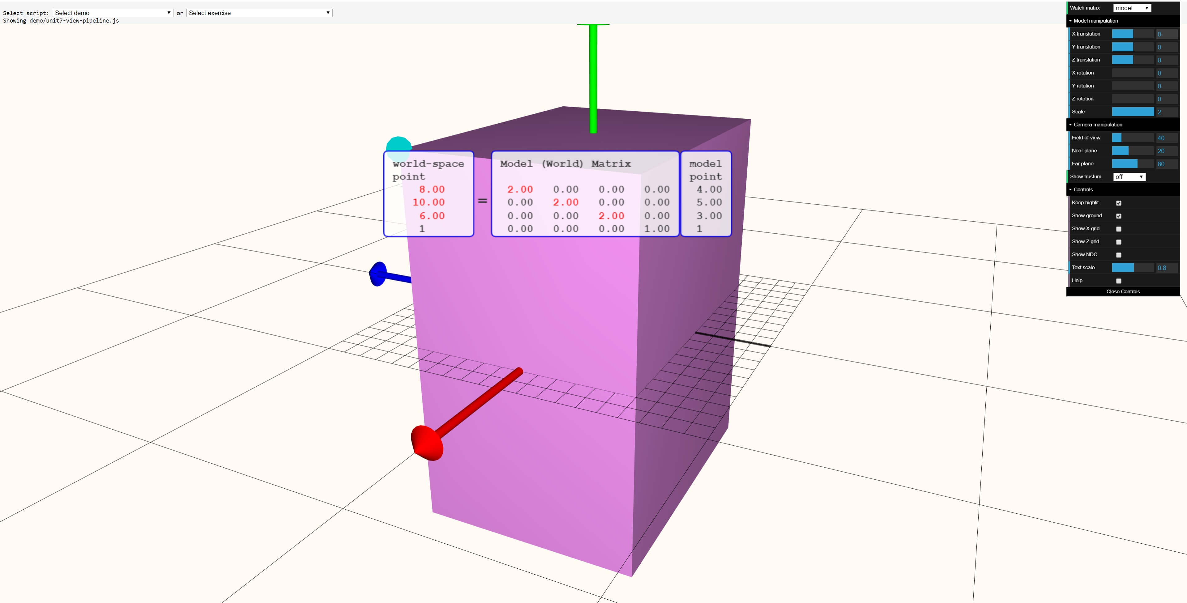
In this transformation, everything was scaled by a factor of 2: now the sides of the box have become twice as long. Finally, look at the rotation example:
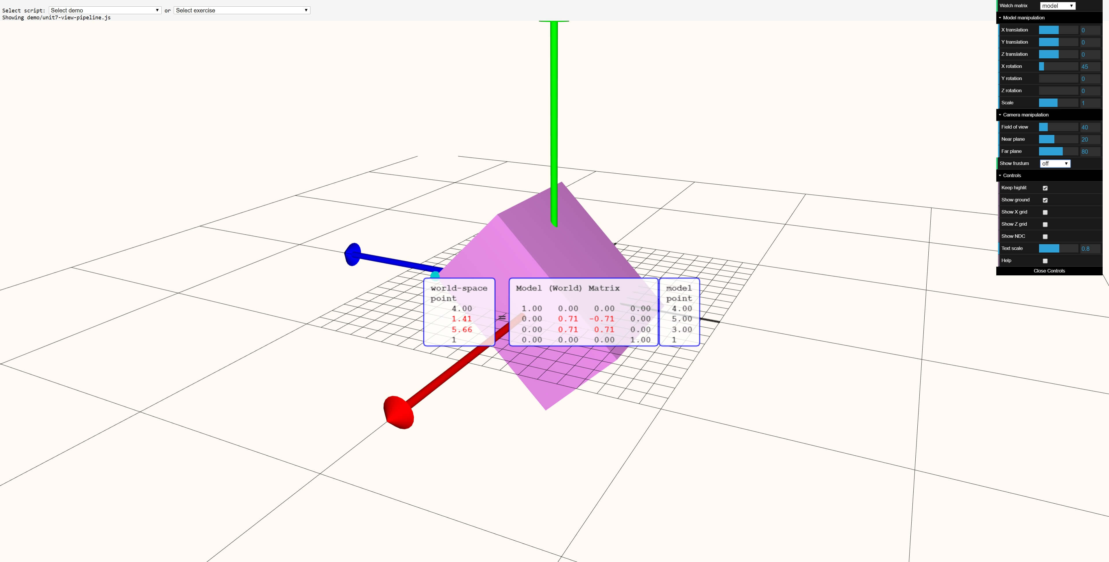
The parallelepiped was rotated at an angle of 45 °, but the sine and cosine of this angle are used in the matrix. Having checked on a scientific calculator, we can see that sin (45 °) = 0.7071 ..., which is rounded to the shown value of 0.71. We get the same answer for the cosine value.
Matrices and vectors are optional; A popular alternative for them, especially when handling complex corners, is the use of complex numbers and quaternions . These calculations are very different from vectors, so we will not consider them, continuing to work with transformations.
Vertex Shader Power
At this stage, we need to understand that all this is done by people programming the rendering code. If a game developer uses a third-party engine (for example, Unity or Unreal), then all this has already been done for him; but if someone makes his engine from scratch, then he will have to perform all these calculations with vertices.
But how does all this look in terms of code?
To understand this, we will use examples from the amazing Braynzar Soft website. If you want to start working with 3D programming yourself, then this is the right place to learn the basics, as well as more complex things ...
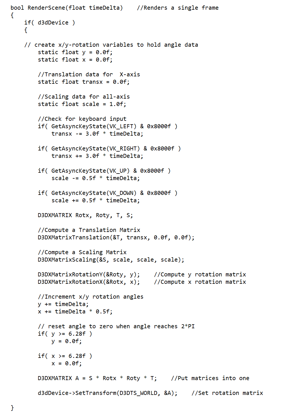
This is an example of an all-in-one transformation. It creates the appropriate transformation matrices based on keyboard input, and then applies them to the original position vector in one operation. Note that this is always done in the given order (scaling - rotation - transfer), because any other way will completely ruin the result.
Such blocks of code are called vertex shaders , their complexity and size can vary enormously. The example shown above is simple, it is only a vertex shader that does not use the full programmable nature of shaders. A more complex sequence of shaders could transform objects in 3D space, process their appearance from the point of view of the scene camera, and then transfer data to the next stage of the rendering process. Considering the order of vertex processing, we will study other examples.
Of course, they can be used for much more, so when playing a 3D game, do not forget that all the movement that you see is made by a GPU that executes vertex shader commands.
However, this was not always the case. If you go back to the mid-end of the 1990s, then the graphics cards of that era did not have the ability to independently process vertices and primitives, all this alone was done by the central processor.
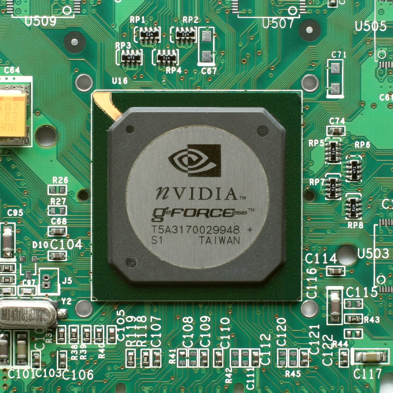
One of the first processors with their own hardware acceleration of this process was Nvidia GeForce, released in 2000 , and this functionality was called Hardware Transform and Lighting (for short, Hardware TnL). The processes that this equipment could handle were very limited in terms of teams, but with the release of new chips, the situation changed rapidly. Today, there is no separate equipment for processing vertices, and one device deals with everything at once: points, primitives, pixels, textures, etc.
By the way, about lighting : it’s worth noting that we see everything thanks to the light, so let's see how it can be processed at the vertex stage. To do this, we need to take advantage of what we talked about earlier.
Light, camera, motor!
Imagine this picture: the player is standing in a dark room, illuminated by one light source on the right. In the middle of the room is a huge kettle. You may need help with this, so let's use the Real-Time Rendering website and see how it looks:
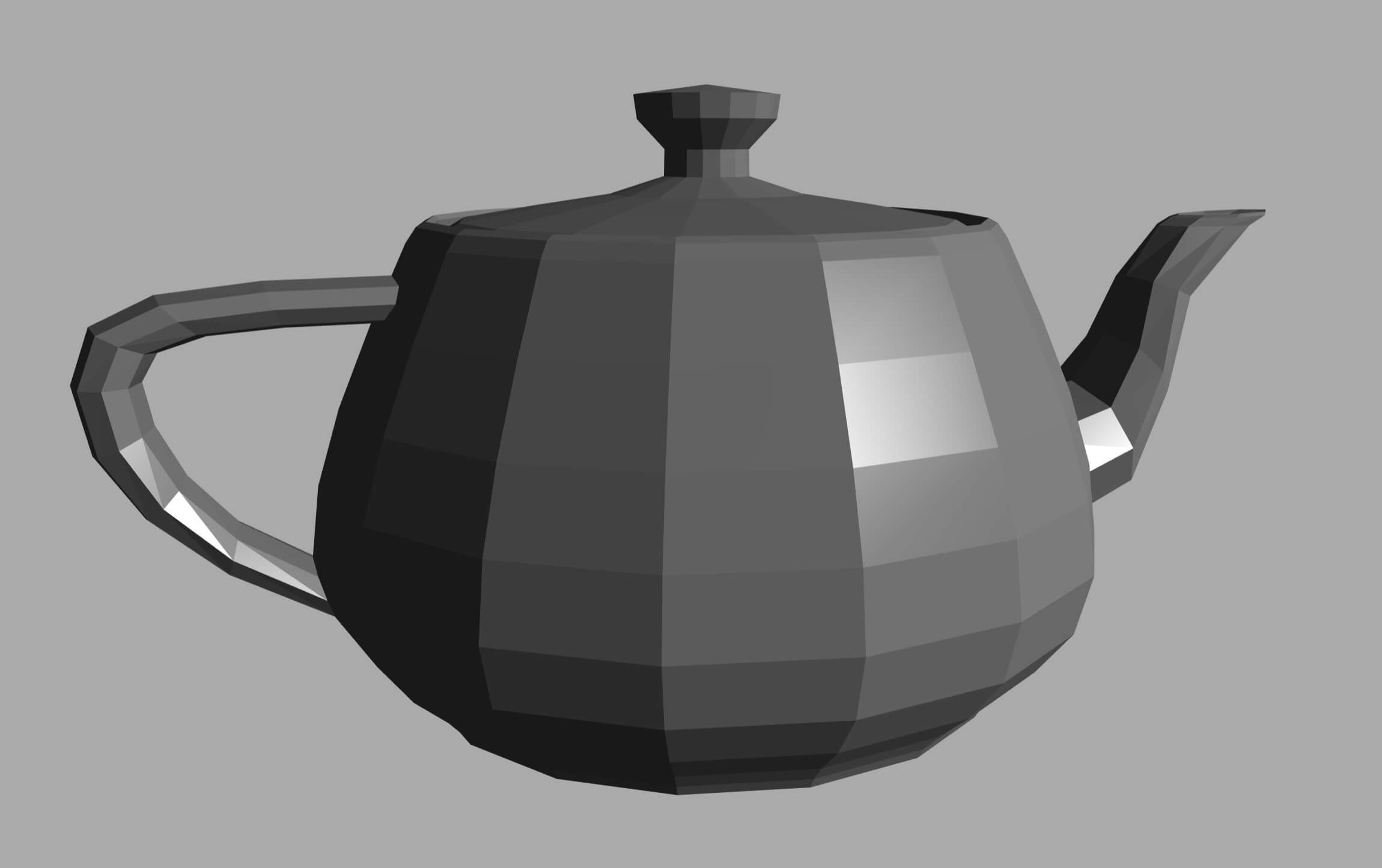
Do not forget that this object is a set of flat triangles connected together; that is, the plane of each triangle will be directed in a certain direction. Some of them are directed towards the camera, some towards the other, some will be distorted. Light from the source falls on each plane and is reflected from it at a certain angle.
Depending on where the light is reflected, the color and brightness of the plane can change, and for the color of the object to look right, all this needs to be calculated and taken into account.
To begin with, we need to find out where each plane is directed, and for this we need the normal vector of the plane. This is another arrow, but unlike the position vector, its size is not important (in fact, after calculating the scale of the normal vectors always decreases so that they have a length of 1), and it is always directed perpendicular (at right angles) to the plane.
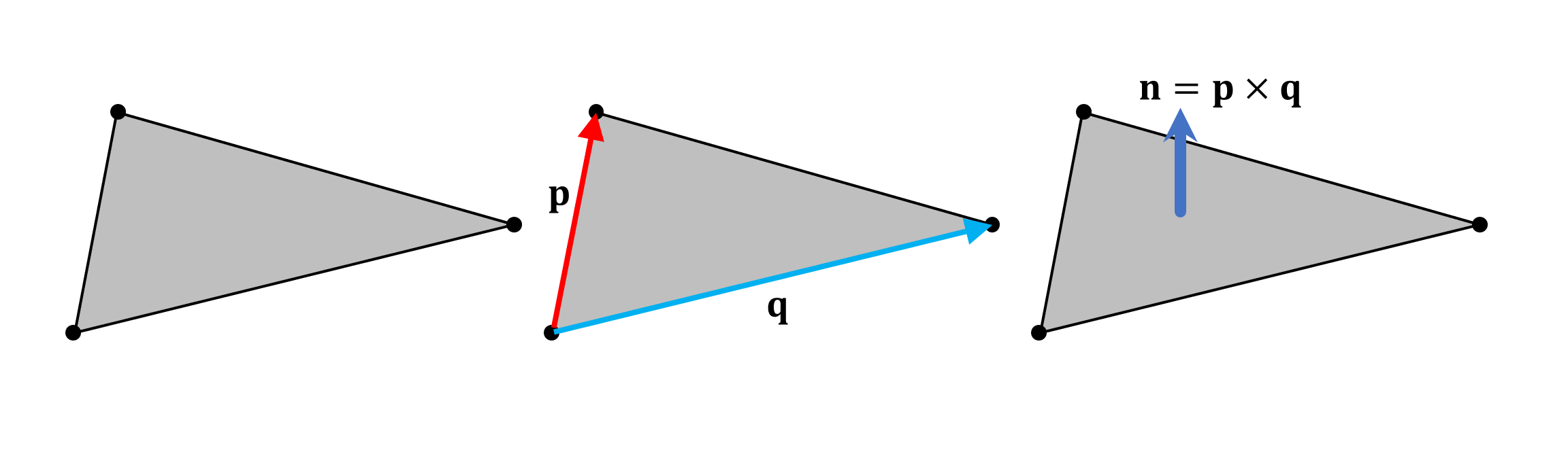
The normal to the plane of each triangle is calculated by determining the vector product of two direction vectors (shown above p and q ) that form the sides of the triangle. In fact, it is better to calculate them for each vertex, and not for a triangle, but since there are always more of the first than the second, it will be faster to calculate the normals for the triangles.
Having received the normal to the surface, you can begin to consider the light source and camera. In 3D rendering, light sources can be of different types, but in this article we will consider only directional sources, for example, spotlights. Like the plane of the triangle, the spotlight and camera will point in a certain direction, something like this:

The light source vector and the normal vector can be used to calculate the angle at which light falls on the surface (using the relationship between the scalar product of the vectors and the product of their size). The vertices of the triangle will contain additional information about their color and material. Material describes what happens to light when it hits the surface.
A smooth metal surface will reflect almost all the incident light at the angle at which it fell, and barely change the color of the object. Rough matte material scatters light in a less predictable way and changes color slightly. To take this into account, you need to add additional values to the vertices:
- Original base color
- Ambient Material Attribute - a value that determines how much “background” lighting can absorb and reflect a vertex
- The attribute of the Diffuse material is another value, but this time determining the “roughness” of the vertex, which, in turn, affects the amount of absorption and reflection of the scattered light
- Specular Material Attributes - Two Values That Specify the Vertex Gloss
Different lighting models use different mathematical formulas to group all of these attributes, and the result of the calculation is the outgoing lighting vector. In combination with the camera vector, it allows you to determine the overall appearance of the triangle.
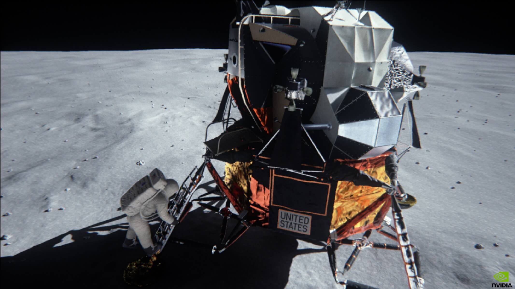
One directional light source illuminates many different Nvidia demos
We omitted many detailed details, and for good reason: open any 3D rendering tutorial, and you will see that whole chapters are devoted to this process. However, in modern games, the bulk of all calculations of lighting and material effects are performed at the pixel processing stage, so we will return to them in the next article.
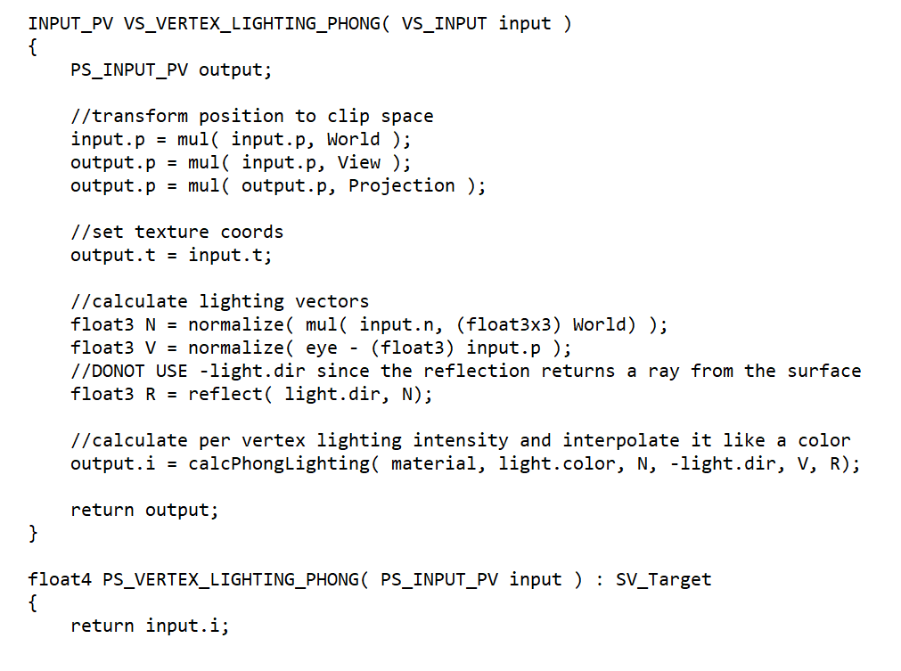
Sample code B. Anguelov showing how the Phong light reflection model can be processed in the vertex shader.
Everything that we examined above is done by vertex shaders, and it seems that nothing is impossible for them; unfortunately this is not so. Vertex shaders cannot create new vertices, and each shader must process each individual vertex. It would be convenient if you could use the code to create new triangles between those that we already have (to improve visual quality), and have a shader that processes the whole primitive (to speed up processing). Well, in modern GPUs we can do it!
Please sir, I want more (triangles)
Modern graphics chips are extremely powerful and capable of performing millions of matrix-vector calculations every second; they easily cope with a huge pile of peaks at a time. On the other hand, the creation of highly detailed models for rendering is a very long process, and if the model is located at some distance from the scene, then all these details will be wasted.
That is, we need to somehow order the processor to split a large primitive, for example, one flat triangle into a set of smaller triangles located inside the original one. Such a process is called tesselation, and graphic chips have already learned to perform it very well; over the years of development, the degree of control that programmers have over this process has increased.
To look at this in action, we will use the Heaven benchmark tool of the Unigine engine , because it allows us to apply different tessellation values to the models used in the test.
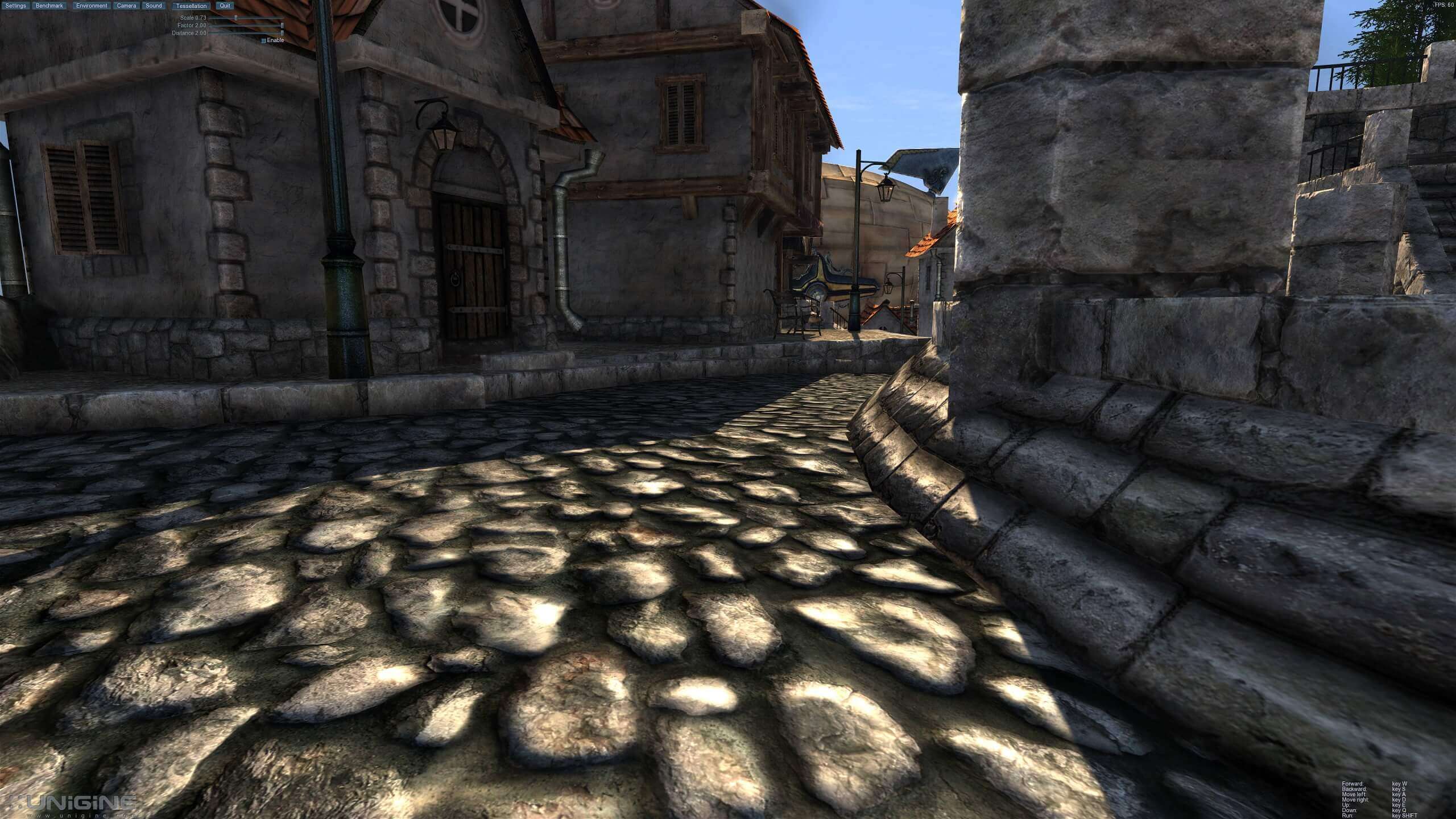
To begin, let's take a place in the benchmark and study it without using tessellation. Note that the cobblestones on the ground look very unnatural - the texture used is effective, but it seems wrong. Let's apply tessellation to the scene: the Unigine engine applies it only to individual parts, but the difference will be significant.
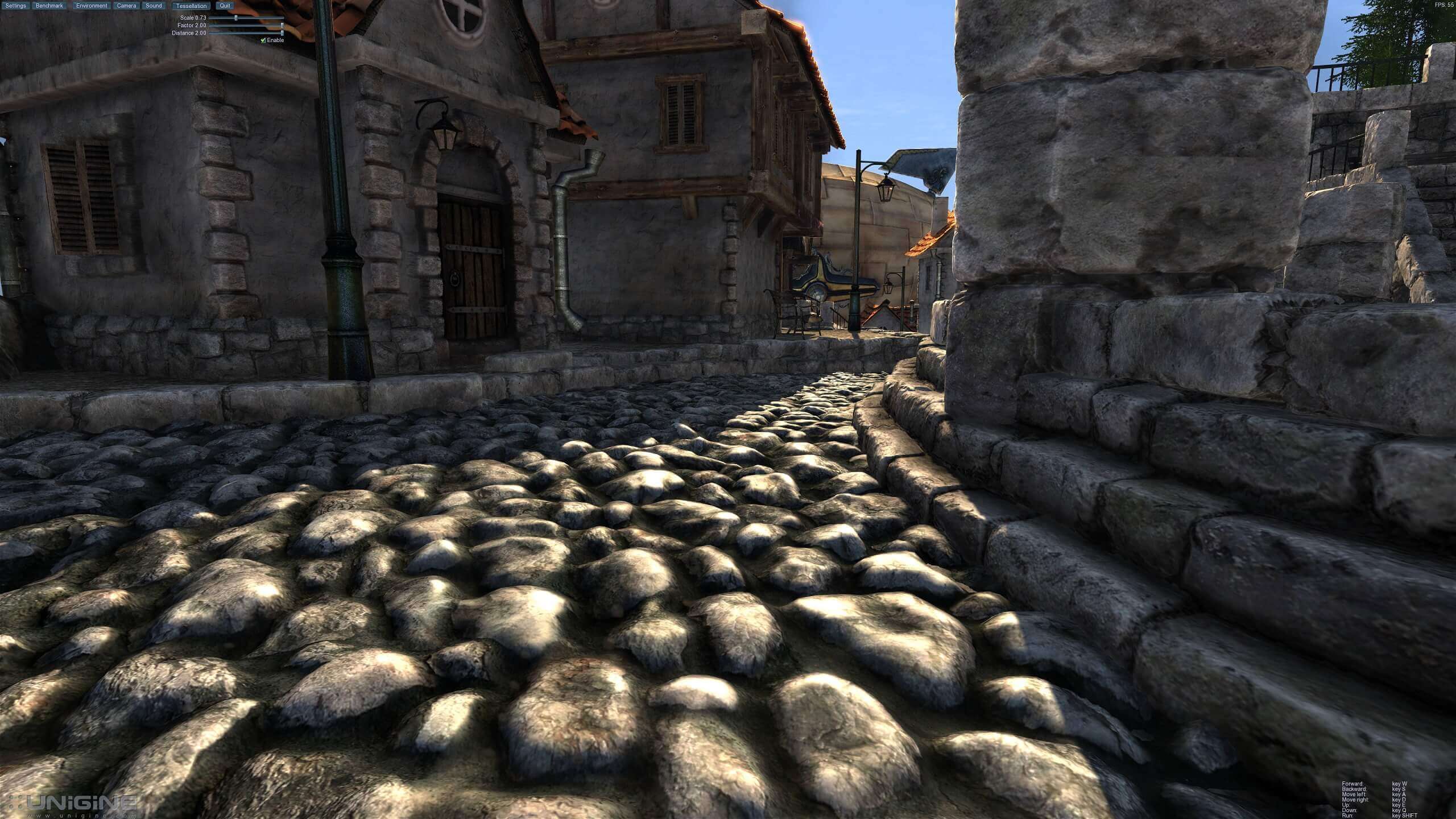
The land, the edges of the buildings and the door look much more realistic. We can see how this was achieved by starting the process again, but this time with the selection of all the primitives (i.e. in wireframe mode):
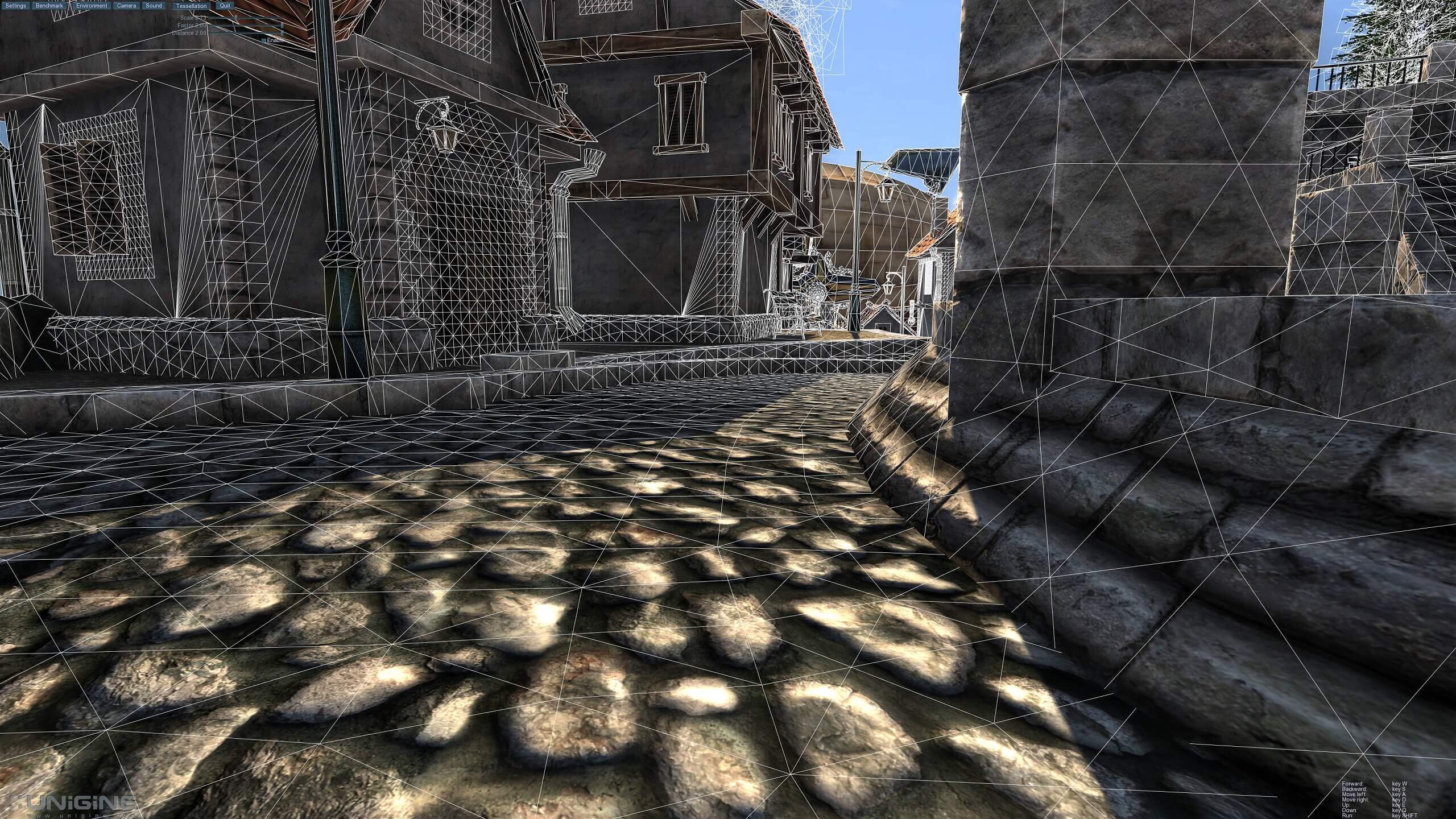
It is clearly seen why the earth looks so strange - it is completely flat! The door merges with the walls, and the edges of the building are simple parallelepipeds.
In Direct3D, primitives can be divided into a group of smaller parts (this process is called a sub-division) by performing a three-step process. First, programmers write a surface shader (hull shader) - in fact, this code creates a structure called a geometry patch . You can think of it as a map telling the processor where new points and lines will appear inside the initial primitive.
Then, the tessellator block inside the GPU applies this patch to the primitive. At the end, a domain shader is executed that calculates the positions of all new vertices. If necessary, this data can be transferred back to the vertex buffer so that lighting calculations can be re-performed, but this time with better results.
What does it look like? Let's launch the wireframe version of the tessellated scene:
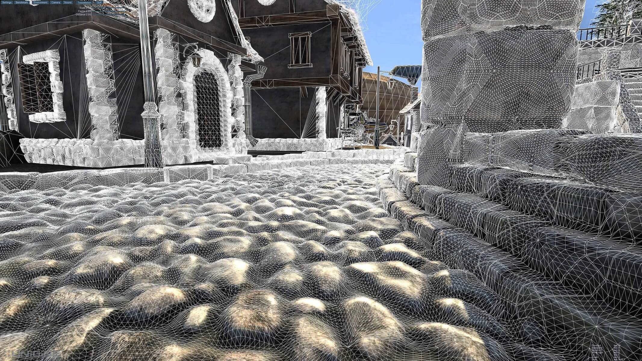
Honestly, we set a rather high degree of tessellation to make the explanation of the process more visible. No matter how good the modern graphics chips are, this should not be done in every scene - look, for example, at the lamp next to the door.
In images with wireframe disabled, you would hardly find differences at this distance, and we see that such a level of tessellation added so many triangles that it is difficult to separate them from each other. However, when used correctly, this vertex processing function can create fantastic visual effects, especially when simulating soft body collisions.
Let's see how it might look in terms of Direct3D code; for this we use an example from another great website, RasterTek .
Here is a simple green triangle tessellated into many tiny triangles ...
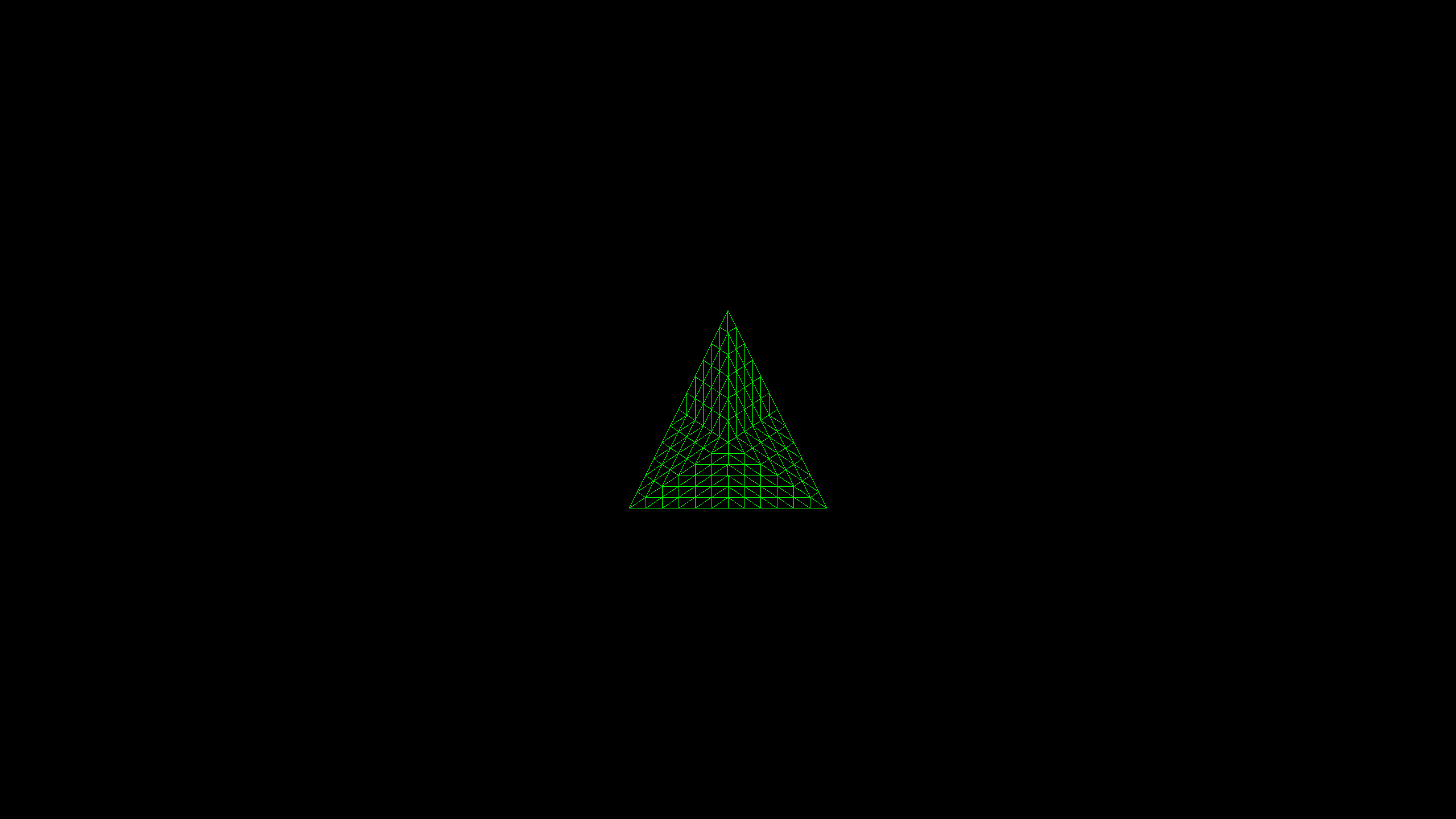
Vertex processing is performed by three separate shaders (see the code example ): a vertex shader preparing a triangle for tessellation, a surface shader generating a patch, and a domain shader processing new vertices. The result is clear enough, but the Unigine example demonstrates both the potential benefits and the dangers of the widespread use of tessellation.
"Iron" can not stand it!
Remember, we said that vertex shaders always process every single vertex in a scene? It is easy to understand that tessellation can be a serious problem here. And there are many visual effects where you need to process different versions of one primitive, but without creating them from the very beginning, for example, hair, fur, grass and particles of explosions.
Fortunately, especially for such things, there is another shader - a geometric shader . This is a more limited version of the vertex shader, but it can be applied to the whole primitive. In combination with tessellation, it gives programmers increased control over large vertex groups.

UL Benchmark's 3DMark Vantage - geometric shaders handle particles and flags
Direct3D, like all modern graphics APIs, allows you to perform a lot of calculations with vertices. Finished data can either be transferred to the next stage of the rendering process ( rasterization ), or returned to the memory pool for reprocessing or reading by the central processor for other purposes. As the Microsoft documentation on Direct3D says, this can be implemented as a data stream:
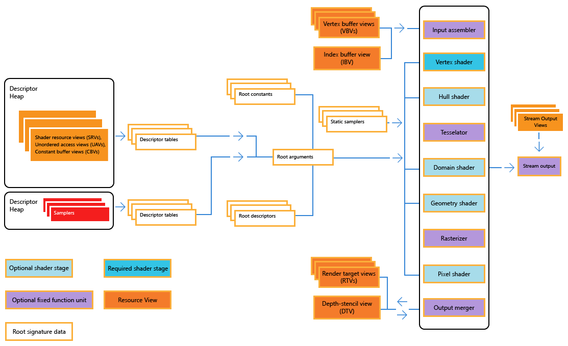
The stream output step is optional, especially because it can only transfer entire primitives (rather than individual vertices) back to the rendering cycle, but it is useful for effects requiring a large number of particles. The same trick can be performed using a variable or dynamic vertex buffer, but it is better to keep the input data buffers unchanged, because when you open them for change, performance decreases.
Vertex processing is a critical part of rendering, because it determines what the scene will look like from a camera perspective.In modern games, millions of triangles can be used to build worlds, and each of these vertices is somehow transformed and illuminated.
Triangles. There are millions of them.
Processing all these calculations and math may seem like a logistical nightmare, but the graphics processors (GPUs) and APIs are designed with all this in mind - imagine a perfectly working factory passing one product at a time through the production pipeline.
Experienced 3D game rendering programmers have fundamental knowledge in mathematics and physics; they use all possible tricks and tools to optimize operations, compressing the vertex processing stage to just a few milliseconds. But this is only the very beginning of building a 3D frame - the next stage is the rasterization, then the extremely complex processing of pixels and textures, and only then the image gets on the monitor.