Introduction
I think every house has a washing machine. Usually it is connected to the water supply via a flexible hose. But a big nuisance can happen with a hose: sometimes they burst, which will lead to a flood both in your apartment and in your neighbors. Therefore, washing machines are connected to the water supply through a special faucet, which must be opened before washing and closed after. I don’t know about you, but I have this crane in an extremely inconvenient place. Yes, and I prefer to start the wash before going to work, so that most of the day the hose is under pressure and can burst at a time when I am not at home. It would be great if the crane opens and closes itself at the right time!
The idea seemed to me quite capable and I decided to implement it: on microcontrollers and with a motorized valve.
To begin with, I formulated the requirements for the developed system:
- monitoring the state of the washing machine: open water at the beginning of washing and close at the end;
- the ability to manually control the valve;
- battery operation and closing the valve in case of battery discharge;
- presence of a leakage sensor: close the valve in case leakage is detected.
Then he figured out what parts it will consist of: a monitor that is installed in the washing machine and a controller that receives signals from the monitor and controls a motorized valve. Communication between the monitor and the controller is via a one-way radio channel.
It seems that this is enough for the technical task. Let's get started!
MCU selection
Since the whole system consists of two devices, there should be two microcontrollers. I scrapped through the guts and found two Atmega8: one in the DIP package, and the other in TQFP. The one in DIP - went to the monitor, and TQFP - to the controller. Later it turned out that the overgrown controller firmware no longer fits in 8KB of Atmega8, so I had to upgrade to Atmega328 - a complete analogue, but now there is four times more memory for the program.
By the way, one of my motives for doing such projects is the disposal of electronic trash, which I have accumulated over many years. True, at the end of the project, trash does not become smaller. It gets even bigger!
Part one. Monitor
Interaction with a washing machine
The first problem: how to determine what the washing machine is doing now? At the beginning of the project, this part of the task seemed very simple to me. All that had to be done was to determine the moments of the beginning and end of washing. On the front panel of the machine there is an LED that lights up and goes out just when needed. I expected to solder a GPIO to it with the foot of the microcontroller, so for the time of debugging, I simply emulated the necessary events on the monitor with the button. I pressed the button - the LED lit up, the washing started. Let go - the opposite is true. However, after parsing the washing machine, it turned out that this LED is part of the dynamic display, and, alas, it is not so easy to determine whether it is on or off.
Turning the control panel in my hands (a couple of days), I found that it was implemented on a PIC controller. Moreover, it is connected to the main board with legs responding to the hardware I2C. Yeah, I thought, you can sniff the I2C bus and thus determine what to do the washing machine now. I found the I2C sniffer code for Atmega on the Internet. Of course, I had to play something.
Frankly: I couldn’t make out the protocol completely (and I didn’t try it too much), but I managed to determine the patterns for the start and end of washing (as well as turning the power on and off) quite accurately. It took me about a week.
Model: Candy GC4 1072 D. The computer periodically sends a series of five byte sequences to the display unit. The first four sequences are in the format:
12 A7 00 – NN – X0 X1 X2 X3 X4 X5 X6 X7 – CS
where: 12 A7 00 - header, NN - sequence number, X [0..7] - 8 bytes of data, CS - checksum. The fifth sequence is some kind of garbage of variable size, the essence of which for me has remained a mystery.
I managed to solve the following patterns:
Power on
12 A7 00 – 01 – X0 X1 X2 X3 X4 X5 X6 X7 – CS
12 A7 00 – 02 – X0 X1 X2 X3 X4 X5 X6 X7 – CS
where X [0..7] at least one is not equal to 0
START
12 A7 00 – 03 – X0 X1 X2 X3 01 01 01 01 – CS
where X [0..3] is any number
STOP
12 A7 00 – 03 – X0 X1 X2 X3 00 00 00 00 – CS
where X [0..3] is any number
It can be seen that these are not strict sequences, namely templates, so I had to tinker with the parser.
The logic of work is approximately the following: if we get the POWER ON sequence, but there is no START, then we start broadcasting packets with the status 0. If the START sequence appears, change the status to 1. In other cases, there is nothing to send the helmet.
We will talk about packages and what status is next.
It's funny, but when I spied on I2C packets, I did not have the opportunity to connect to the sniffer computer. I used for this Raspberry Pi c powerbank'om, which had an aluminum case. So, as soon as this building came into contact with the body of the washer, an RCD was pulled out in the shield, the lights went out in the apartment and I started looking for the flashlight with the matyuki. :) Why such garbage happened - still remains a mystery to me.
Radio channel
Initially, I did not want the extra wires coming from the washing machine. That is, the connection was supposed to be wireless. From here, there were three possible solutions to the problem: WiFi, Bluetooth and the RF module for Arduino. I settled on the latter by choosing the FS1000A module.
Of course, on Habré there will be many people who reproach me with this choice. They will hint that on Ali-Express it is possible to purchase an ESP module with full WiFi for inexpensive. But I thought that this would greatly complicate the project, and decided to act simpler.
As you know, the FS1000A RF module cannot be connected directly to the RS232 interface: a long sequence of zeros or ones breaks the receiver synchronization. VirtualWire library is designed to solve this problem. However, this library is written for Arduino, and I program exclusively natively for Atmega in C. Fortunately, the code for Arduino is very similar to pure C, and with minor modifications, the library was successfully ported.
There were some difficulties: at first, the packages did not want to reach the receiver. I blamed my crooked hands for everything, but by directly connecting the terminals of the receiver and transmitter controllers, I was convinced that everything works in the software part. The transmitter ordered from China turned out to be faulty. I had to buy another kit. Then I fixed the old one and now I have two sets of transmitter-receiver. Remember what I wrote about reducing trash?
The data has been sent, but what exactly is contained in this data? Here is what the transmitted packet is:
typedef struct { uint32_t dst; uint32_t src; #define WMP_MSG_STATUS_ALIVE _BV(0) #define WMP_MSG_STATUS_VALVE _BV(1) uint8_t status; } wmp_msg_t; #define WMP_ADDR_MONITOR 0x4d504d57 #define WMP_ADDR_CONTROLLER 0x43504d57
The first two double words are the physical addresses of the receiver and transmitter. In my case, they are strictly fixed: 0x43504d57 - receiver (controller) and 0x4d504d57 - transmitter (monitor). In fact, the first 8 bytes are this packet signature. Significant information is found only in the last byte - the bit flag. The set zero bit of this flag means that the monitor is on and working - it should always be 1. The first bit is the status of the valve: 0 - the valve must be closed, 1 - open. Everything.
It is assumed that the monitor must periodically send packets to the controller, confirming its operation and the serviceability of the data channel. In case of loss of the communication channel, the controller must emergency close the valve.
VirtualWire library monitors the integrity of the transmitted data using CRC32. I did not have to make additional efforts in this direction. The beauty!
Design
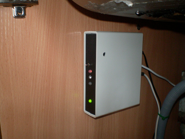
Structurally, the monitor is made in the form of a small board, which is glued on the hot glue "uncle Liao snot" inside the front panel of the washing machine. The board connects the connectors to the gap between the computer and the display board. The machine itself has not undergone any modification: at any time it can be brought to its original state.
Part two. Controller.
Radio channel
Everything is simple here: there is a receiver of the FS1000A kit and the receiving part of the VirtualWire library. The package is parsed and its status is transmitted to the output. VirtualWire receiver occupies TIMER1 in the microcontroller.
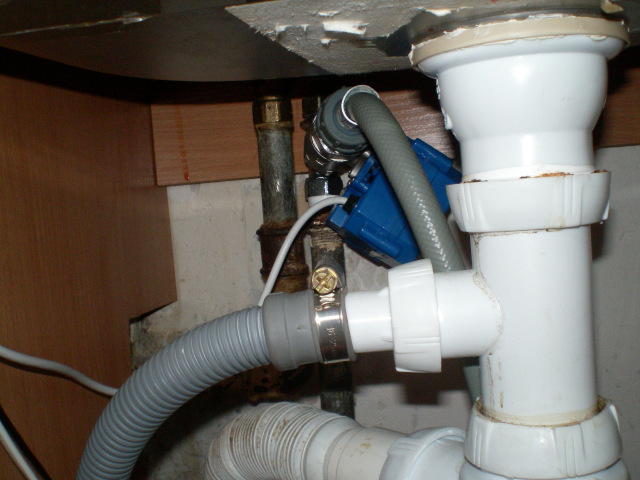
Valve control
In the Chinese online store, a 3/4 ”motorized valve was selected, powered by 5 volts, and with terminal sensors connected to the cable. This valve was installed between the ball valve and the hose of the washing machine. To control the valve, on the same Chinese site, a low-power stepper motor driver was ordered on the L9110 drivers. I connected it to the controller as follows:
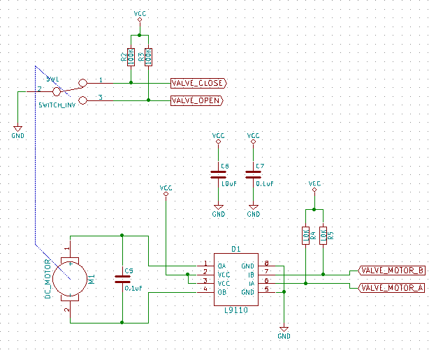
From the software point of view, there were no particular difficulties: by the inputs VALVE_CLOSE and VALVE_OPEN we determine the current status of the valve. If this status needs to be changed, turn on the motor for opening or closing and wait until a logical 0 is established at the corresponding input. However, since opening or closing takes some time, I would like not to lose control over everything at that moment device. Therefore, on the Atmega timer, a primitive scheduler was built and control of the valve was transferred to a special task. At the same time, the special WatchDog software module measures the time it takes for the valve to switch, and if it is too long, a signal about its malfunction is generated. Later, other interesting things were hung on this scheduler, such as flashing LEDs and polling the leakage sensor. But more on that later.
Also, a three-color status LED and a three-position manual control toggle switch belong to the valve control circuit. In the middle position of the toggle switch, automatic control is activated according to the signals from the washing machine and other sensors. In the event of a valve malfunction, the red and green colors alternately light up.
LED and sound indication
With LEDs, everything is simple: they cling directly to the I / O ports via limiting resistors. The currents there are not large, and the ports on Atmega are quite powerful.
But the sound had to tinker. Firstly, I did not find a large and loud piezo emitter. It seems that such people exist in nature, but as soon as I attended to the purchase, it turned out that the choice was not even great at all. The coolest thing I managed to get sounded very quiet. I had to surf the Internet for recipes.
I settled on a circuit with one transistor and an autotransformer, which swings the sound voltage from 5V to 50V. And then it turned out relatively loudly. Not at all frequencies, of course, but closer to resonance.
It was only during the generation of the sound that the brightness of the LEDs slightly decreased (a jamb with power), but the microcontroller did not freeze and the control program did not break. I thought that this is a feature of the debug layout and everything will work fine on the final board. I was mistaken - it didn’t get better. Worse, however, too.
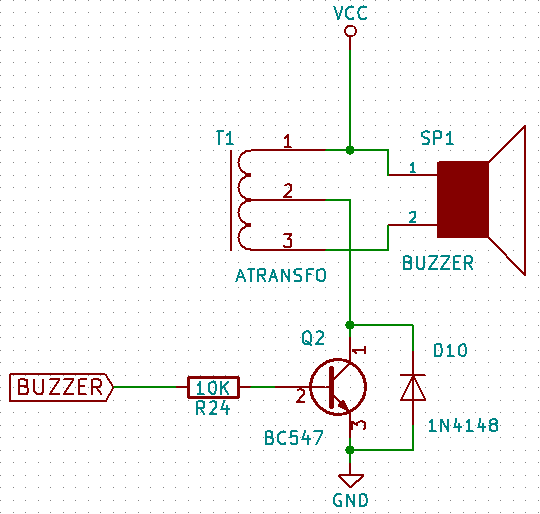
Another problem was that I ran out of timers and in the background I could not generate sound. I had to ask the squeak period with sleeps. So, during the generation of sound Atmega can do nothing but interruptions, too, had to be disabled, otherwise the tone is not clear. But this turned out to be not very scary since the sound output did not intersect with other critical tasks, such as controlling a valve or receiving data via radio.
Further, I selected the sleep constants so that they corresponded to the notes and came up with several more or less harmonious combinations: “the valve is open”, “the valve is closed”, “washing is finished” and “leakage”. I’ll tell you separately about the “wash finished” signal later.
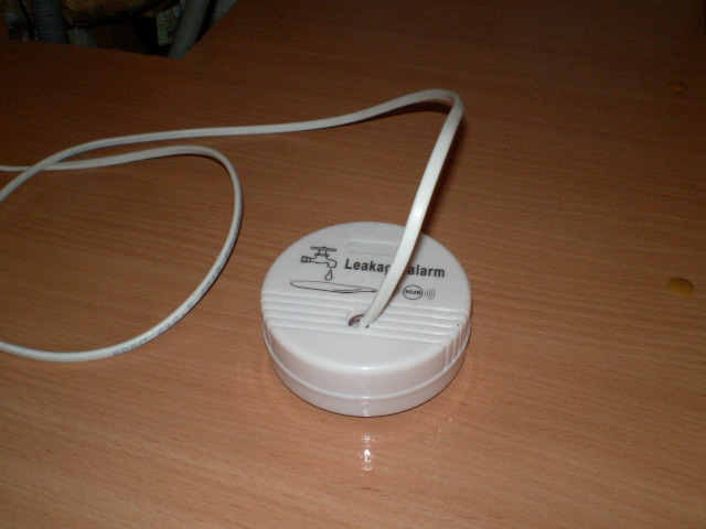
Leak detector
The leak detector was originally planned to be done on the built-in ADC of the microcontroller. Experiments have shown that this is a perfectly working solution. However, I have met that sometimes a capacitor is added to the sensor with contacts so that it is connected and if there is no break in the wire somewhere. You can check the presence of a capacitor (and measure its capacitance) using: RC chain, comparator and clock. As a comparator, a conventional GPIO input is used (it is also a logical input and switches from 0 to 1 at a certain voltage), and there are enough hours in the microcontroller.
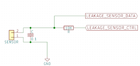
It was assumed that from time to time I would check the presence of a capacitor on the line, and then use the ADC to determine if the sensor contacts are in the water. As it turned out, it is enough to measure only the capacitance of the capacitor: if you lower it in water, then the charge time will increase, and the discharge will decrease. Moreover, the time will change by a sufficient amount so that it can be confidently detected.
For my system, I chose to measure the charge time: if the capacitor is not connected, then it is zero, if it is dry it is relatively small, and if it is in water, then the charge time is much longer. The exact values were determined using a saucer with water and a series of experiments.
The leak detector has its own red indicator LED. If the sensor is not detected, it lights up and the command to close the valve is transmitted to the air. One has only to restore communication with the sensor, the LED goes off and the valve can be opened (if only the machine is in the washing state, of course). Another thing is if the sensor detects water. In this case, the indicator starts flashing, a nasty intermittent sound is heard, and the valve is forcibly closed. But most importantly, the controller never leaves this state. A leak is considered a serious accident, and the water supply will not resume until you forcefully restart the device.
Food
Food is the most incomprehensible part for me in this project. If I am a little versed in digital circuitry, then in analog, to put it mildly - not really. But, thanks to the Chinese: I can purchase ready-made modules for DC-DC converters with battery charge controllers, and based on them I can think of something workable.
From the very beginning, it was planned to make the device self-powered, so that in case of a power outage, be sure that the water will be shut off. In addition, I had a 9V power supply, which was required to be attached somewhere. In total, the introductory result was as follows:
- 9V comes from the network;
- 3.4 ~ 3.7V comes from the battery;
- to charge the battery you need 5V;
- 5V is needed to power logic and power circuits;
- if the mains voltage fails, switch the power to the battery;
- the battery charge signal, the voltage on the battery and the mains operation signal must be transmitted to the controller
The block diagram turned out as in the figure.
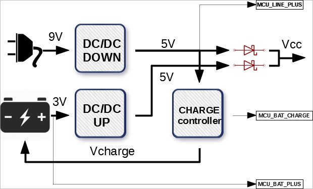
Two Schottky diodes are used as a switching element. The charge controller has two LEDs: CHARGE and STANDBY. The signal from the first was connected to the GPIO port of the controller so that the monitor could know that the battery was charging. Also, a signal from the first DC-DC converter is applied to the microcontroller port to determine if the device is operating on a mains or battery. To control the charge level, the voltage from the battery is supplied to the ADC of the controller. If the voltage is too low, the monitor closes the valve and goes into standby mode: it does not respond to any commands until the voltage in the network appears.
Unfortunately, there were some jambs here: for some reason, the valve motor takes part of the energy from the battery. Apparently, I made a mistake with the power of the network DC / DC converter or with the thickness of the power tracks on the board. As a result: after opening or closing the valve, the battery starts to charge.
To monitor the power status, there is a special two-color LED. If it is green, then the device is operating on the network. If red - then from the battery. If it is green, but the red color is blinking, then the battery is charging.
Work logic
Well, we have all the hardware and their software support, now we need to somehow make all this interact with each other. Initially, I saw the implementation of the logic of work in the form of a large loop (what is called the main loop) with a bunch of ifs inside.
In the process, there was a need for a task scheduler for such simple actions as: blinking an LED, polling a leakage sensor, tracking the valve switching time and power control, which I posted on TIMER0. The scheduler itself did not run the functions associated with the task, but only set the synchronization bit to a unit in the descriptor associated with the task. The task was still carried out in the main cycle; we managed to get rid of tracking time intervals, which made it very simple.
From the zoo ifs, which check the status of various subsystems of the controller and make a decision: it was necessary to refuse to open or close the valve. It’s very difficult to debug this and it’s very easy to get confused. Instead, I liked the idea from D. Hazerman’s ancient book: "How to make a robot yourself." The book suggested that each module generate its own control signals: forward, backward, rotation, etc. Further, only one that comes from a block with a higher priority is selected from these signals. I did about the same.
I prioritized the blocks as follows:
- Leak block
- Battery Control Unit
- Manual valve control unit
- Radio control valve control unit
- Valve timer WatchDog block
Each block generates three commands: UNDEFINED, OPEN and CLOSE.
The leak block has the highest priority, but it does not have the OPEN command, but its CLOSE command definitely closes the valve, no matter what other blocks say. The manual control unit can interrupt any signal of the radio channel unit, which allows you to control the valve regardless of what the washing machine indicates to us. Well and so on. That is, a logical hierarchical structure has appeared that is easy to understand and debug.
Now, let's get back to the signal: "wash is finished." Alas, my model of a washing machine does not have the opportunity to inform about the end of its work with the help of sound: Candy engineers did not provide such an opportunity. On the other hand, I have an additional device that has a piezo emitter and at every moment of time knows what the washing machine is doing. Why not make him report the end of the wash? Well, let's make the controller squeak loudly (at the resonance frequency) when the valve closes signal. Add another five-minute guard interval so as not to listen to this squeak every time you turn the machine on and off. The valve is open for five minutes - the washing has definitely begun.
results
Development took me about a year of unhurried (very unhurried) work. The device has been working for two years now. In operation, it proved to be quite satisfactory. But not without flaws. Let's list them honestly:
- I messed up something with the power: the valve motor takes part of the energy from the battery.
- The sound generation circuit draws the supply voltage. You can clearly see how the LEDs change brightness when sound is played.
- The radio channel is not very stable. Firstly, the signal disappears if a person stands close to the washing machine. And secondly, sometimes the signal worsens on its own. In this case, you have to use the manual toggle switch, but this happens extremely rarely.
- The monitor unit in the washing machine hung a couple of times. The controller block did not freeze even once.
- The sound from the piezo emitter was very drowned out inside the case. I drilled a hole in the koprus: it got better, but not really. I had to solder the emitter from the board and stick it to the case, directly opposite the hole.
In general, I consider the development successful and very useful. I start the machine in the morning and calmly leave for work: I know that at the right time the water supply tap will be turned off.
Archive with project files can be downloaded here .
A few pictures.
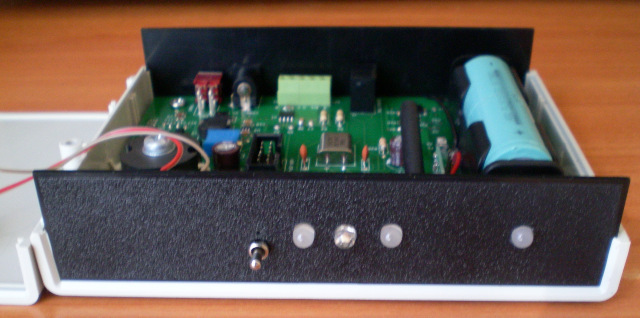
Top view with top cover removed 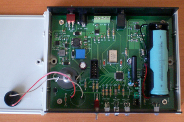
Rear view, from the side of the connectors 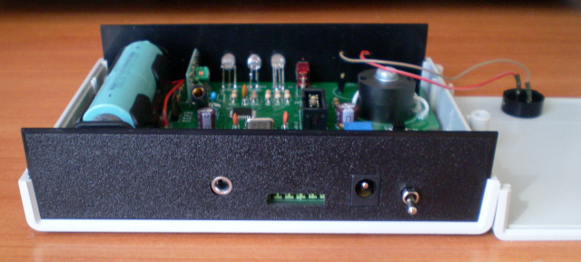
- «»