The article describes a sensor that allows you to detect the presence of an Ethernet signal in the cable path without contact, setting it above any UTP RJ45 connector. The point is to know 100% that the Ethernet connection is carried out precisely on this particular cable path SCS.
In fact, the existing NMS (Network Managment System) knows about the corporate network and more, except for the cable component of the network. About which they in 95% of cases do not know anything.
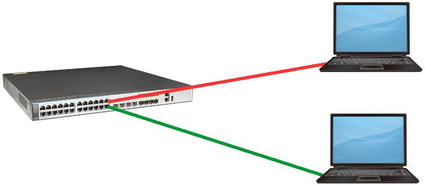
Take a corporate switch with the most sophisticated control system, connect two laptops to it using a regular red and green UTP patch cord, and try remotely without eye contact to understand which cord each laptop is connected to. It seems to me that this problem can only be solved with the help of our sensor.
In this task, the patch cord is a model of the cable path of the corporate structured cable system (SCS) degenerated to primitiveness, and the real path is much more complicated.
An inquisitive reader may notice that in the world there are already many options for tracking SCS switching (but they will not solve the problem with red and green cords) called smart SCS. This is true, but they are all very expensive. Our task is to reduce the price of intellectual SCS at times, in fact, at times. Due to what? Due to the Russian innovative technology.
Firstly, almost all existing intelligent SCS work according to the cross-connect scheme, two smart patch panels are required for switching. Here's what the path looks like in a cross-connect scheme:
- half of the patch cord, embroidered on one side on the patch panel, on the other plugged into the switch;
- patch panel port;
- patch cord, usually custom and expensive;
- permanent link to the workplace (includes the port of another patch panel, cable, outlet at the workplace);
- patch cord to the computer in the workplace.
Our intelligent patch panel, perhaps the only one in the world, can work according to the interconnect scheme:
- patch cord regular and standard;
- permanent link to the workplace;
- patch cord to the computer in the workplace.
As a result, money is simply saved on excess equipment, and it takes up less space in a telecommunication rack.
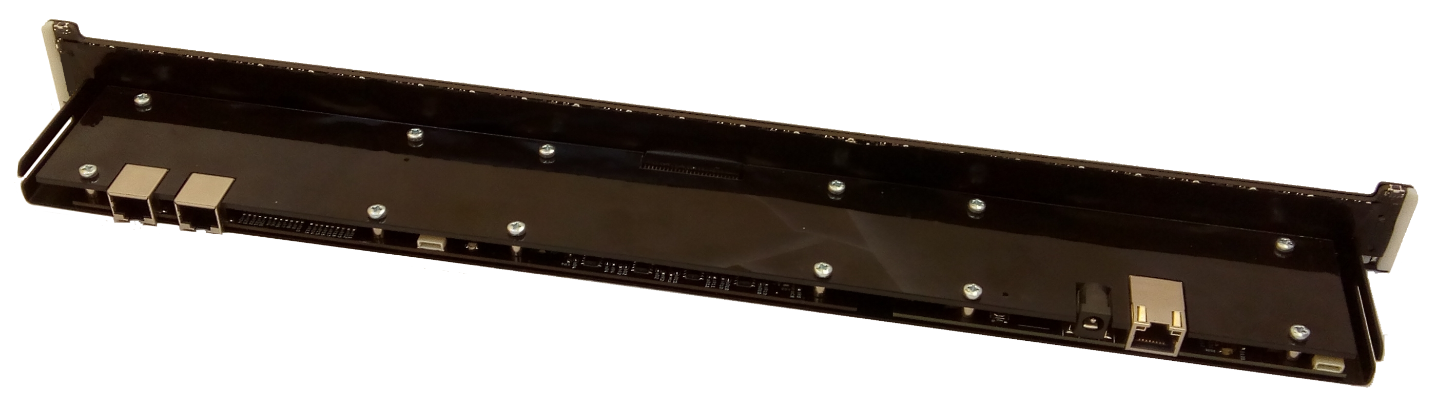
Secondly, there is no electromechanics in our sensor. It is purely electronic, assembled on serial electronic components suitable for contract manufacturing. People who are involved in the development of electronics will confirm that the presence of a large number of complex connectors in the product carries the cost of the product into space. By the way, the most expensive part of the electronic part of our patch panel is a regular RJ45 connector, which we use to transmit the results of the sensors (we have two of them).
How does such a sensor work?
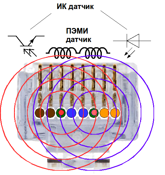
The sensor is mounted above any UTP RJ45 plug and has two sensors. An IR sensor based on an IR diode and a phototransistor simply detects the presence of a connector (or finger) near the sensor. This is not what I came up with; competitors use it widely. Another sensor is more interesting.
It should be noted an important feature in this context of any RJ45 plug. The cores of the cable of one of the pairs (usually green, sometimes orange) are separated by the cores of a blue pair. This split pair is marked with red circles in the figure. Strictly above the veins of this pair are miniature 1x1x2 mm inductors. When a current of Ethernet signals flows through a divided core, an alternating electromagnetic field is created around the wires, which induces EMF in the coils. The coils are turned on “towards” each other, that is, the EMF from the differential Ethernet signal is summed there, and the common-mode EMF from the interference is subtracted. The EMF is small, tenths of a millivolt, but sufficient for amplification with the help of an op-amp and processing by a microprocessor.
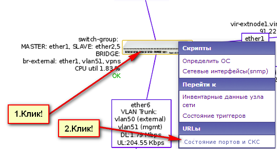
That is, we can track the appearance (disappearance) of the Ethernet signal in the cable to the accuracy of a millisecond (more precisely, but not needed). This time coincides with the time of raising (lowering) the port on the switch. Comparing these two times, you can understand in which port of the switch the cable path is connected on which the sensor is mounted. The problem of red and green patch cords is solved. And the problem is solved for the intellectual SCS as a whole.
In my opinion, this is enough, but perfectionists can note that if there is no Ethernet connection, the sensor does not work. And they will be right in their own way. You can use FLP signals to get closer to perfection. If there is no Ethernet connection, then in accordance with the Ethernet standard, the switch port transmits autonegotiation signals Even on an open line, when nothing is connected to the SCS outlet at the workplace, a PEMI (side electromagnetic radiation) from the FLP signal current arises near the RJ45 plug. From the point of view of the mathematical apparatus of electrical engineering, the current is called imaginary. But it really is, you only need the cable length after the sensor (permanent link) to exceed 3 meters. Coils of imaginary current are also monitored, but the electronics for signal processing cost a little more.
As we remember, the switch port does not transmit Ethernet signals. Therefore, it can do a shutdown without consequences, FLP signals will not be transmitted, and simultaneously with shutdown (and then with no shutdown), the coil sensor will change its state. Again we compare events on the switch and the sensor.
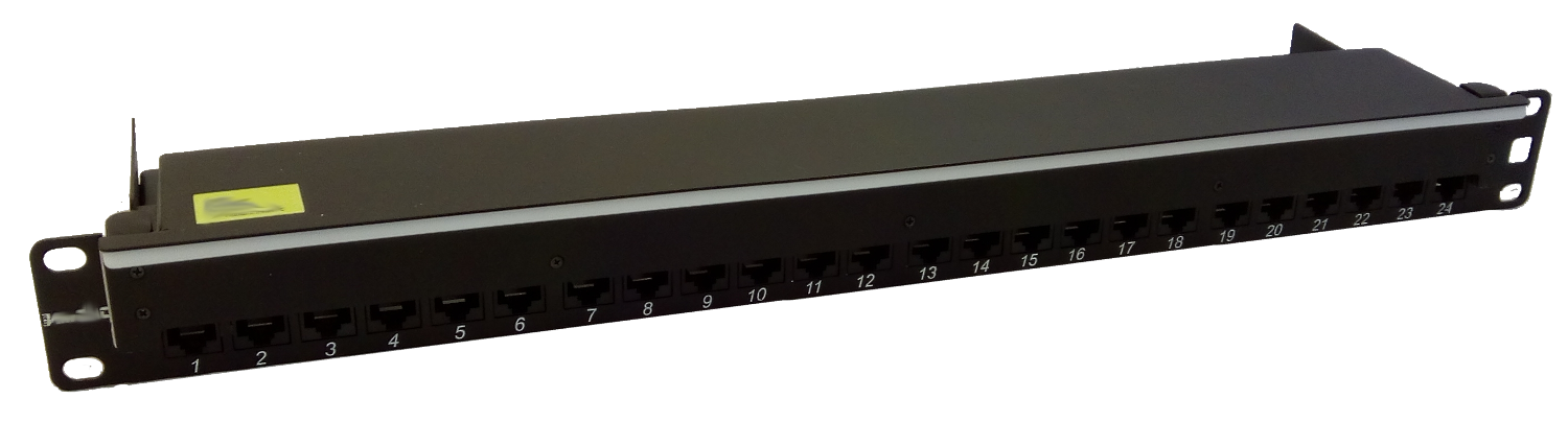
The system is implemented like this. There is a chassis, no electronics, only painted steel, where you can insert Keystone UTP modules of any manufacturer.
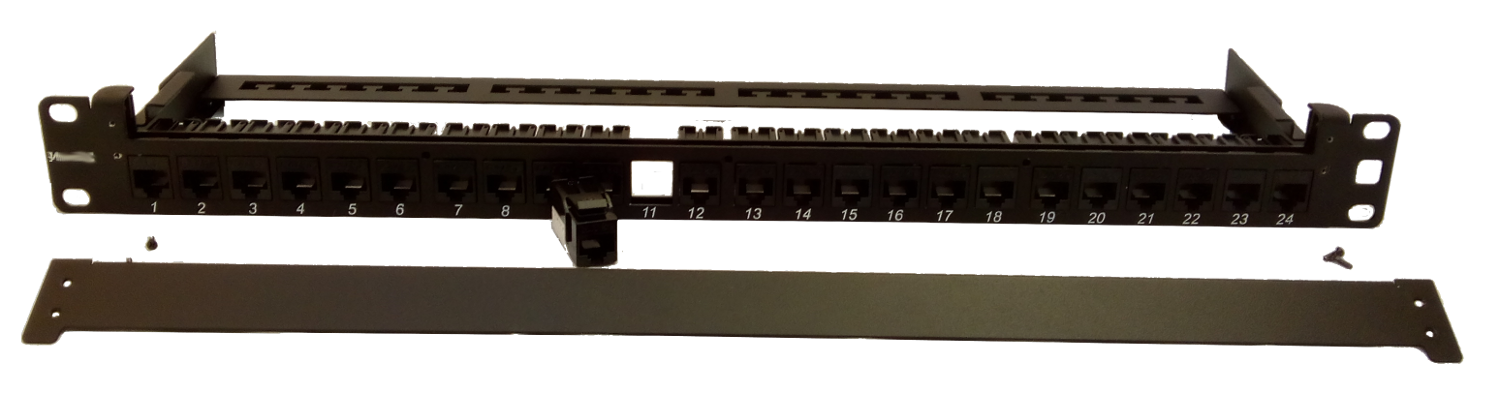
There is a niche in the chassis for installing a sensor system, which can be closed with a plug. That is, for starters, you can install a regular panel, and then make it intelligent at any time without interruption in the network. The cable connection card can then be restored automatically. It is clear that for this you need to buy a sensor board.
And the panel will become intelligent.
Answers to potential questions:
With shielded SCS does not work. Shielded cable is possible, but the RJ45 plug and Keystone are unshielded. In my opinion, reasonable. If your attacker can penetrate the server room, then the shielded patch cord does not save.
It also does not work with optics. Most likely, you can make an analog for optics. Sensors for night vision devices (and sights) are developing very quickly. They can already catch pico-watts. By installing a similar sensor on the outer surface of the optical core, we can in principle understand whether there is a useful signal. But in the data center they are now switching to multi-core optical connectors, where the cable connection card becomes clear there. And in the server side, tracking 2-3 uplink seems pointless.
With the help of coils, it is impossible to remove data in the cable. The sensor is very narrow-band (~ 10 MHz resonance), and the Ethernet signal is very broad-band.
The price of the port in such systems is not accepted to publish, piece goods. Compared to competitors, it comes out very, very inexpensive.
About software. There is software that writes SCS events in Postgres. His software, which paints colorful pictures, no. On the one hand, in NMS, using primitive scripts, you can simply show the cable connection table of a particular switch when you click on the switch, and you can simply integrate the mentioned database with Helpdesk, avoiding considerable expenses for drawing floor cable routes.
On the other hand, it can be integrated into third-party programs for graphical visualization of physical infrastructure with the drawing of cable routes. On the third hand, the Ministry of Construction promises that in Moscow in 2020, all newly designed buildings will be with BIM (Building Information Model), where the SCS will be straight in three-dimensional form. In the future, perhaps, we need to integrate there.
Is this necessary in principle? Someone yes, someone no. Moreover, the answer may change over time. But the inexpensive chassis of the patch panel with a slot for sensors allows you to postpone the solution to a better time, and then quickly and efficiently solve it when these times come.
If you missed something, please ask.
PS Philosophical retreat. At the moment, of all levels of OSI, the SCS computer network is the only one that is not automatically controlled. Without control, manual or automatic, SCS will slide into chaos according to the second law of thermodynamics. If you have an order (and rightly so) with patch cords, then you somehow spend resources on this.
PSS In the comments they write that it is easier to get the admin to keep a log of cable connections. You can make it, well then you still need an auditor who will periodically check the accuracy of the cable journal entries. I wonder how he will do it.
PSSS In the comments, there is strong confidence that by reading the mac address on the switch port you can get information about SCS. All normal NMS read mac addresses perfectly, and I personally have not seen NMS that featured patch panels with connection cards. Maybe NMS manufacturers just don’t realize that SCS is very easy to integrate there?