To the question of VNA or Japanese-Chinese device
“And so it was possible?”

In an extreme post, Jack Hansley mentioned a device recently appeared on the Internet called NanoVNA, or a small-sized portable vector network analyzer (VAC) in the range of 50 kHz-900 MHz with a cost of $ 50.
“Fifty dollars, Carl!”
As Jack wrote, there is no reason NOT to buy such a device at such a price, and I completely agree with him. It’s not that I constantly worked on radio devices, but I ordered this device on Ali and wait until it comes to make sure the parameters. The lucky ones who have already managed to acquire it are usually satisfied, although there are nuances. If you believe the information, then it was developed quite a long time ago (three years ago) by a certain Japanese, and laid out the source code on Git, and this year the Chinese abruptly began to duplicate and sell it (the device, of course, not Japanese).
Those in the topic immediately understood what was happening, for the rest I’ll explain that the price of the VAC starts from $ 3 thousand, and no one knows except R&S where it ends. You can buy a relatively inexpensive VAC with a dynamic range of 120dB and a frequency of up to 1500MHz for 176,000 rubles, and this is a characteristic figure. Therefore, many will understand my reluctance to wait for the device to arrive, and immediately understand how it is arranged and why it works, especially since all the sources are open.
I go to the developer's git, look at the circuit and start to get a little stunned.
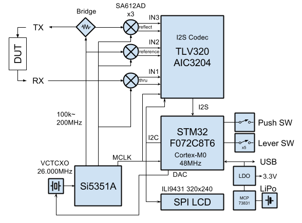
We omit the microcontroller, touch screen and buttons (although there is a funny rocking chair), this is completely uninteresting and ordinary, we look at the meter.
First of all, we observe a programmable generator (without it it is difficult to imagine the VAC) and we observe the well-known (and inexpensive) m / s Si5351A. But after all, her output frequency range is clearly not 900 MHz. I take the date, the way it is, the output frequency is up to 200 MHz, moreover, the output signal is fundamentally direct Coal (this is how we joked in this connection) and there is no sine.
Okay, let's go ahead and see three balanced mixers on m / cx SA612AD (explicit local oscillators). Here the same thing, at one input the permissible frequency is up to 500 MHz, at the second up to 200 MHz, so the 900 MHz range is clearly not stretched.
And then, for some reason, the outputs of the mixers are fed to the inputs of the m / c TLV320AIC3204 (audio codec), although the MK contains an ADC that is no worse both in speed and resolution. In general, not a circuit, but continuous misunderstandings, and how IT can provide the claimed frequency range remains a mystery.
I invite readers to think and answer the question.
In principle, there is already enough data, but I (as an honest person) will give two more tips:
- the instrument’s dynamic range is uneven - 70 dB (50 kHz-300 MHz), 60 dB (300 m-600 MHz), 50 dB (600 m-900 MHz),
- On the forum, a radio cat asked someone if it was possible to stretch the range to 1200 and they reasonably (with the spectrogram attached) replied that the seventh harmonic was already too weak.
Spoiler heading
The key point is that the device operates on the harmonics of the square wave of the generator. Naturally, at odd harmonics, since the signal duty cycle is 1/2.
Then, to achieve the fifth harmonic of 900 MHz, the fundamental frequency 900/5 = 180 MHz will be required, quite in the range of the generator and mixers (although the latter is not obvious).
Then, to achieve the fifth harmonic of 900 MHz, the fundamental frequency 900/5 = 180 MHz will be required, quite in the range of the generator and mixers (although the latter is not obvious).
Well, even if this is exactly the way we apply a mixture of frequencies to the device under study, but to obtain a characteristic, we need to separate some frequencies from others and measure them separately, which means we need low-pass, narrow-band, tunable filters after the local oscillator (or band-pass and tunable high-frequency ones him) is not an elementary task, although it is realizable. But there are simply no filters on the circuit, and the few RC circuits that are in the matching circuit cannot perform such a function. And, nevertheless, the device works, how?
I came up with an idea that initially seemed ingenious - we introduce a small detuning into the frequency of the mixer. Then at the first input of the mixer we have f + 3 * f + 5 * f + ..., at the second input f1 (f-Δf) + 3 * f1 + 5 * f1 + ... and at the output we get a mixture of frequencies
(f + 3 * f + 5 * f + ...) * (f1 + 3 * f1 + 5 * f1 + ...) = (f * f1) + (3 * f * f1) + (f * 3 * f1 ) + (3 * f * 3 * f1) + ..., then each product turns into the sum (f ± f1) + (3 * f ± f1) + (f ± 3 * f1) + (3 * f ± 3 * f1 ) ... = (Δf + (2 * f-Δf)) + ((2 * f + Δf) + (4 * f- Δf)) + ((4 * f + Δf) + (2 * f- Δf)) + ( 3 * Δf + 6 * f-3 * Δf) + .... Then, if you put a band-pass filter with a transmission from 0 to Δf with a cut-off of up to 3 * Δf, only the component depending on the first harmonic remains, and all the others are suppressed and can be safely measured. A tunable filter is included in the codec, the only question is its technical capabilities, they should be sufficient.
The idea is really good, it allows using a meander instead of a sinusoid, but it has a big flaw - what to do with higher frequencies (third and fifth harmonics). After all, if you pick up the detuning so that the beats of the third harmonics fall into the filter band, then the beats of the first will get there all the more. I preliminary see three possible solutions:
- Make a filter with an adjustable lower limit, so that Δf falls into the band, but Δf / 2 and Δf * 3/2 do not. The task is not simple, but fundamentally solved with sufficient equipment.
- Make the detuning so that to measure the third harmonic of the signal, the fifth harmonic of the pilot fights with it. Then the filter remains simple, but what to do with the fifth harmonic of the signal is not clear, the third harmonic of the pilot clearly does not reach it.
- Make sequential measurements - first with Δf we measure the beat of the first harmonics, reduce Δf by 3 (2) times and measure the sum of the first and third, similarly for the fifth. Subtract one from the other and get everything you need. Here my knowledge in the field of DSP is not sufficient and I cannot evaluate the practical feasibility of such an option.
Which option is implemented in this device can be determined from a thoughtful study of the capabilities of the codec and analysis of the text of the program, but, in principle, this is not so interesting - possible solutions have been outlined. Personally, I would go for the third, if it is fundamentally feasible, I’ll figure it out later.
PS What kind of people live nearby (in the sense on the same planet) with us.
All Articles