Simple experiments with the STM32F103 microcontroller (Blue Tablet)
Many have acquired a “blue pill” to try. But due to the complexity of programming, this thing turned out to be somewhere on the shelf, until better times.
We will consider that the “best times” have arrived.
What is necessary for experiments:
- Hardware
- Software
Hardware
All used parts / components can be purchased on aliexpress.com
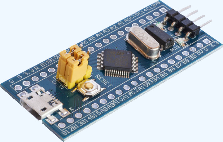
- Of course, first of all the controller itself. "Blue Tablet"
- USB-UART adapter
- Micro usb cable
- a set of wires for connecting components to each other
It is recommended to use the ST-Link V2 programmer for faster, in comparison with UART, loading of “firmware” and debugging of programs
Software
- STM32 Flash loader demonstrator (UM0462)
- STM32 Virtual COM Port Driver (usb vcp)
- STM32 ST-LINK utility
- www.embitz.org Development Environment
- MIOC - program - configurator, creating a firmware template.
- terraterm terminal emulator
What is a module?
A module is a combination of hardware and software. The hardware part is the “tablet” STM32F103C8T6, the software part is the “firmware template” created using the MIOC program . This program is OpenSource .
Microcontroller ports
The microcontroller has pins or legs. Some of them are microcontroller power, some have a special purpose (for example, Reset), some are general-purpose input / output interface (English general-purpose input / output, GPIO).
Ports are grouped (A; B; C ...). Each group contains up to 16 ports, numbered from 0 to 15. As a result, the port numbering looks like PA0, PA1, ...
Ports are used for communication between the components of the module, for example, a microprocessor and various peripheral devices. Ports can act as input, output, and bidirectional.
The “tablet” board is marked with ports.
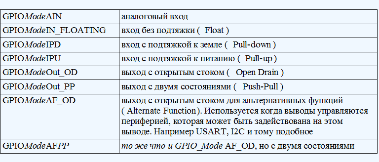
GPIO - General Purpose I / O Interface
In the IO module, the main types of ports are presented in the table:
As sensors, actuators we will use various devices from Arduino.
MIOC (Module Input-Output Configurator) Program
Using this program, we create / configure the firmware template (project for Embitz; Keil) of the IO module. The installer does not require. Download, run. Using this program, we create global variables that we will use in our firmware. Variables can be associated with ports.
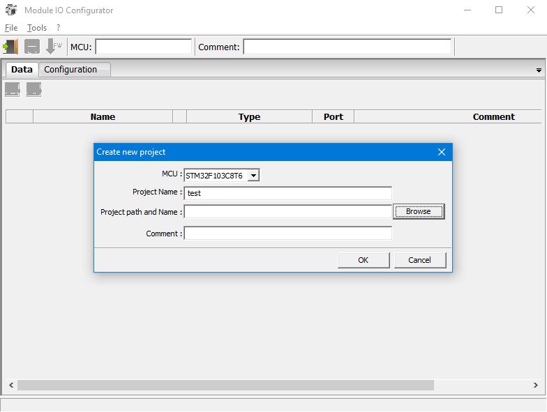
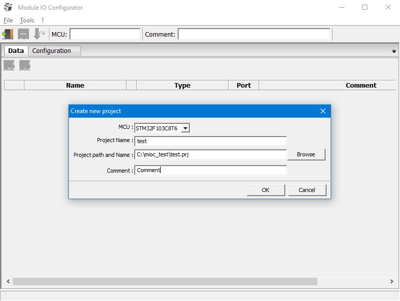
First run window:

Create a project:

Select a folder for the project. Folder, for the project should be empty!

The first program is “hello word” for the microcontroller
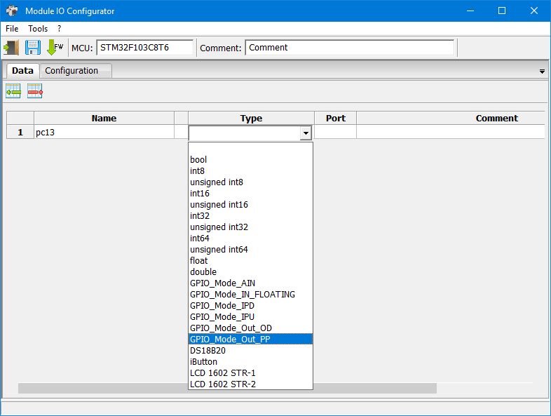
We blink the LED that is on the “blue pill”. This LED is connected to the PC13 port.
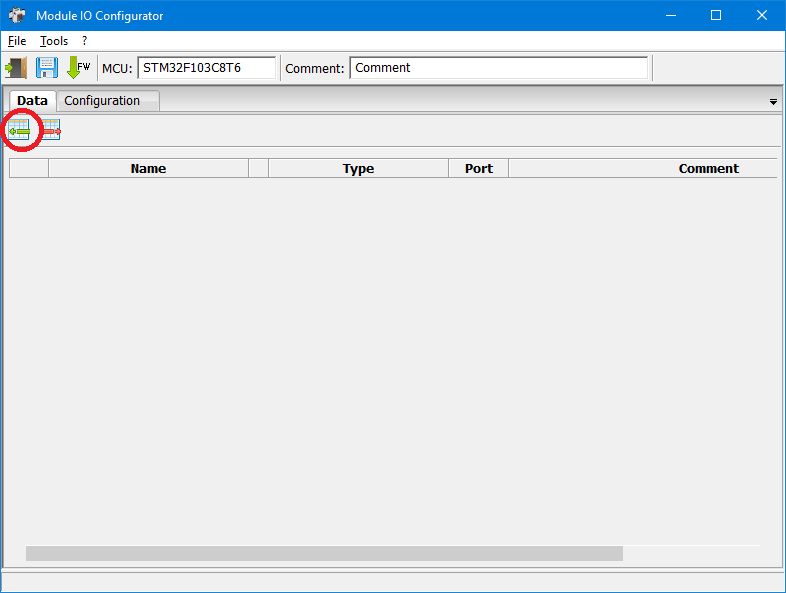
Add row to variable table
Generate BSP code (F8 button)
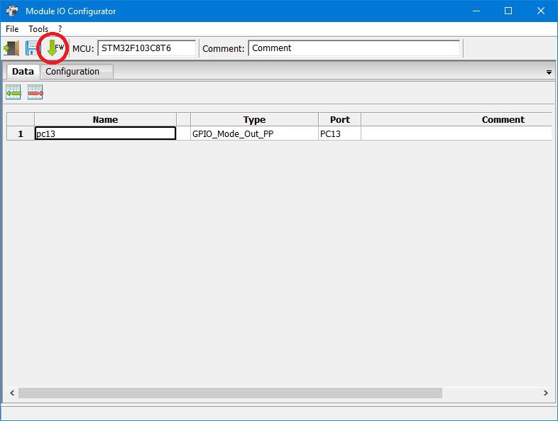
Further, every time after a project change, BSP generation is mandatory!
Open the created project in the development environment of EmBitz or Keil. EmBitz is still a workaround. It seems that the author abandoned this project. Apparently in the future, the project will use Code :: Blocks.
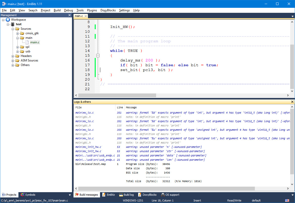
In the main.c file, write the following:

(To increase the size of the image, open it in a new tab)
In EmBitz, press F2, after the information window appears, press F7. The compilation should be done.
Pressing F2 again will hide the information bookmarks.
Download to the microcontroller, see how it works.
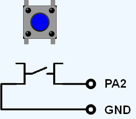
Button
Add a button, for example this:

Wiring diagram:
Add a variable to the table:
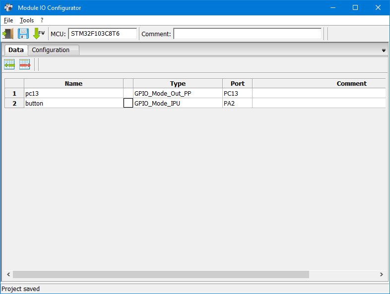
We generate BSP.
Change the program to the following:
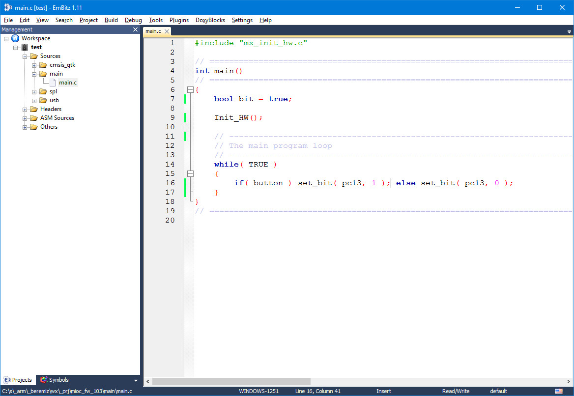
We create a new BSP (F8), compile it, load it into the microcontroller.
We press the button - the LED lights up, release - it goes out.
Instead of an LED, a relay can be connected to another port, for example:

And manage some kind of payload.
Output messages to the console
You need to determine what will be the console.
The options are:
- USB-UART adapter
- virtual COM port (Micro-USB cable)
If both UART1 and USB as Console are selected in the configuration, and USB VCP is not selected, then the console will be assigned to nowhere. Those. there will be no swearing at the print_str function (or the print macro), but there will be no output either. The same behavior will be if you do not select any interface, or select USB VCP but do not select either UART1 or USB as Console.
Console Configuration:

Connect TettaTerm to the COM port (console). If we download the firmware via UART1, then do not forget to disconnect / connect the COM port. In TerraTerm "hot buttons" Alt + I; Alt + N This is not required for the boot option via ST-Link.
Edit the program:
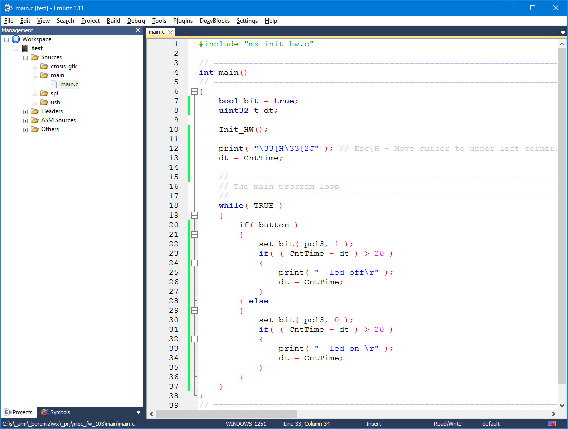
Now the status of the button will be displayed on the console:

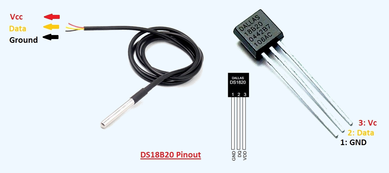
DS18B20
Connect the DS18B20 temperature sensor to the “tablet”.
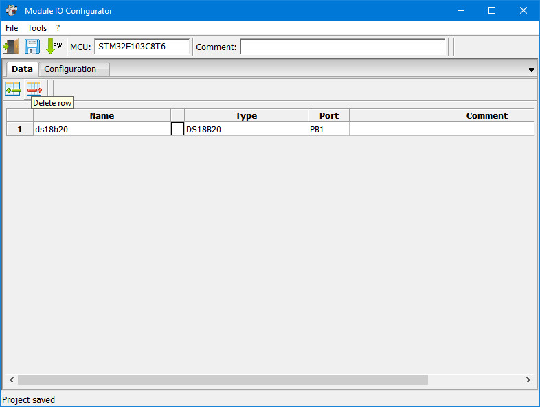
Put the variable in the table:
Change the program to the following:
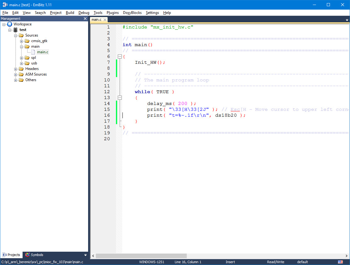
We create a new configuration, compile, load it into the microcontroller.
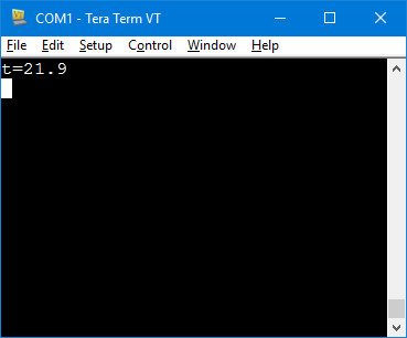
The console will display the temperature measured by the sensor.
ADC
As an example of working with the ADC, you can use the potentiometer:

Or soil moisture sensor
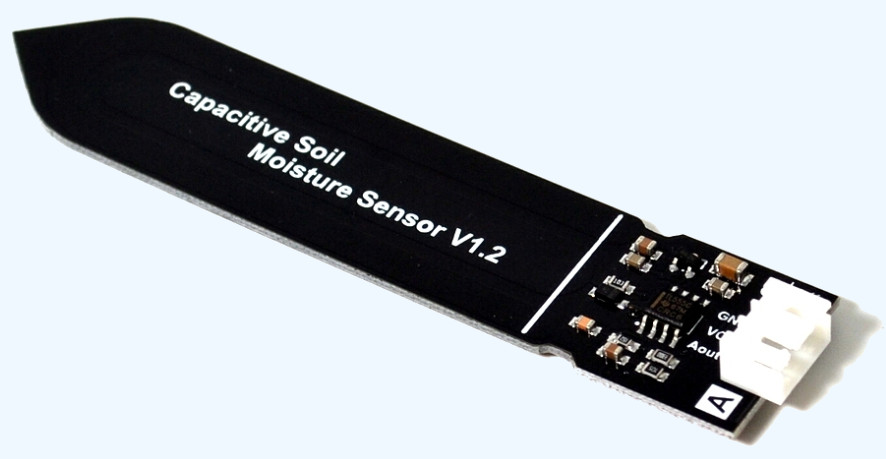
Let us dwell on the last one:
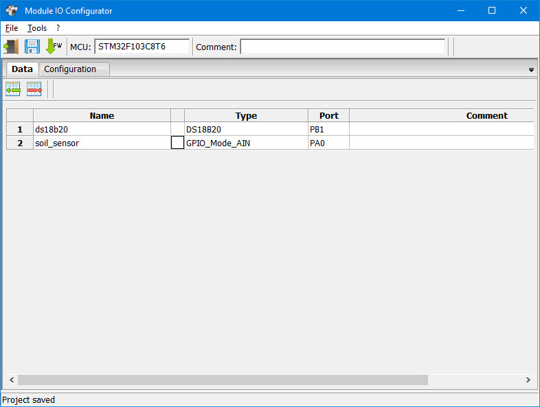
Configure the port:
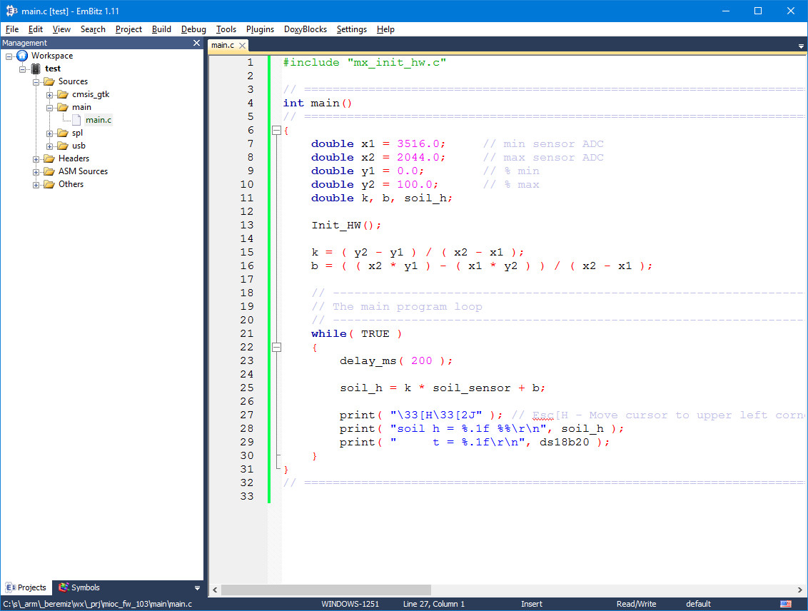
Editing the program:
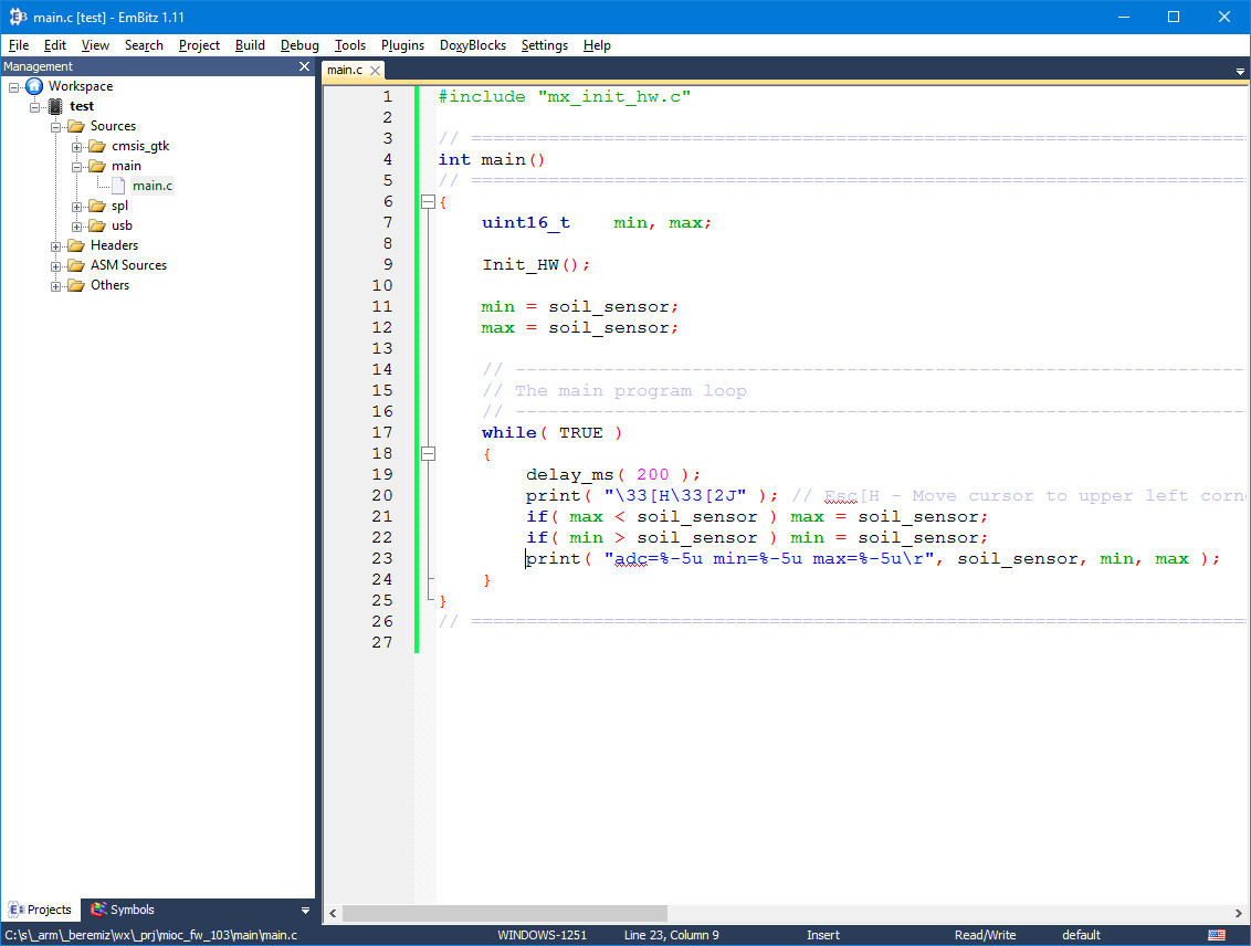
We compile, load.
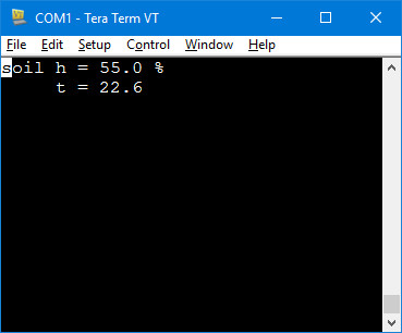
In the console we observe:
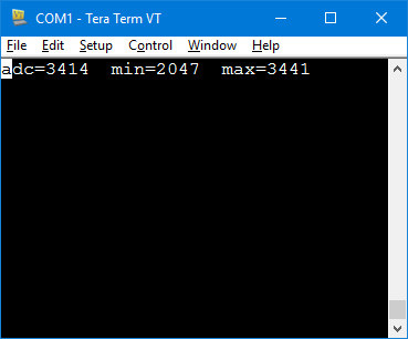
adc - current ADC reading. max and min - recorded minimum and maximum sensor readings, completely dry (0%) and very wet (100%).
Very wet (100%) - put the sensor in a glass of water. Very dry (0%) - lies in the open air.
In fact, we calibrated the soil moisture sensor from 0 to 100%. We place the maximum and minimum values in the program text.
The result of the work. The sensor is placed in the ground of the flower pot:
This project is a solution template for watering plants.
That's all for now. The MIOC program will be replenished with additional features.
All Articles