Design Electromechanical Marble Machine v2.0
I want to talk about the second version of my electro-mechanical Marble Machine and the process of its design. About the first spiral car I already wrote here on a hub Since then, not a little time has passed, and now, in principle, the plan has been implemented: two lifts and two descents work together as one system, transfer balls to each other, mixing them randomly. Honestly, I don’t like everything here, something needs to be reworked or more finely tuned, but I’m glad that in general I did it. The result on the video!
I am a programmer. When programming, it often happens that you write and debug the code for a week, but then, rethinking it, you simply delete everything that was created by overwork in a week, and you write again in two hours already clean, working and combed. When developing my Marble Machine, I came across the fact that here, in the physical world, this principle does not work. It either works, but weakly ... or I don’t understand yet how to make it work in this way.
There are a number of problems.
The first problem is probably my insufficiently high qualification as a designer of marble machines; I think this is a temporary drawback, maybe I can still pump my skills. I used the KOMPAS-3D design environment. To tell you the truth, mastering this tool is not easy. Perhaps now I can use approximately 2-3% of the COMPASS capabilities. I had to re-read a bunch of instructions and revise a bunch of demo videos on youtube. Currently, I have learned to design individual parts, but I still do not know how to draw them into a single design in a 3D model to make sure that the rotating parts interact correctly, do not cling to each other where it is not necessary, that their movement is sufficient. Then, I don’t really imagine if in modern 3D editors it is possible to simulate the movement of free parts, for example, the movement of a ball along an inclined plane, modeling the place where the ball falls and so on. In general, there is something for me to learn.
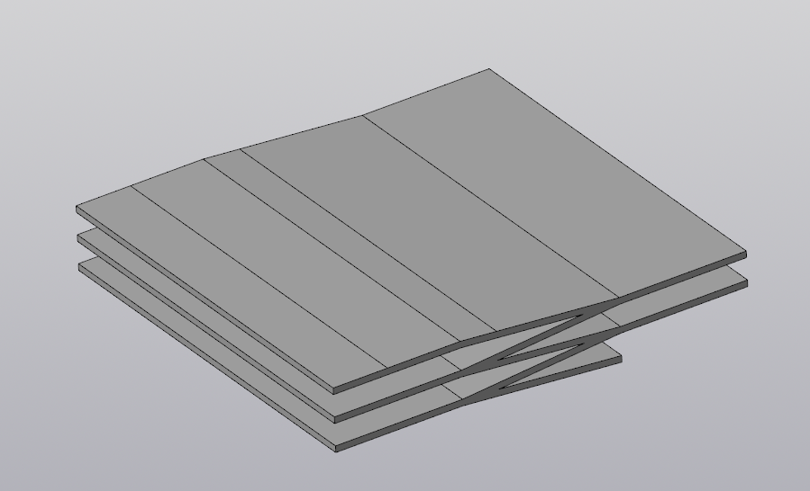
I can give such an example of my self-training in COMPASS. Even when I was designing the first spiral Marble Machines, I ran into the problem that I did not know how to make several planes located at a small angle. It is easy to design parts in which the main planes are orthogonal. But what if I need a descending snake? I then came up with and used this strange trick (nothing better then crossed my mind):

I drew a descent profile on the plane, then squeezed it out:
Then he cut off all that was superfluous by projecting sketches from above:
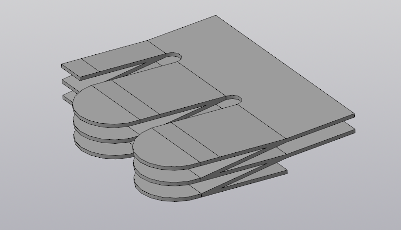
Now I already understand how difficult and stupid it was to use such a technique. It would be much easier to use the offset compass planes, but then I could not do it ... Now I would have made such a detail much easier.
The second problem is partly related to the first problem - it is printing time. A 3D printer with layered printing takes quite a while. It turns out that if I do not yet know how to model the interaction of parts in software, then to check the operability of the node you need to spend a lot of time and plastic. It happened to me that I design two parts, then print, but they do not fit together well and something needs to be changed in the model. And this again is a waste of time and plastic. But plastic is not expensive at all, it’s not so pathetic, but the time ... yes, it’s pity.
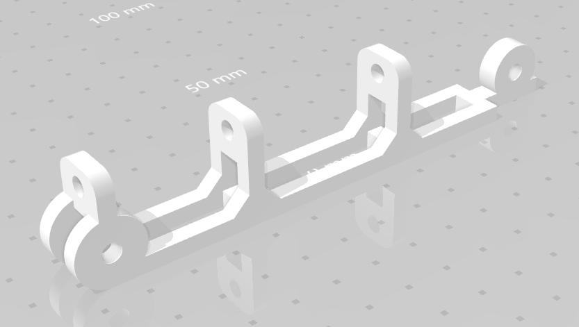
The third problem is the lack of experience. Many of the mistakes I made come from naivety and inexperience. Marble Machine is a robot machine with countless states, if you count the locations of all the balls as a separate state. The machine has many moving mechanical parts. When designing the crane, I hoped that I would be able to connect the moving plastic parts through the holes in them simply with screws / studs and nuts on the washers. But it turned out that this does not work. The holes designed in the plastic parts after printing are either too small, too large, or quickly become loose during operation. The nuts, even through the washers, are always loosened. Self-locking nuts with a nylon ring improve the situation, but the play is still unacceptable. Do not tighten the nut - it will hang, and tighten - there will be a lot of friction, the motor will not pull. I tested all this on myself until I understood what should be done as correctly as possible, namely: everywhere bearings should be placed on moving parts. Such a simple solution, which removes the backlash and excellent mobility, minimal friction and nothing spontaneously unscrews. I had to redo many models to use the bearing. For example, here are models of two connecting rod parts for a stepper motor:
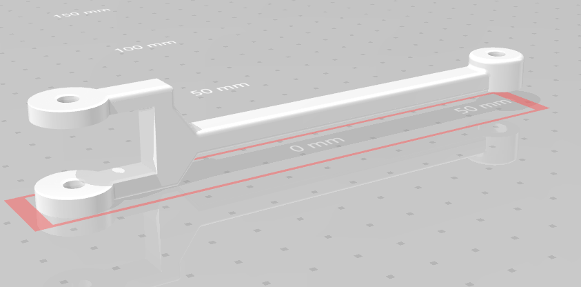
and so:
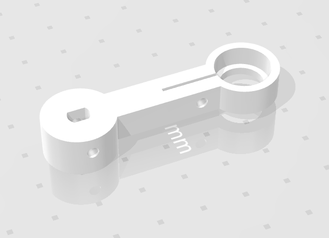
Now they are connected through a bearing. I designed a groove from the bearing seat so that it was possible to insert the bearing tightly into the interference fit and there is even the possibility to tighten it with a screw.
These photos show the places where the bearings are now standing:
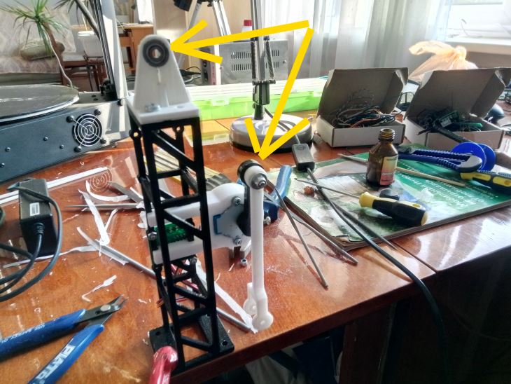
and further:

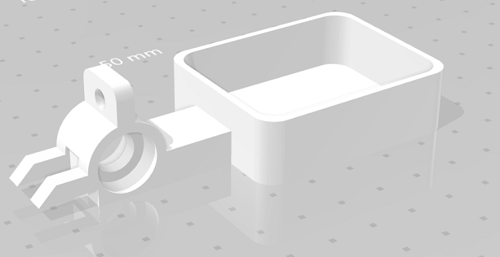
Then, the next problem is the rigidity of the structure. As you can see, I am trying to create a kind of mechanical robotic art object, and the combination of white, black and shiny metal is not accidental. In the crane rod, I wanted to put a metal stud M4. She had to give the bar the necessary strength and would have to shine "in the rays of spotlights" (if I had them). However, it did not work out. With a metal stud, the weight and inertia of the bar increases significantly. My poor stepper motor hardly pulled such a bar up, but she almost fell down. Here I had to take extreme measures: I printed on my printer a plastic white pin (white PLA) with a diameter of 4 millimeters, which I simply glued inside the bar to where I wanted to put the metal pin. It turned out well. Not very tough, but very lightweight construction. The second idea that came to me later - the crane should be with a counterweight! And why didn’t I immediately think about it? Here is the question: redo the model and retype the entire bar or print a small addition to the existing bar and “work with a file”? I chose the second, so faster - I made a separate part that would contain a place for bearings and a box under the load - a counterweight:
I sawed off the tail from the rod and glued a new part to the old one using dichloroethane.

Here the photo shows the place of gluing. Although ... not everything is clear here, because how to balance the tap? He has a variable weight when he drops balls ... I must say that I still underestimated the weight of the metal balls themselves. Although they are not large, 12.5 mm, each weighs 8 grams, but they act on a wide shoulder. When the crane lifts three balls at once, and then throws them in the upper position, elastic vibrations occur on the rod. And how would I take them into account in advance? I can’t imagine. Is it possible to somehow calculate in COMPASS or other CAD?
In general, when developing this Marble Machine, I was faced with the fact that a lot of things do not work as I imagine. For example, the simplest is a funnel for collecting balls. Here I did a 3D rendering of this part:

It would seem that what could go wrong here? But in fact, even this funnel works differently, not the way I thought! I made the bottom as a part of the surface of the sphere and thought that the balls would roll along such a bowl and their speed would increase as they moved down to the outlet. But no! It turns out that the balls are rolling and lower downhill the steepness of the surface is less, they slow down as they approach the exit. Perhaps the steps of 0.2 mm play the role of the thickness of the print layer? Something is not quite what I wanted or thought. But at least he did not remodel this place.
Another important issue is how to dock two marbles of a machine into one? I already had a spiral machine and it works, can it be left as is? To agree on the level of the flow of balls from the first spiral machine, I had to completely disassemble it, design it in COMPASS and print the stand for the spiral rack to make it higher and reassemble the machine. Then it was necessary to come up with a flow switch, a trigger, a trap under a trigger, tracks and turns. In general, the creation process was quite interesting. I have a friend, and his wife is an artist, and I remember drawing a picture with fish for a long time. I come to visit them, I look, such normal fish. After a week I come - and the fish in the same picture are already swimming in the other direction. So I had something like that too. Today I came up with and did it, but tomorrow I rethought and redesigned everything, printed another model, installed it, tested it.
Next, I’ll tell you what other details were designed. Below is a 3D render of these models. Crane Stand:

On a rack landing openings under engine driver cards are provided.
I attach the second part to the crane stand: stepper motor holder:
An unexpected problem also arose - the holder turned out to be too strong and too thick. Now the engine has problems with cooling. You may have to redesign this site.
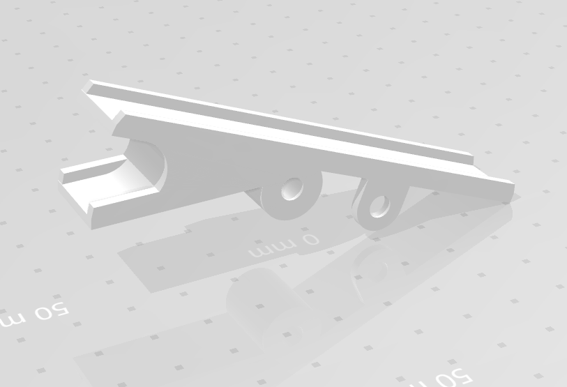
On the rack from above, the “triangle” part is fastened with screws with a bearing seat, to support the crane rod:

Two parts from the crane bar:
and so:

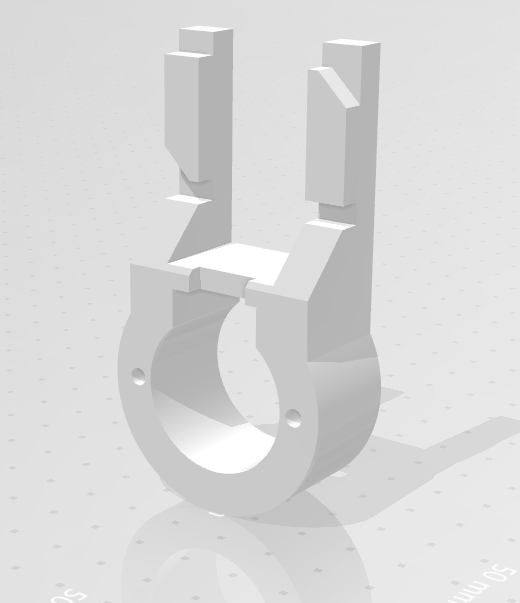
One of the most important parts is the trigger trigger:
and another bowl for catching balls from a trigger:

There are many other minor details that one way or another had to be invented, designed and printed on the go.
To tell you the truth, after assembling all the mechanics, when I switched to the electrical and to the software part of the project, I even breathed a sigh of relief, right there everything is simple!

To program the FPGA board of the Mars rover 3bis, start two stepper motors, connect the crane solenoid and organize a survey of the reed switch, it seemed to me a much simpler task than the design and implementation of the mechanics of the Marble Machine robot. But FPGA programming, that's another story, if anyone is interested, you can read here .
Now I'm already thinking about designing the following types of lifts for the next version of Marble Machine v3. There are options here: Archimedes screw, step hoists, gears. There is something to think about and something to puzzle over.
All Articles