Come up with Powercheck technology
I was always interested in how the charge indicator on Duracell batteries works and works:
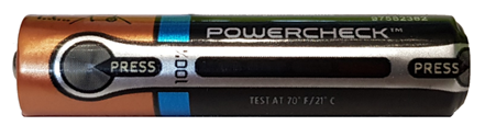
And also why under it it is indicated that it is necessary to test at 21 ° C. But before you look at the solution that is used in batteries, let's try to come to it on our own.
As you know, one way to check the battery charge is to measure the voltage at its terminals, and the higher it is, the better the battery is charged. The simplest and most common way to measure voltage is the indirect method, in which the current flowing through a resistor with a known rating is measured.
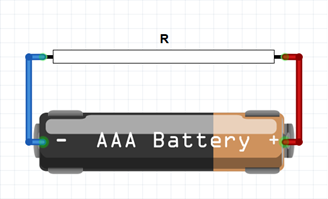
In this case, the current flowing through the resistor R will be:
- create a constant electromagnetic field;
- heat the resistor.
The first effect is not very interesting to us, because we need to get the device as simple as possible, albeit with some measurement error. But then it is widely used in analog electromechanical voltmeters.
The second effect is more interesting since with its help, in combination with thermo-paint, you can get the simple indicator we need. Consider this solution. A stripe of bright color is applied to the insulating film of the battery from the outside, which will serve as an indicator, and is covered with thermo-paint, which will become transparent as it warms up. On the inside of the insulating film, a layer of conductive material with a certain resistance is applied. And the indicator seems to be ready?
Let's look at the limitations of this solution and try to solve them. Firstly, the resistor on the reverse side of the insulation will heat evenly, and accordingly, the degree of charge can only be determined by how brightly the indicator strip is visible through the thermal paint. We can assume that when the strip is not visible, the battery is completely discharged, and when the charge is fully visible, the charge is 100%. In this case, it is necessary to apply color samples for several charge levels, with which it will be necessary to compare the current indicator reading. This can cause difficulties in reading intermediate values.
Is it possible to make the indicator strip appear not all at once, but starting from any end? Then it will become easier to determine the charge level, because the charge level may, for example, correspond to the percentage of the indicator that appears.
From the Joule-Lenz law for direct current and resistance, the amount of heat released in the conductor depends on the values of current, resistance and time. Because there is only one resistance in the circuit, then one current flows through it. The indicator on time is user-defined. Of the quantities that can be changed, only resistance remains. What if the resistance of the resistor is made uneven? For example, like this:

The width of the resistor in the figure determines the width of the resistor on the insulation. The wider the section of the resistor, the larger its cross-section, and therefore the less resistance it has. The diagram can be redrawn as follows:
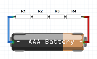
Where one non-uniform resistor is represented by four series-connected resistors, such that R1> R2> R3> R4. In addition, increasing the width of the resistor increases the area with which heat is dissipated i.e. areas with less resistance will heat up more slowly and cool faster.
Thus, using non-uniform resistance, it is possible to obtain an indicator in which the indicator strip will appear from a given side (from the side having greater resistance) and to a given level (determined by a steady thermal balance). An example is the previous version of the indicator:
Secondly, the battery case is made of metal i.e. It has a specific heat capacity and conducts heat well. It turns out that the case will serve as a good radiator for our indicator. Therefore, it is necessary to put thermal insulation between the indicator and the housing, as heating the entire battery case to the required temperature is not the best option. As a heat-insulating pad, you can use paper, cardboard or air. For example, make a substrate only around the perimeter of the indicator.
Thirdly, in order to save power, the indicator cannot be constantly on. So you need a button to turn it on. We have a metal battery case and a conductive resistor layer insulated by a gasket from the case. The design is very similar to a membrane button, it remains only to make a hole in the insulation and the button will be ready:
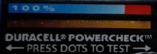
In total, the indicator we came up with consists of an indicator strip, on the outside of the battery insulation, coated with thermo paint. A resistor with uneven resistance is applied on the inside and is separated from the battery case by a thermal pad, with the help of which a membrane button is made to turn on the indicator. So we came to the solution that is used in Duracell batteries, and now you can watch how it is implemented in them:
Now the requirement for using this indicator at 21 ° C is clear. And finally, the battery indicator type AAA, depending on the flowing current:
All Articles