Training Cisco 200-125 CCNA v3.0. Day 22. Third CCNA: continue to study RIP
I have already said that I will be updating my video tutorials to CCNA v3. Everything that you learned in previous lessons is fully consistent with the new course. If the need arises, I will include additional topics in new lessons, so you don’t have to worry about matching our lessons with 200-125 CCNA.
First, we will fully explore the topics of the first exam 100-105 ICND1. We have a few more lessons left, after which you will be ready to pass this exam. Then we will begin to study the course of ICND2. I guarantee that by the end of this video course you will be fully prepared to pass the 200-125 exam. In the last lesson, I said that we will no longer return to the RIP protocol because it is not part of the CCNA course. But since RIP was included in the third version of CCNA, we will continue to study it.
The topics of today's lesson will be three problems that arise in the process of using RIP: Counting to Infinity, or counting to infinity, Split Horizon - split horizon rules and Route Poison, or route poisoning.

To understand the essence of the problem of counting ad infinitum, let us turn to the scheme. Suppose we have router R1, router R2, and router R3. The first router is connected to the second network 192.168.2.0/24, the second to the third network 192.168.3.0/24, the network 192.168.1.0/24 is connected to the first router, and the network 192.168.4.0/24 is connected to the third router.
Let's look at the route to the network 192.168.1.0/24 from the first router. In his table, this route will be displayed as 192.168.1.0 with the number of hopes equal to 0.
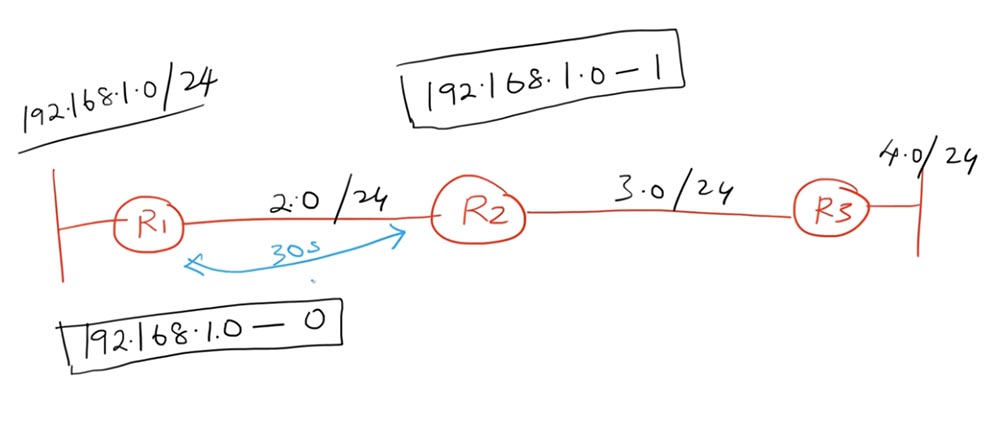
For the second router, the same route will be displayed in the table as 192.168.1.0 with the number of hopes equal to 1. At the same time, the routing table of the routers is updated with the Update timer every 30 seconds. R1 tells R2 that the network 192.168.1.0 is accessible through it with the number of hopes equal to 0. Upon receiving this message, R2 will respond with an update that the same network is accessible through it in one hop. This is how ordinary RIP routing works.
Imagine a situation where the connection between R1 and the network 192.168.1.0/24 turned out to be disconnected, after which the router lost access to it. At the same time, router R2 sends an update to router R1, in which it reports that the network 192.168.1.0/24 is available to it in one hop. R1 knows that it has lost access to this network, but R2 assures that this network is accessible through it in one hop, so the first router believes that it is obliged to update its routing table by changing the number of hopes from 0 to 2.
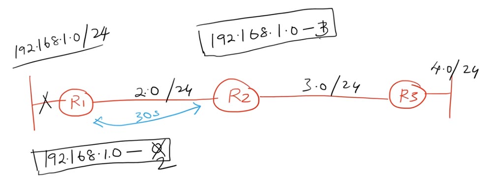
After that, R1 sends an update to router R2. He says: “ok, before that you sent me an update that the network 192.168.1.0 is available with zero hop counts, now you are reporting that the route to this network can be built in 2 hop. So I have to update my routing table from 1 to 3. " The next update, R1 will change the number of hopes to 4, the second router to 5, then to 5 and 6, and this process will continue indefinitely.
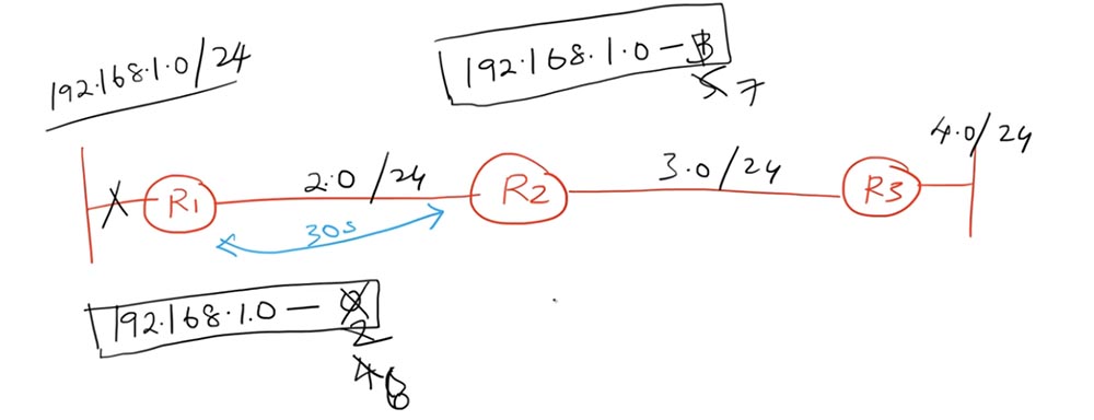
This problem is known as the “routing loop”, and in the RIP protocol it is called the “counting to infinity problem”. In fact, the network 192.168.1.0/24 is not available, but R1, R2 and all other routers in the network believe that it can be accessed because the route is constantly looped. This problem can be solved with the help of mechanisms for splitting horizons and poisoning the route. Consider the network topology with which we will work today.
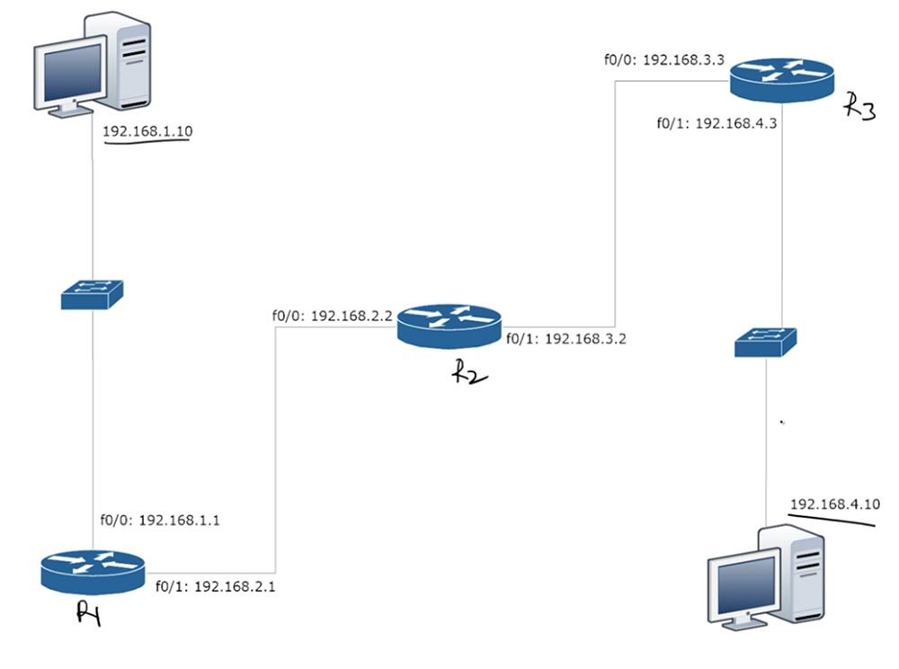
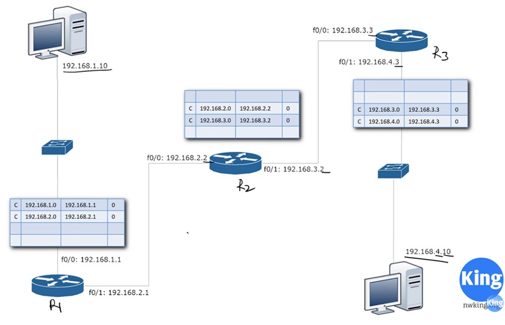
There are three R1,2,3 routers and two computers with IP addresses 192.168.1.10 and 192.168.4.10 on the network. Between computers there are 4 networks: 1.0, 2.0, 3.0 and 4.0. Routers have IP addresses, where the last octet means the number of the router, and the last but one means the network number. You can assign any addresses to these network devices, but I prefer these, because it is easier for me to explain.
To set up our network, let's move on to Packet Tracer. I use the Cisco 2911 model routers and use this scheme to assign IP addresses to both hosts - PC0 and PC1.
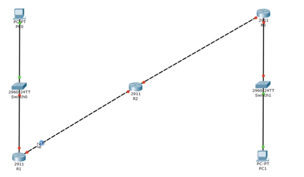
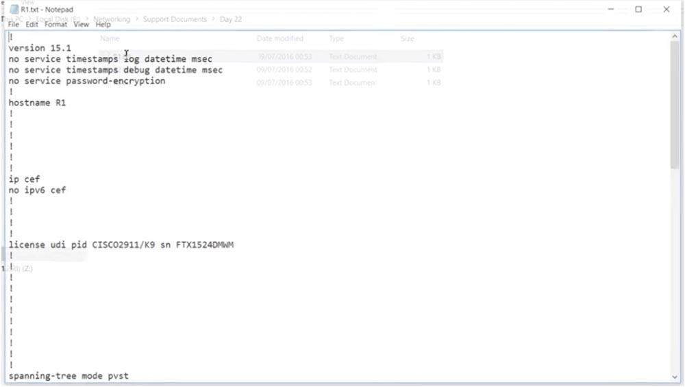
You can ignore the switches, because they are “out of the box” and by default use VLAN1. 2911 routers have two gigabit ports. In order to make it easier for us, I use ready-made configuration files for each of these routers. You can visit our website, go to the Resources tab and view all our video tutorials.

Currently, there are not all updates, but as an example, you can take a look at the Day 13 lesson, which contains the Workbook link, or Workbook. The same link will be attached to today's video tutorial, and by clicking on it, you can download the router configuration files.
In order to configure our routers, I just copy the contents of the R1 configuration text file, open its console in Packet Tracer and enter the config t command.
Then I just paste the copied text and exit the settings.
In the same way I deal with the settings of the second and third routers. This is one of the advantages of Cisco settings - you can simply copy and paste the necessary parameters into the configuration files of network devices. In my case, I will also add 2 commands to the beginning of the finished configuration files so that they do not enter them into the console - these are en (enable) and config t. Then copy the contents and paste it in its entirety into the R3 settings console.
So, we configured all 3 routers. If you want to use ready-made configuration files for your routers, make sure that the models match the ones shown in this diagram - here the routers have GigabitEthernet ports. You may need to fix this line in a file on FastEthernet if your router has these ports.
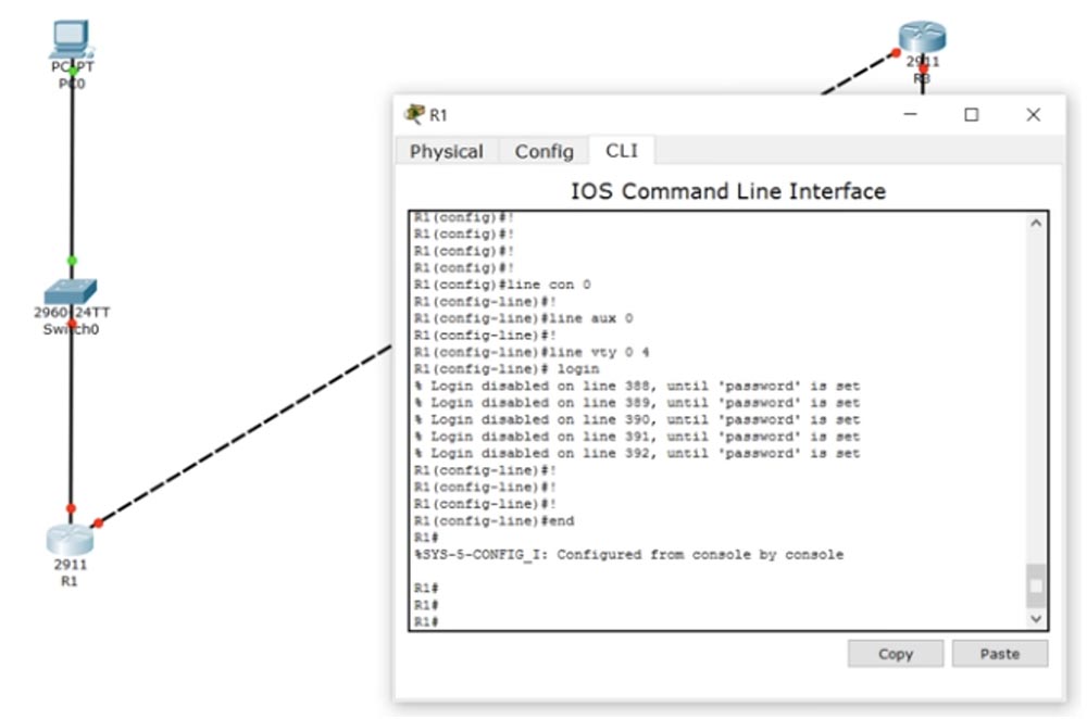
You can see that the port markers of the routers in the diagram are still red. What is the problem? For diagnostics, we’ll go into the IOS command line interface of router 1 and type the command show ip interface brief. This team is your “Swiss knife” in solving various network problems.
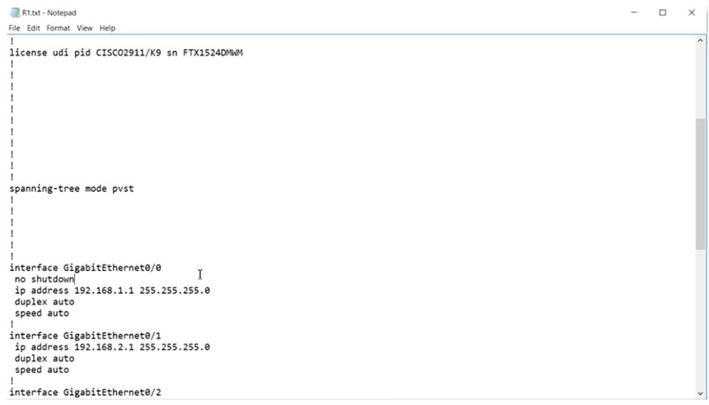
Yes, we have a problem - you see that the GigabitEthernet 0/0 interface is in an administratively down state. The fact is that in the copied configuration file I forgot to use the no shutdown command and now I will enter it manually.
Now I have to manually add this line to the settings of all routers, after which the port markers will turn green. Now I will display on the common screen all three windows of the CLI routers, so that it is more convenient to watch my actions.
Currently, RIP is configured on all 3 devices, and I will debug it, for which I use the debug ip rip command, after which all devices will exchange RIP updates. After that, I use the undebug all command for all 3 routers.
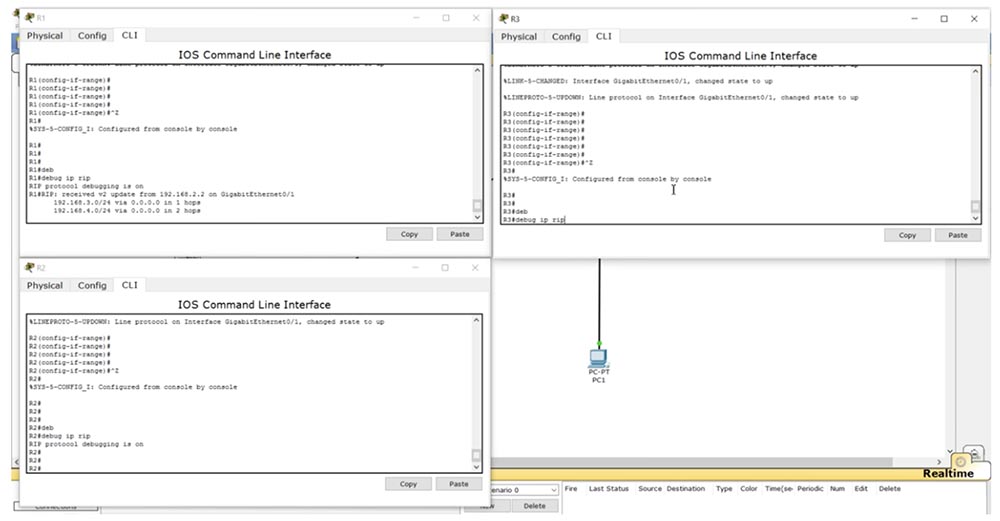
You see that R3 had a problem finding a DNS server. In the future, we will discuss CCNA v3 topics related to DNS servers, and I will show you how to disable the search function of this server. For now, let's get back to the topic of the lesson and see how the RIP update works.
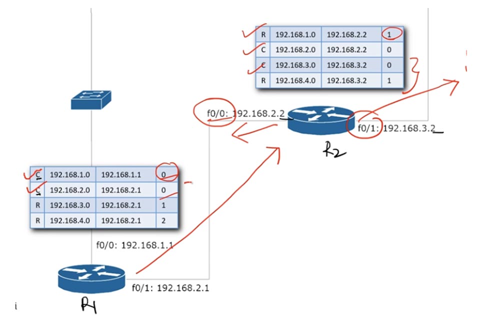
After we enable routers, records about networks that are directly connected to their ports will appear in their routing tables. In the tables, these entries are headed by the letter C, and the number of hops in a direct connection is 0.
When R1 sends an update to router R2, it contains information about the networks 192.168.1.0 and 192.168.2.0. Since R2 already knows about the 192.168.2.0 network, it only places an update on the 192.168.1.0 network in its routing table.
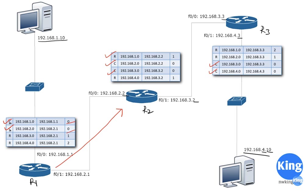
This entry is entitled R, which means that connection to the network 192.168.1.0 is possible through the router interface f0 / 0: 192.168.2.2 only via the RIP protocol with 1 hop count.
Similarly, when R2 sends an R3 update, the third router places a record in its routing table that the network 192.168.1.0 is accessible through the interface of the router 192.168.3.3 via RIP with the number of hopes 2. This is how the routing update works.
To prevent routing loops, or counting to infinity, the RIP protocol has a “horizon splitting” mechanism. This mechanism is a rule: "do not send an update about the network or route through the interface through which you received this update." In our case, it looks like this: if R2 received an update from R1 about the network 192.168.1.0 through the f0 / 0: 192.168.2.2 interface, it should not send an update about this network 2.0 to the first router via the f0 / 0 interface. It can send only updates that relate to the networks 192.168.3.0 and 192.168.4.0 through this interface associated with the first router. He also should not send an update about the network 192.168.2.0 through the f0 / 0 interface, because this interface already knows about it, because this network is connected directly to it. So, when the second router sends the update to the first router, it should contain records only about networks 3.0 and 4.0, so he learned about these networks from another interface - f0 / 1.
This is the simple rule for splitting the horizon: never send information about any route back in the same direction from which this information came. This rule prevents a routing loop or count to infinity.
If you turn to Packet Tracer, you can see that R1 received an update from 192.168.2.2 through the GigabitEthernet0 / 1 interface about only two networks: 3.0 and 4.0. The second router did not say anything about networks 1.0 and 2.0, because it learned about these networks through this very interface.
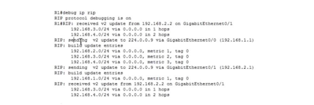
The first R1 router sends an update to the multicast IP address 224.0.0.9 - it does not send a broadcast message. This address is something like the specific frequency at which FM radio stations are broadcast, that is, only those devices that are configured for this multicast address will receive a message. In the same way, routers configure themselves to receive traffic for address 224.0.0.9. So, R1 sends an update to this address through the GigabitEthernet0 / 0 interface with the IP address 192.168.1.1. This interface should transmit updates only about networks 2.0, 3.0 and 4.0, because network 1.0 is connected directly to it. We see that he does just that.
Then he sends an update through the second interface f0 / 1 with the address 192.168.2.1. Do not pay attention to the letter F, meaning FastEthernet - this is just an example, since our routers have GigabitEthernet interfaces, which should be indicated by the letter g. He cannot send an update about networks 2.0, 3.0 and 4.0 through this interface, because he learned about them through the f0 / 1 interface, therefore he sends the update only about network 1.0.
Let's see what happens if the connection to the first network is lost for some reason. In this case, R1 immediately activates a mechanism called route poisoning. It consists in the fact that as soon as the connection to the network disappears, the number of hopes in the record about this network in the routing table immediately increases to 16. As we know, the number of hopes equal to 16 means that this network is not available.
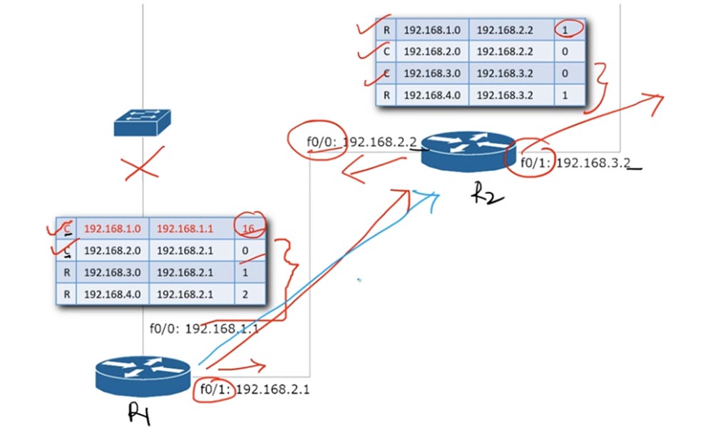
In this case, the Update timer is not used, this is a trigger update, which is instantly routed over the network to the nearest router. I will mark it in the diagram in blue. The R2 router receives an update that says that from now on the network 192.168.1.0 is available with a hop count of 16, that is, it is unavailable. This is called route poisoning. As soon as R2 receives this update, it immediately changes the value of the hop in the recording line 192.168.1.0 to 16 and sends this update to the third router. In turn, R3 also changes the number of hopes for an unavailable network to 16. Thus, all devices connected via RIP will recognize that the 192.168.1.0 network is no longer available.
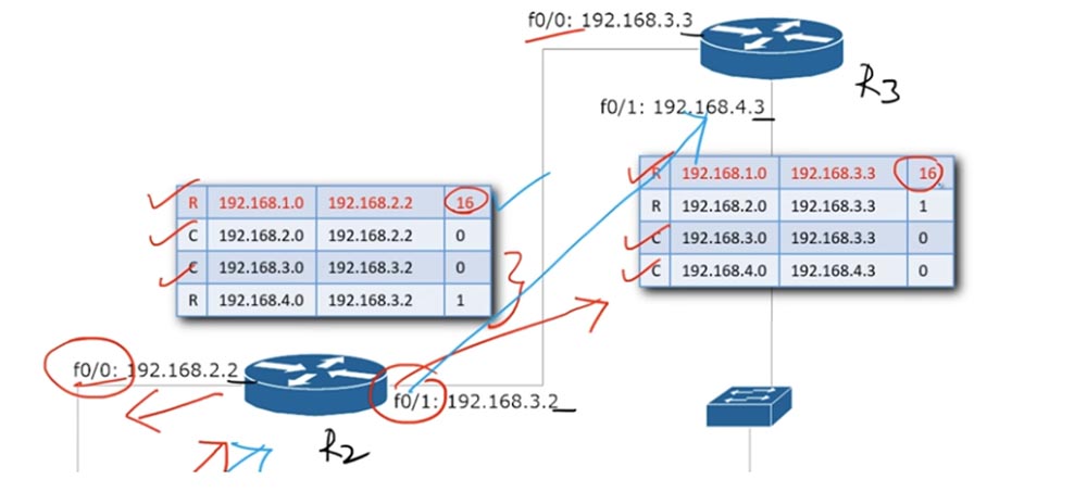
This process is called convergence. This means that all routers update their routing tables to the current status, excluding the route to the network 192.168.1.0 from them.
So, we have covered all the topics of today's lesson. Now I will show you the commands that are used to diagnose and troubleshoot network problems. In addition to the show ip interface brief command, there is a show ip protocols command. It shows the parameters and status of the routing protocol for devices that use dynamic routing.
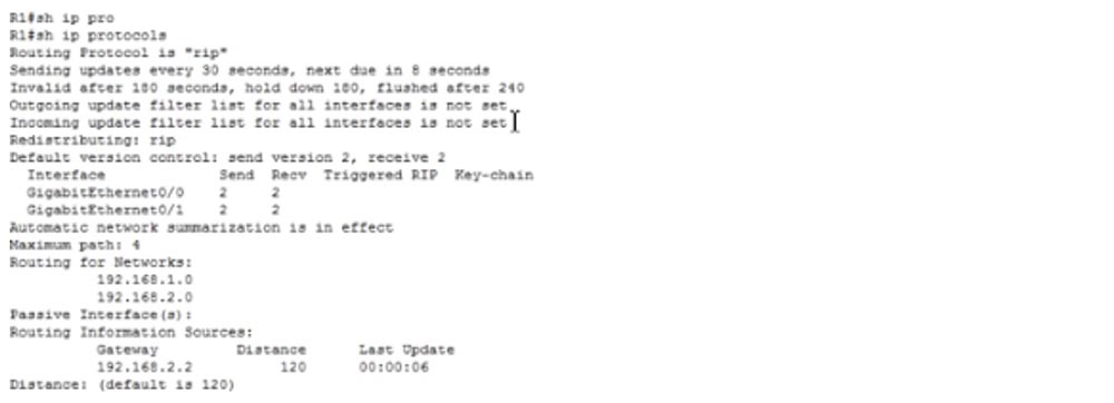
After using this command, information about the protocols that are used by this router appears. It says here that the routing protocol is RIP, updates are sent every 30 seconds, the next update will be sent out after 8 seconds, the Invalid timer starts after 180 seconds, the Hold Down timer after 180 seconds, the Flush timer after 240 seconds. These values can be changed, however, the topics of our CCNA course do not address these issues, so we will use the default timer values. Similarly, our course does not address issues of outgoing and incoming filter list updates for all router interfaces.
Redistribution of protocols - RIP - is indicated below, this parameter is applied when the device uses several protocols, for example, it shows how RIP interacts with OSPF and how OSPF interacts with RIP. Redistribution is also not part of your CCNA course.
It is further shown that the protocol uses auto-summarization of routes, which we talked about in the previous video and that the administrative distance is 120, which we also discussed.
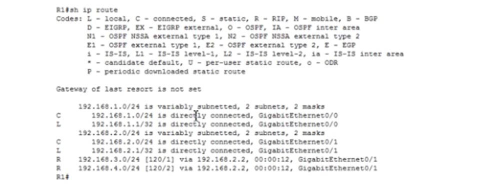
Let's take a closer look at the show ip rout command. You see that the networks 192.168.1.0/24 and 192.168.2.0/24 are directly connected to the router, two more networks, 3.0 and 4.0, use the RIP routing protocol. Both of these networks are accessible through the GigabitEthernet0 / 1 interface and a device with an IP address of 192.168.2.2. The information in square brackets is important - the first number indicates the administrative distance, or administrative distance, the second is the number of hopes. Hop count is a RIP metric. Other protocols, such as OSPF, have their own metrics, which we will discuss when exploring the relevant topic.
As we have already discussed, administrative distance means a degree of trust. The maximum degree of trust has a static route with an administrative distance of 1. Therefore, the lower this value, the better.
Suppose that the network 192.168.3.0/24 is accessible both through the g0 / 1 interface using RIP and through the g0 / 0 interface that uses static routing. In this case, the router will direct all traffic along the static route through f0 / 0, because this route deserves more trust. In this sense, RIP with an administrative distance of 120 is worse than a static routing protocol with a distance of 1.
Another important command for troubleshooting is the show ip interface g0 / 1 command. It displays all the information about the parameters and status of a particular router port.
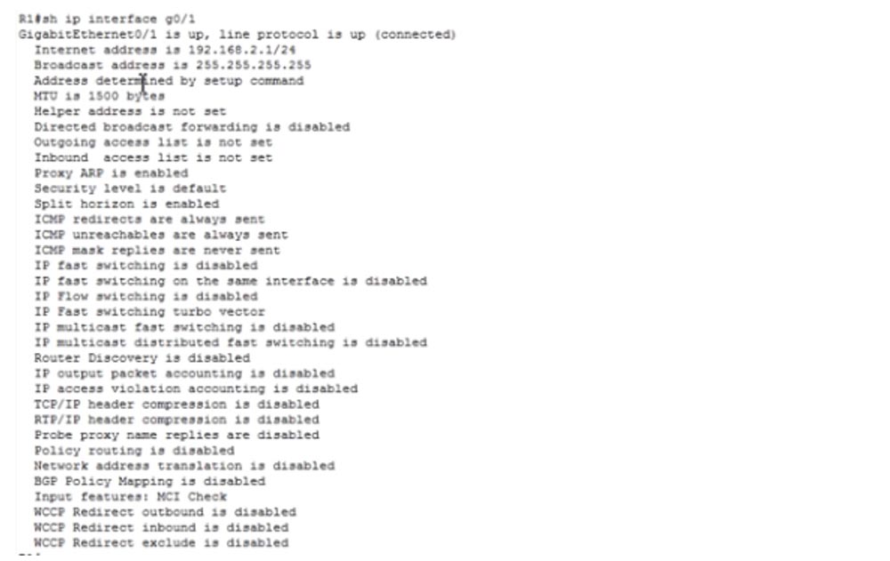
The line that says that split horizon is enabled is important for us: Split horizon is enabled, because you may have problems because this mode is disabled. Therefore, if a problem occurs, you must make sure that the split horizon mode is activated for this interface. I note that by default this mode is active.
I believe that we have covered enough questions related to the RIP protocol, so you should not have any difficulties with this topic when passing the exam.
Thank you for staying with us. Do you like our articles? Want to see more interesting materials? Support us by placing an order or recommending it to your friends, a 30% discount for Habr users on a unique analogue of entry-level servers that we invented for you: The whole truth about VPS (KVM) E5-2650 v4 (6 Cores) 10GB DDR4 240GB SSD 1Gbps from $ 20 or how to divide the server? (options are available with RAID1 and RAID10, up to 24 cores and up to 40GB DDR4).
Dell R730xd 2 times cheaper? Only we have 2 x Intel TetraDeca-Core Xeon 2x E5-2697v3 2.6GHz 14C 64GB DDR4 4x960GB SSD 1Gbps 100 TV from $ 199 in the Netherlands! Dell R420 - 2x E5-2430 2.2Ghz 6C 128GB DDR3 2x960GB SSD 1Gbps 100TB - from $ 99! Read about How to Build Infrastructure Bldg. class c using Dell R730xd E5-2650 v4 servers costing 9,000 euros for a penny?
First, we will fully explore the topics of the first exam 100-105 ICND1. We have a few more lessons left, after which you will be ready to pass this exam. Then we will begin to study the course of ICND2. I guarantee that by the end of this video course you will be fully prepared to pass the 200-125 exam. In the last lesson, I said that we will no longer return to the RIP protocol because it is not part of the CCNA course. But since RIP was included in the third version of CCNA, we will continue to study it.
The topics of today's lesson will be three problems that arise in the process of using RIP: Counting to Infinity, or counting to infinity, Split Horizon - split horizon rules and Route Poison, or route poisoning.
To understand the essence of the problem of counting ad infinitum, let us turn to the scheme. Suppose we have router R1, router R2, and router R3. The first router is connected to the second network 192.168.2.0/24, the second to the third network 192.168.3.0/24, the network 192.168.1.0/24 is connected to the first router, and the network 192.168.4.0/24 is connected to the third router.
Let's look at the route to the network 192.168.1.0/24 from the first router. In his table, this route will be displayed as 192.168.1.0 with the number of hopes equal to 0.
For the second router, the same route will be displayed in the table as 192.168.1.0 with the number of hopes equal to 1. At the same time, the routing table of the routers is updated with the Update timer every 30 seconds. R1 tells R2 that the network 192.168.1.0 is accessible through it with the number of hopes equal to 0. Upon receiving this message, R2 will respond with an update that the same network is accessible through it in one hop. This is how ordinary RIP routing works.
Imagine a situation where the connection between R1 and the network 192.168.1.0/24 turned out to be disconnected, after which the router lost access to it. At the same time, router R2 sends an update to router R1, in which it reports that the network 192.168.1.0/24 is available to it in one hop. R1 knows that it has lost access to this network, but R2 assures that this network is accessible through it in one hop, so the first router believes that it is obliged to update its routing table by changing the number of hopes from 0 to 2.
After that, R1 sends an update to router R2. He says: “ok, before that you sent me an update that the network 192.168.1.0 is available with zero hop counts, now you are reporting that the route to this network can be built in 2 hop. So I have to update my routing table from 1 to 3. " The next update, R1 will change the number of hopes to 4, the second router to 5, then to 5 and 6, and this process will continue indefinitely.
This problem is known as the “routing loop”, and in the RIP protocol it is called the “counting to infinity problem”. In fact, the network 192.168.1.0/24 is not available, but R1, R2 and all other routers in the network believe that it can be accessed because the route is constantly looped. This problem can be solved with the help of mechanisms for splitting horizons and poisoning the route. Consider the network topology with which we will work today.
There are three R1,2,3 routers and two computers with IP addresses 192.168.1.10 and 192.168.4.10 on the network. Between computers there are 4 networks: 1.0, 2.0, 3.0 and 4.0. Routers have IP addresses, where the last octet means the number of the router, and the last but one means the network number. You can assign any addresses to these network devices, but I prefer these, because it is easier for me to explain.
To set up our network, let's move on to Packet Tracer. I use the Cisco 2911 model routers and use this scheme to assign IP addresses to both hosts - PC0 and PC1.
You can ignore the switches, because they are “out of the box” and by default use VLAN1. 2911 routers have two gigabit ports. In order to make it easier for us, I use ready-made configuration files for each of these routers. You can visit our website, go to the Resources tab and view all our video tutorials.
Currently, there are not all updates, but as an example, you can take a look at the Day 13 lesson, which contains the Workbook link, or Workbook. The same link will be attached to today's video tutorial, and by clicking on it, you can download the router configuration files.
In order to configure our routers, I just copy the contents of the R1 configuration text file, open its console in Packet Tracer and enter the config t command.
Then I just paste the copied text and exit the settings.
In the same way I deal with the settings of the second and third routers. This is one of the advantages of Cisco settings - you can simply copy and paste the necessary parameters into the configuration files of network devices. In my case, I will also add 2 commands to the beginning of the finished configuration files so that they do not enter them into the console - these are en (enable) and config t. Then copy the contents and paste it in its entirety into the R3 settings console.
So, we configured all 3 routers. If you want to use ready-made configuration files for your routers, make sure that the models match the ones shown in this diagram - here the routers have GigabitEthernet ports. You may need to fix this line in a file on FastEthernet if your router has these ports.
You can see that the port markers of the routers in the diagram are still red. What is the problem? For diagnostics, we’ll go into the IOS command line interface of router 1 and type the command show ip interface brief. This team is your “Swiss knife” in solving various network problems.
Yes, we have a problem - you see that the GigabitEthernet 0/0 interface is in an administratively down state. The fact is that in the copied configuration file I forgot to use the no shutdown command and now I will enter it manually.
Now I have to manually add this line to the settings of all routers, after which the port markers will turn green. Now I will display on the common screen all three windows of the CLI routers, so that it is more convenient to watch my actions.
Currently, RIP is configured on all 3 devices, and I will debug it, for which I use the debug ip rip command, after which all devices will exchange RIP updates. After that, I use the undebug all command for all 3 routers.
You see that R3 had a problem finding a DNS server. In the future, we will discuss CCNA v3 topics related to DNS servers, and I will show you how to disable the search function of this server. For now, let's get back to the topic of the lesson and see how the RIP update works.
After we enable routers, records about networks that are directly connected to their ports will appear in their routing tables. In the tables, these entries are headed by the letter C, and the number of hops in a direct connection is 0.
When R1 sends an update to router R2, it contains information about the networks 192.168.1.0 and 192.168.2.0. Since R2 already knows about the 192.168.2.0 network, it only places an update on the 192.168.1.0 network in its routing table.
This entry is entitled R, which means that connection to the network 192.168.1.0 is possible through the router interface f0 / 0: 192.168.2.2 only via the RIP protocol with 1 hop count.
Similarly, when R2 sends an R3 update, the third router places a record in its routing table that the network 192.168.1.0 is accessible through the interface of the router 192.168.3.3 via RIP with the number of hopes 2. This is how the routing update works.
To prevent routing loops, or counting to infinity, the RIP protocol has a “horizon splitting” mechanism. This mechanism is a rule: "do not send an update about the network or route through the interface through which you received this update." In our case, it looks like this: if R2 received an update from R1 about the network 192.168.1.0 through the f0 / 0: 192.168.2.2 interface, it should not send an update about this network 2.0 to the first router via the f0 / 0 interface. It can send only updates that relate to the networks 192.168.3.0 and 192.168.4.0 through this interface associated with the first router. He also should not send an update about the network 192.168.2.0 through the f0 / 0 interface, because this interface already knows about it, because this network is connected directly to it. So, when the second router sends the update to the first router, it should contain records only about networks 3.0 and 4.0, so he learned about these networks from another interface - f0 / 1.
This is the simple rule for splitting the horizon: never send information about any route back in the same direction from which this information came. This rule prevents a routing loop or count to infinity.
If you turn to Packet Tracer, you can see that R1 received an update from 192.168.2.2 through the GigabitEthernet0 / 1 interface about only two networks: 3.0 and 4.0. The second router did not say anything about networks 1.0 and 2.0, because it learned about these networks through this very interface.
The first R1 router sends an update to the multicast IP address 224.0.0.9 - it does not send a broadcast message. This address is something like the specific frequency at which FM radio stations are broadcast, that is, only those devices that are configured for this multicast address will receive a message. In the same way, routers configure themselves to receive traffic for address 224.0.0.9. So, R1 sends an update to this address through the GigabitEthernet0 / 0 interface with the IP address 192.168.1.1. This interface should transmit updates only about networks 2.0, 3.0 and 4.0, because network 1.0 is connected directly to it. We see that he does just that.
Then he sends an update through the second interface f0 / 1 with the address 192.168.2.1. Do not pay attention to the letter F, meaning FastEthernet - this is just an example, since our routers have GigabitEthernet interfaces, which should be indicated by the letter g. He cannot send an update about networks 2.0, 3.0 and 4.0 through this interface, because he learned about them through the f0 / 1 interface, therefore he sends the update only about network 1.0.
Let's see what happens if the connection to the first network is lost for some reason. In this case, R1 immediately activates a mechanism called route poisoning. It consists in the fact that as soon as the connection to the network disappears, the number of hopes in the record about this network in the routing table immediately increases to 16. As we know, the number of hopes equal to 16 means that this network is not available.
In this case, the Update timer is not used, this is a trigger update, which is instantly routed over the network to the nearest router. I will mark it in the diagram in blue. The R2 router receives an update that says that from now on the network 192.168.1.0 is available with a hop count of 16, that is, it is unavailable. This is called route poisoning. As soon as R2 receives this update, it immediately changes the value of the hop in the recording line 192.168.1.0 to 16 and sends this update to the third router. In turn, R3 also changes the number of hopes for an unavailable network to 16. Thus, all devices connected via RIP will recognize that the 192.168.1.0 network is no longer available.
This process is called convergence. This means that all routers update their routing tables to the current status, excluding the route to the network 192.168.1.0 from them.
So, we have covered all the topics of today's lesson. Now I will show you the commands that are used to diagnose and troubleshoot network problems. In addition to the show ip interface brief command, there is a show ip protocols command. It shows the parameters and status of the routing protocol for devices that use dynamic routing.
After using this command, information about the protocols that are used by this router appears. It says here that the routing protocol is RIP, updates are sent every 30 seconds, the next update will be sent out after 8 seconds, the Invalid timer starts after 180 seconds, the Hold Down timer after 180 seconds, the Flush timer after 240 seconds. These values can be changed, however, the topics of our CCNA course do not address these issues, so we will use the default timer values. Similarly, our course does not address issues of outgoing and incoming filter list updates for all router interfaces.
Redistribution of protocols - RIP - is indicated below, this parameter is applied when the device uses several protocols, for example, it shows how RIP interacts with OSPF and how OSPF interacts with RIP. Redistribution is also not part of your CCNA course.
It is further shown that the protocol uses auto-summarization of routes, which we talked about in the previous video and that the administrative distance is 120, which we also discussed.
Let's take a closer look at the show ip rout command. You see that the networks 192.168.1.0/24 and 192.168.2.0/24 are directly connected to the router, two more networks, 3.0 and 4.0, use the RIP routing protocol. Both of these networks are accessible through the GigabitEthernet0 / 1 interface and a device with an IP address of 192.168.2.2. The information in square brackets is important - the first number indicates the administrative distance, or administrative distance, the second is the number of hopes. Hop count is a RIP metric. Other protocols, such as OSPF, have their own metrics, which we will discuss when exploring the relevant topic.
As we have already discussed, administrative distance means a degree of trust. The maximum degree of trust has a static route with an administrative distance of 1. Therefore, the lower this value, the better.
Suppose that the network 192.168.3.0/24 is accessible both through the g0 / 1 interface using RIP and through the g0 / 0 interface that uses static routing. In this case, the router will direct all traffic along the static route through f0 / 0, because this route deserves more trust. In this sense, RIP with an administrative distance of 120 is worse than a static routing protocol with a distance of 1.
Another important command for troubleshooting is the show ip interface g0 / 1 command. It displays all the information about the parameters and status of a particular router port.
The line that says that split horizon is enabled is important for us: Split horizon is enabled, because you may have problems because this mode is disabled. Therefore, if a problem occurs, you must make sure that the split horizon mode is activated for this interface. I note that by default this mode is active.
I believe that we have covered enough questions related to the RIP protocol, so you should not have any difficulties with this topic when passing the exam.
Thank you for staying with us. Do you like our articles? Want to see more interesting materials? Support us by placing an order or recommending it to your friends, a 30% discount for Habr users on a unique analogue of entry-level servers that we invented for you: The whole truth about VPS (KVM) E5-2650 v4 (6 Cores) 10GB DDR4 240GB SSD 1Gbps from $ 20 or how to divide the server? (options are available with RAID1 and RAID10, up to 24 cores and up to 40GB DDR4).
Dell R730xd 2 times cheaper? Only we have 2 x Intel TetraDeca-Core Xeon 2x E5-2697v3 2.6GHz 14C 64GB DDR4 4x960GB SSD 1Gbps 100 TV from $ 199 in the Netherlands! Dell R420 - 2x E5-2430 2.2Ghz 6C 128GB DDR3 2x960GB SSD 1Gbps 100TB - from $ 99! Read about How to Build Infrastructure Bldg. class c using Dell R730xd E5-2650 v4 servers costing 9,000 euros for a penny?
All Articles