Training Cisco 200-125 CCNA v3.0. Day 21. RIP Remote Vector Routing
The topic of today's lesson is RIP, or Routing Information Protocol. We will talk about various aspects of its application, its configuration and limitations. As I already said, the topic of RIP is not included in the curriculum of the Cisco 200-125 CCNA course, but I decided to devote a separate lesson to this protocol, since RIP is one of the main routing protocols.
Today we will consider 3 aspects: understanding of the work and setting up RIP in routers, RIP timers, RIP restrictions. This protocol was created in 1969, so it is one of the oldest network protocols. Its advantage lies in its extraordinary simplicity. Today, many network devices, including Cisco, continue to support RIP, because it is not proprietary like EIGRP, but a public protocol.
There are 2 versions of RIP. The first, classic version does not support VLSM - the variable length of the subnet mask on which classless IP addressing is based, so we can use only one network. I will talk about this a little later. This version also does not support authentication.
Suppose you have 2 routers connected to each other. In this case, the first router tells the neighbor everything that he knows. Suppose network 10 is connected to the first router, network 20 is located between the first and second router, and network 30 is located behind the second router. Then the first router tells the second that it knows networks 10 and 20, and router 2 tells router 1 that it knows about network 30 and network 20.

The routing protocol indicates that these two networks need to be added to the routing table. In general, it turns out that one router talks about the networks connected to it to a neighboring router, one to its neighbor, etc. Simply put, RIP is a gossip protocol that serves to ensure that neighboring routers share information with each other, and each of the neighbors unconditionally believes what they told him. Each router “listens” for changes in the network and shares them with its neighbors.
The lack of authentication support means that any router that will be connected to the network immediately becomes its full member. If I want to bring down the network, I will connect my hacker router with malicious updates to it, and since all other routers trust it, they will update their routing tables as I need. Against such a hack, the first version of RIP does not provide any protection.
RIPv2 can provide authentication by configuring the router accordingly. In this case, updating information between routers will become possible only after passing through network authentication by entering a password.
RIPv1 uses Broadcasting, that is, all updates are sent using broadcast messages, so that they are received by all network participants. Suppose a computer is connected to the first router that does not know anything about these updates, since only routing devices need them. However, router 1 will send these messages to all devices that have a Broadcast ID, that is, even to those who do not need it.
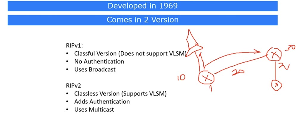
In the second version of RIP, this problem is solved - it uses Multicast ID, or multicast traffic. In this case, only those devices that are specified in the protocol settings receive updates. In addition to authentication, this version of RIP supports classless VLSM IP addressing. This means that if a 10.1.1.1/24 network is connected to the first router, then all network devices whose IP address is in the address range of this subnet also receive updates. The second version of the protocol supports the CIDR method, that is, when the second router receives the update, it knows which particular network or route it is concerned. In the case of the first version, if a 10.1.1.0 network is connected to the router, then devices of the 10.0.0.0 network and other networks belonging to the same class will also receive updates. At the same time, router 2 will also receive complete information about updating these networks, however, without CIDR, it will not know that this information concerns a subnet with class A IP addresses.
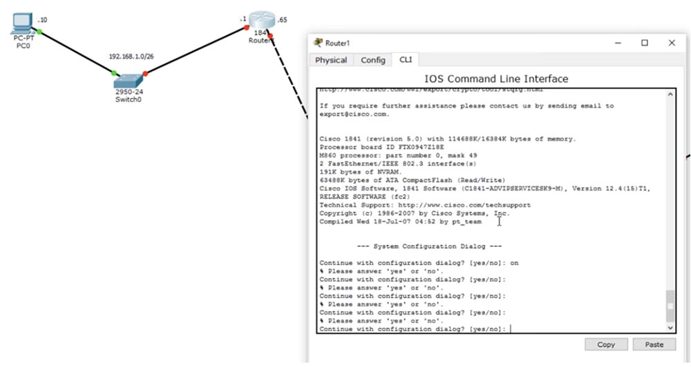
This is what RIP is in very general terms. Now let's look at how it can be configured. You need to go into global configuration mode of the router settings and use the Router RIP command.

After that, you will see that the command line header has changed to R1 (config-router) #, because we have moved to the sub-command level of the router. The second command will be Version 2, that is, we tell the router that it should use version 2 of the protocol. Next, we must enter the address of the announced class network through which updates should be transmitted using the network XXXX command. This command has 2 functions: first, it indicates which network should be announced, and second, which interface should be used for this. You will understand what I mean when you look at the network configuration.

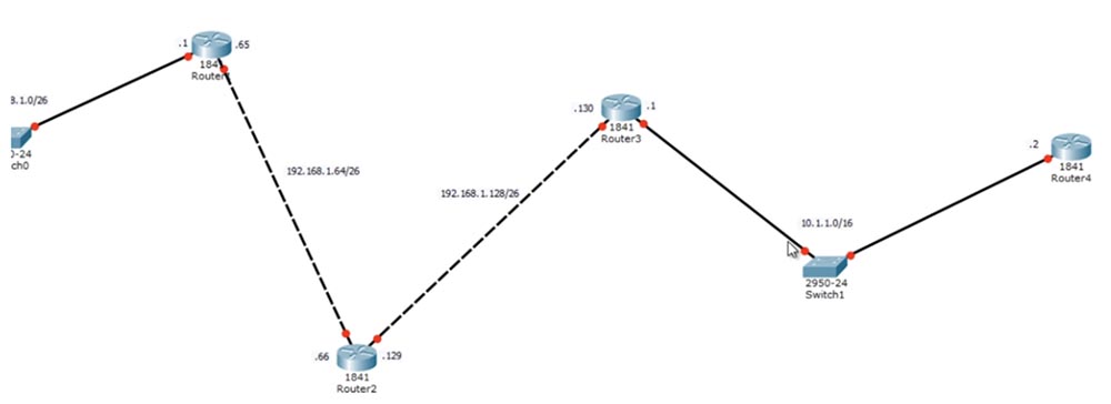
Here we have 4 routers and a computer connected to the switch through a network with the identifier 192.168.1.0/26, which is divided into 4 subnets. We use only 3 subnets: 192.168.1.0/26, 192.168.1.64/26 and 192.168.1.128/26. We still have the 192.168.1.192/26 subnet, but it is not used due to uselessness.
The device ports have the following IP addresses: computer 192.168.1.10, first port of the first router 192.168.1.1, second port 192.168.1.65, first port of the second router 192.168.1.66, second port of the second router 192.168.1.129, first port of the third router 192.168.1.130 . Last time we talked about agreements, so I can’t follow the convention and assign the address .1 to the second port of the router, because .1 is not part of this network.
Further, I use other addresses, because we start another network - 10.1.1.0/16, so the second port of the second router to which this network is connected has the IP address 10.1.1.1, and the port of the fourth router to which the switch is connected - address 10.1.1.2.
In order to configure the network I created, I must assign IP addresses to the devices. Let's start with the first port of the first router.
First, create the host name R1, assign the address 192.168.1.1 to the port f0 / 0 and specify the subnet mask 255.255.255.192, since we have a network of the form / 26. We complete the configuration of R1 with the no shut command. The second port of the first f0 / 1 router will receive the IP address 192.168.1.65 and the subnet mask 255.255.255.192.
The second router will receive the name R2, the first port f0 / 0 we will assign the address 192.168.1.66 and the subnet mask 255.255.255.192, the second port f0 / 1 - the address 192.168.1.129 and the subnet mask 255.255.255.192.
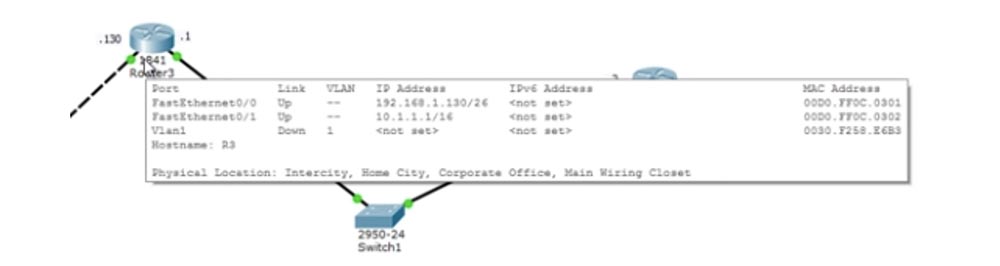
Moving to the third router, we will assign it the host name R3, port f0 / 0 will receive the address 192.168.1.130 and mask 255.255.255.192, and port f0 / 1 will receive the address 10.1.1.1 and mask 255.255.0.0, because this network is / 16.
Finally, I will go to the last router, give it the name R4 and assign the address 10.1.1.2 and the mask 255.255.0.0 to the port f0 / 0. So, we configured all network devices.
Finally, let's look at the network settings of the computer - it has a static IP address of 192.168.1.10, a half-net mask of 255.255.255.192, and the default gateway address is 192.168.1.1.

So, you saw how the subnet mask is configured for devices in different subnets, it is very simple. Now enable routing. I go into the settings of R1, set the global configuration mode and type the router command. After that, the system gives hints of possible routing protocols for this command: bgp, eigrp, ospf, and rip. Since our tutorial is about RIP, I use the router rip command.
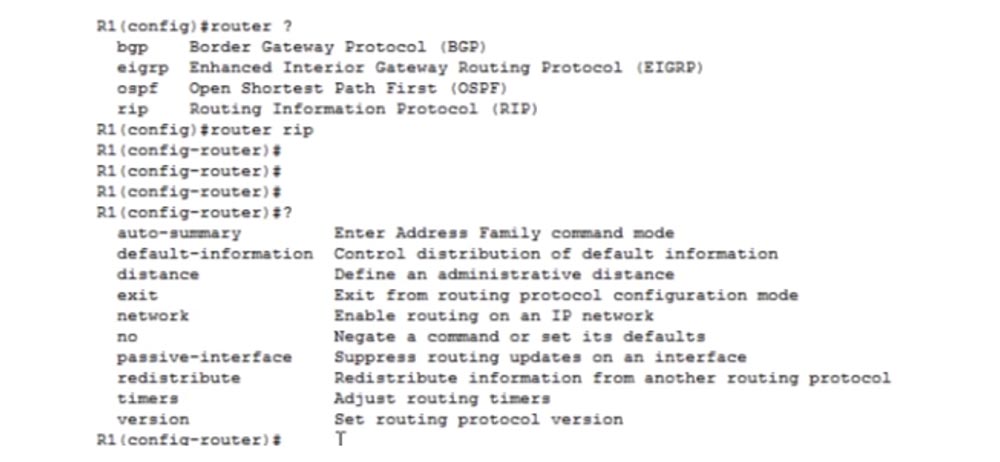
If you type a question mark, the system will give a new hint for the following command with possible options for the functions of this protocol: auto-summary - automatic route summarization, default-information - control of the default information presentation, network - networks, timings, and so on. Here you can select the information that we will exchange with neighboring devices. The most important function is the version, so we will start by entering the version 2 command. Next, we need to use the key network command, which creates the route for the specified IP network.
We will continue to configure Router1 later, and now I want to go to router 3. Before I use the network command for it, let's look at the right side of our network topology. The second port of the router has the address 10.1.1.1. How does RIP work? Even in the second version of RIP, as a rather old protocol, it still uses its own network classes. Therefore, despite the fact that our network 10.1.1.0/16 belongs to class A, we must specify the full version of the class of this IP address using the network 10.0.0.0 command.
But even if I type the network 10.1.1.1 command and then look at the current configuration, I will see that the system fixed 10.1.1.1 to 10.0.0.0, automatically using the full-class addressing format. So if you have a question about RIP in the CCNA exam, you will need to use full-class addressing. If instead of 10.0.0.0 you type 10.1.1.1 or 10.1.0.0, then make an error. Despite the fact that conversion to a full-class addressing form occurs automatically, I advise you to use the correct address initially so that you don’t have to wait until the system corrects the error. Remember - RIP always uses full-class network addressing.
After you use the network 10.0.0.0 command, the third router will insert this tenth network into the routing protocol and send the update along the R3-R4 route. Now you need to configure the routing protocol of the fourth router. I go into its settings and enter the router rip, version 2 and network 10.0.0.0 commands sequentially. With this command, I ask R4 to start announcing network 10. using the RIP routing protocol.

Now these two routers could exchange information, but that would not change anything. Using the show ip route command shows that FastEthernrt 0/0 is directly connected to the 10.1.0.0 network. The fourth router, having received the announcement of the network from the third router, will say: "Fine, buddy, I received your announcement of the tenth network, but I already know about it because I am directly connected to this network."
Therefore, we will return to the settings of R3 and insert another network with the network 192.168.1.0 command. I am using the full-class addressing format again. After that, the third router will be able to announce the network 192.168.1.128 along the route R3-R4. As I already said, RIP is a “gossip” that talks about new networks to all its neighbors, passing them information from its routing table. If you now look at the table of the third router, you can see the data of two networks connected to it.
He will transmit this data to both ends of the route to both the second and fourth routers. Let's move on to the R2 settings. I enter the same router rip, version 2, and network 192.168.1.0 commands, and here the fun begins. I am specifying a network of 1.0, but this is both the network 192.168.1.64/26 and the network 192.168.1.128/26. Therefore, when I specify the network 192.168.1.0, I technically provide routing for both interfaces of this router. Convenience is that with just one command you can specify routing for all ports of the device.
I specify the exact same parameters for the R1 router and in the same way I provide routing for both interfaces. If you now look at the routing table R1, you can see all the networks.

This router knows about network 1.0 and network 1.64. He also knows about networks 1.128 and 10.1.1.0, because he uses RIP. This is indicated by the heading R in the corresponding row of the routing table.
I ask you to pay attention to the information [120/2] - this is the administrative distance, that is, the reliability of the source of routing information. This value may have a larger or smaller value, but by default it is 120 for the RIP protocol. For example, a static route has an administrative distance of 1. The smaller the administrative distance, the more reliable the protocol. If the router will be able to choose between two protocols, for example between a static route and RIP, then it will choose to forward traffic along the static route. The second value in parentheses, / 2, is the metric. In the RIP protocol, the metric means the number of hopes. In this case, the network 10.0.0.0/8 can be reached in 2 hop, that is, the R1 router should send traffic over the network 192.168.1.64/26, this is the first hop, and over the network 192.168.1.128/26, this is the second hop to get to the network 10.0.0.0/8 through a device with FastEthernet 0/1 interface with an IP address of 192.168.1.66.
For comparison, the R1 router can reach the network 192.168.1.128 with an administrative distance of 120 per 1 hop through the interface 192.168.1.66.
Now, if you try to ping the interface of the R4 router with the IP address 10.1.1.2 from PC0, it will successfully return.
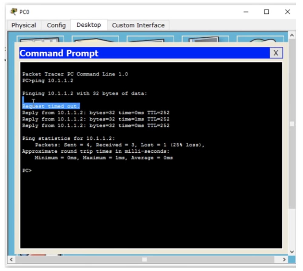
The first attempt failed with the Request timed out message, because when using ARP, the first packet disappears, but the other three successfully returned to the destination. In this way, peer-to-peer communication occurs on a network using the RIP routing protocol.
So, in order to activate the use of the RIP protocol by the router, you need to type the router rip, version 2 and network <network number / network identifier in full-class form> commands in sequence.
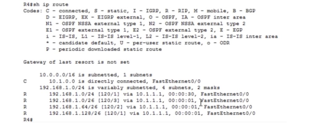
We go into the settings of R4 and enter the command show ip route. You see that network 10. is connected directly to the router, and network 192.168.1.0/24 is accessible through port f0 / 0 with IP address 10.1.1.1 via RIP protocol.
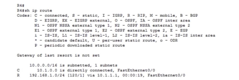
If you pay attention to the type of network 192.168.1.0/24, you will notice that there is a problem of auto-summing of routes. If auto-summarization is enabled, the RIP protocol will summarize all networks up to 192.168.1.0/24. Let's look at what timers are. RIP has 4 basic timers.
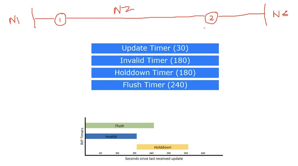
The Update timer is responsible for the frequency of sending updates, every 30 seconds sending protocol updates on all interfaces involved in RIP routing. This means that he takes the routing table and sends it to all ports operating in RIP mode.
Imagine that we have router 1, which is connected to router 2 by network N2. Before the first and after the second router there are networks N1 and N3. Router 1 tells router 2 that it knows the network N1 and N2, and sends it an update. Router 2 tells router 1 that it knows the networks N2 and N3. At the same time, every 30 seconds, the ports of the routers exchange routing tables.
Imagine, for some reason, the N1-R1 connection has broken and Router 1 can no longer connect to the N1 network. After that, the first router will only send updates to the second router regarding the N2 network. Router 2, having received the first such update, will think: “excellent, now I have to put the N1 network in the Invalid Timer network timer”, and then start the Invalid timer. For 180 seconds, he will not exchange updates with the N1 network with anyone, but after this period of time, he stops Invalid Timer and starts Update Timer again. If during these 180 seconds he does not receive any status updates for the N1 network, he will place it in the Hold Down timer for 180 seconds, that is, the Hold Down timer starts immediately after the Invalid timer ends.
At the same time, another, fourth Flush timer is running, which starts simultaneously with the Invalid timer. This timer determines the time interval between the receipt of the last normal update about the N1 network until this network is excluded from the routing table. Thus, when the duration of this timer reaches 240 seconds, network N1 is automatically excluded from the routing table of the second router.
So, Update Timer sends updates every 30 seconds. Invalid Timer, which starts every 180 seconds, waits until a new update reaches the router. If it does not arrive, it puts the network on hold, with the Hold Down Timer starting every 180 seconds. But Invalid and Flush timers start at the same time, so that 240 seconds after Flush starts, a network that is not mentioned in the update is excluded from the routing table. The duration of these timers is set by default and can be changed. This is what RIP timers are.
Now let's move on to the limitations of the RIP protocol, there are quite a few of them. One of the main limitations is autosumming.

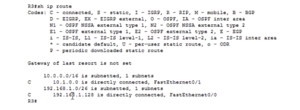
Let's get back to our network 192.168.1.0/24. Router 3 tells router 4 about the whole network 1.0, as indicated by / 24. This means that all 256 IP addresses of this network, including the network identifier and broadcast address, are available, that is, messages from devices with any IP address in this range will be sent via network 10.1.1.1. Let's look at the routing table R3.
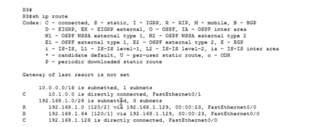
We see a network 192.168.1.0/26, divided into 3 subnets. This means that the router knows only about the three specified IP addresses: 192.168.1.0, 192.168.1.64 and 192.168.1.128, which belong to the / 26 network. But he does not know anything, for example, about devices with IP addresses ranging from 192.168.1.192 to 192.168.1.225.
However, for some reason, R4 thinks that it knows everything about the traffic that R3 sends to it, that is, about all the IP addresses of the network 192.168.1.0/24, which is completely wrong. At the same time, routers can start dropping traffic, because they “deceive” each other - after all, router 3 has no right to tell the fourth router that it knows everything about the subnets of this network. This is due to a problem called auto-summation. It occurs when traffic flows on different large networks. For example, in our case, a network with class C addresses is connected through an R3 router to a network with class A addresses.
The R3 router considers these networks the same and automatically summarizes all routes into a single network address 192.168.1.0. Recall that we talked about summing the routes of supernets in one of the previous videos. The reason for the summation is simple - the router believes that one entry in the routing table, we have this entry 192.168.1.0/24 [120/1] via 10.1.1.1, is better than 3 entries. If the network consists of hundreds of small subnets, then when the summarization is disabled, the routing table will consist of a huge number of routing entries.Therefore, to prevent the accumulation of a huge amount of information in the routing tables, automatic route summation is used.
However, in our case, auto-summing of routes creates a problem, since it forces the router to exchange false information. Therefore, we need to go into the settings of the R3 router and enter a command that prohibits auto-summarization of routes.
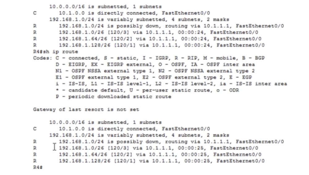
To do this, I type the router rip and no auto-summary commands in sequence. After that, you need to wait until the update is distributed over the network, and then you can use the show ip route command in the settings of the R4 router.
, . 192.168.1.0/24 [120/1] via 10.1.1.1 , , Update 30 . Flush , 240 30 , 270 , .
192.168.1.0/26, 192.168.1.64/26 192.168.1.128/26 , , 192.168.1.225, , , . , R3, 10.1.1.1, , R3 , .
, . , R3. – , , .
RIP Loops, . , . 192.168.1.0/24, . , . , , .. – , .
RIP , . - Loops, « ».
, – 1 2 N2, 1 N1, 2 – N3. , - N1-R1 .

2 , N1 1, . , 1 Hold Down . 2 Update, 1 , , N1 . 1 , 2 N1.
, 1 : « , N1, , - , 2 , . , , 2 , , N1 2 !».
, 2 : «, R1, , N1 . , 3 . , - , , , ». R2 , , N1 4 .
, ? , , . RIP 16, , , . RIP. , RIP – - , , . 1969 , , , - , RIP . , , , OSPF. - . .
We will no longer return to RIP, therefore, using the example of this oldest network protocol, I have sufficiently told you about the basics of routing and the problems that make it impossible to use this protocol for large networks anymore. In the following video tutorials, we will look at modern routing protocols - OSPF and EIGRP.
Thank you for staying with us. Do you like our articles? Want to see more interesting materials? Support us by placing an order or recommending it to your friends, a 30% discount for Habr users on a unique analogue of entry-level servers that we invented for you: The whole truth about VPS (KVM) E5-2650 v4 (6 Cores) 10GB DDR4 240GB SSD 1Gbps from $ 20 or how to divide the server? (options are available with RAID1 and RAID10, up to 24 cores and up to 40GB DDR4).
Dell R730xd 2 times cheaper? Only we have 2 x Intel TetraDeca-Core Xeon 2x E5-2697v3 2.6GHz 14C 64GB DDR4 4x960GB SSD 1Gbps 100 TV from $ 199 in the Netherlands! Dell R420 - 2x E5-2430 2.2Ghz 6C 128GB DDR3 2x960GB SSD 1Gbps 100TB - from $ 99! Read about How to Build Infrastructure Bldg. class c using Dell R730xd E5-2650 v4 servers costing 9,000 euros for a penny?
Today we will consider 3 aspects: understanding of the work and setting up RIP in routers, RIP timers, RIP restrictions. This protocol was created in 1969, so it is one of the oldest network protocols. Its advantage lies in its extraordinary simplicity. Today, many network devices, including Cisco, continue to support RIP, because it is not proprietary like EIGRP, but a public protocol.
There are 2 versions of RIP. The first, classic version does not support VLSM - the variable length of the subnet mask on which classless IP addressing is based, so we can use only one network. I will talk about this a little later. This version also does not support authentication.
Suppose you have 2 routers connected to each other. In this case, the first router tells the neighbor everything that he knows. Suppose network 10 is connected to the first router, network 20 is located between the first and second router, and network 30 is located behind the second router. Then the first router tells the second that it knows networks 10 and 20, and router 2 tells router 1 that it knows about network 30 and network 20.
The routing protocol indicates that these two networks need to be added to the routing table. In general, it turns out that one router talks about the networks connected to it to a neighboring router, one to its neighbor, etc. Simply put, RIP is a gossip protocol that serves to ensure that neighboring routers share information with each other, and each of the neighbors unconditionally believes what they told him. Each router “listens” for changes in the network and shares them with its neighbors.
The lack of authentication support means that any router that will be connected to the network immediately becomes its full member. If I want to bring down the network, I will connect my hacker router with malicious updates to it, and since all other routers trust it, they will update their routing tables as I need. Against such a hack, the first version of RIP does not provide any protection.
RIPv2 can provide authentication by configuring the router accordingly. In this case, updating information between routers will become possible only after passing through network authentication by entering a password.
RIPv1 uses Broadcasting, that is, all updates are sent using broadcast messages, so that they are received by all network participants. Suppose a computer is connected to the first router that does not know anything about these updates, since only routing devices need them. However, router 1 will send these messages to all devices that have a Broadcast ID, that is, even to those who do not need it.
In the second version of RIP, this problem is solved - it uses Multicast ID, or multicast traffic. In this case, only those devices that are specified in the protocol settings receive updates. In addition to authentication, this version of RIP supports classless VLSM IP addressing. This means that if a 10.1.1.1/24 network is connected to the first router, then all network devices whose IP address is in the address range of this subnet also receive updates. The second version of the protocol supports the CIDR method, that is, when the second router receives the update, it knows which particular network or route it is concerned. In the case of the first version, if a 10.1.1.0 network is connected to the router, then devices of the 10.0.0.0 network and other networks belonging to the same class will also receive updates. At the same time, router 2 will also receive complete information about updating these networks, however, without CIDR, it will not know that this information concerns a subnet with class A IP addresses.
This is what RIP is in very general terms. Now let's look at how it can be configured. You need to go into global configuration mode of the router settings and use the Router RIP command.
After that, you will see that the command line header has changed to R1 (config-router) #, because we have moved to the sub-command level of the router. The second command will be Version 2, that is, we tell the router that it should use version 2 of the protocol. Next, we must enter the address of the announced class network through which updates should be transmitted using the network XXXX command. This command has 2 functions: first, it indicates which network should be announced, and second, which interface should be used for this. You will understand what I mean when you look at the network configuration.
Here we have 4 routers and a computer connected to the switch through a network with the identifier 192.168.1.0/26, which is divided into 4 subnets. We use only 3 subnets: 192.168.1.0/26, 192.168.1.64/26 and 192.168.1.128/26. We still have the 192.168.1.192/26 subnet, but it is not used due to uselessness.
The device ports have the following IP addresses: computer 192.168.1.10, first port of the first router 192.168.1.1, second port 192.168.1.65, first port of the second router 192.168.1.66, second port of the second router 192.168.1.129, first port of the third router 192.168.1.130 . Last time we talked about agreements, so I can’t follow the convention and assign the address .1 to the second port of the router, because .1 is not part of this network.
Further, I use other addresses, because we start another network - 10.1.1.0/16, so the second port of the second router to which this network is connected has the IP address 10.1.1.1, and the port of the fourth router to which the switch is connected - address 10.1.1.2.
In order to configure the network I created, I must assign IP addresses to the devices. Let's start with the first port of the first router.
First, create the host name R1, assign the address 192.168.1.1 to the port f0 / 0 and specify the subnet mask 255.255.255.192, since we have a network of the form / 26. We complete the configuration of R1 with the no shut command. The second port of the first f0 / 1 router will receive the IP address 192.168.1.65 and the subnet mask 255.255.255.192.
The second router will receive the name R2, the first port f0 / 0 we will assign the address 192.168.1.66 and the subnet mask 255.255.255.192, the second port f0 / 1 - the address 192.168.1.129 and the subnet mask 255.255.255.192.
Moving to the third router, we will assign it the host name R3, port f0 / 0 will receive the address 192.168.1.130 and mask 255.255.255.192, and port f0 / 1 will receive the address 10.1.1.1 and mask 255.255.0.0, because this network is / 16.
Finally, I will go to the last router, give it the name R4 and assign the address 10.1.1.2 and the mask 255.255.0.0 to the port f0 / 0. So, we configured all network devices.
Finally, let's look at the network settings of the computer - it has a static IP address of 192.168.1.10, a half-net mask of 255.255.255.192, and the default gateway address is 192.168.1.1.
So, you saw how the subnet mask is configured for devices in different subnets, it is very simple. Now enable routing. I go into the settings of R1, set the global configuration mode and type the router command. After that, the system gives hints of possible routing protocols for this command: bgp, eigrp, ospf, and rip. Since our tutorial is about RIP, I use the router rip command.
If you type a question mark, the system will give a new hint for the following command with possible options for the functions of this protocol: auto-summary - automatic route summarization, default-information - control of the default information presentation, network - networks, timings, and so on. Here you can select the information that we will exchange with neighboring devices. The most important function is the version, so we will start by entering the version 2 command. Next, we need to use the key network command, which creates the route for the specified IP network.
We will continue to configure Router1 later, and now I want to go to router 3. Before I use the network command for it, let's look at the right side of our network topology. The second port of the router has the address 10.1.1.1. How does RIP work? Even in the second version of RIP, as a rather old protocol, it still uses its own network classes. Therefore, despite the fact that our network 10.1.1.0/16 belongs to class A, we must specify the full version of the class of this IP address using the network 10.0.0.0 command.
But even if I type the network 10.1.1.1 command and then look at the current configuration, I will see that the system fixed 10.1.1.1 to 10.0.0.0, automatically using the full-class addressing format. So if you have a question about RIP in the CCNA exam, you will need to use full-class addressing. If instead of 10.0.0.0 you type 10.1.1.1 or 10.1.0.0, then make an error. Despite the fact that conversion to a full-class addressing form occurs automatically, I advise you to use the correct address initially so that you don’t have to wait until the system corrects the error. Remember - RIP always uses full-class network addressing.
After you use the network 10.0.0.0 command, the third router will insert this tenth network into the routing protocol and send the update along the R3-R4 route. Now you need to configure the routing protocol of the fourth router. I go into its settings and enter the router rip, version 2 and network 10.0.0.0 commands sequentially. With this command, I ask R4 to start announcing network 10. using the RIP routing protocol.
Now these two routers could exchange information, but that would not change anything. Using the show ip route command shows that FastEthernrt 0/0 is directly connected to the 10.1.0.0 network. The fourth router, having received the announcement of the network from the third router, will say: "Fine, buddy, I received your announcement of the tenth network, but I already know about it because I am directly connected to this network."
Therefore, we will return to the settings of R3 and insert another network with the network 192.168.1.0 command. I am using the full-class addressing format again. After that, the third router will be able to announce the network 192.168.1.128 along the route R3-R4. As I already said, RIP is a “gossip” that talks about new networks to all its neighbors, passing them information from its routing table. If you now look at the table of the third router, you can see the data of two networks connected to it.
He will transmit this data to both ends of the route to both the second and fourth routers. Let's move on to the R2 settings. I enter the same router rip, version 2, and network 192.168.1.0 commands, and here the fun begins. I am specifying a network of 1.0, but this is both the network 192.168.1.64/26 and the network 192.168.1.128/26. Therefore, when I specify the network 192.168.1.0, I technically provide routing for both interfaces of this router. Convenience is that with just one command you can specify routing for all ports of the device.
I specify the exact same parameters for the R1 router and in the same way I provide routing for both interfaces. If you now look at the routing table R1, you can see all the networks.
This router knows about network 1.0 and network 1.64. He also knows about networks 1.128 and 10.1.1.0, because he uses RIP. This is indicated by the heading R in the corresponding row of the routing table.
I ask you to pay attention to the information [120/2] - this is the administrative distance, that is, the reliability of the source of routing information. This value may have a larger or smaller value, but by default it is 120 for the RIP protocol. For example, a static route has an administrative distance of 1. The smaller the administrative distance, the more reliable the protocol. If the router will be able to choose between two protocols, for example between a static route and RIP, then it will choose to forward traffic along the static route. The second value in parentheses, / 2, is the metric. In the RIP protocol, the metric means the number of hopes. In this case, the network 10.0.0.0/8 can be reached in 2 hop, that is, the R1 router should send traffic over the network 192.168.1.64/26, this is the first hop, and over the network 192.168.1.128/26, this is the second hop to get to the network 10.0.0.0/8 through a device with FastEthernet 0/1 interface with an IP address of 192.168.1.66.
For comparison, the R1 router can reach the network 192.168.1.128 with an administrative distance of 120 per 1 hop through the interface 192.168.1.66.
Now, if you try to ping the interface of the R4 router with the IP address 10.1.1.2 from PC0, it will successfully return.
The first attempt failed with the Request timed out message, because when using ARP, the first packet disappears, but the other three successfully returned to the destination. In this way, peer-to-peer communication occurs on a network using the RIP routing protocol.
So, in order to activate the use of the RIP protocol by the router, you need to type the router rip, version 2 and network <network number / network identifier in full-class form> commands in sequence.
We go into the settings of R4 and enter the command show ip route. You see that network 10. is connected directly to the router, and network 192.168.1.0/24 is accessible through port f0 / 0 with IP address 10.1.1.1 via RIP protocol.
If you pay attention to the type of network 192.168.1.0/24, you will notice that there is a problem of auto-summing of routes. If auto-summarization is enabled, the RIP protocol will summarize all networks up to 192.168.1.0/24. Let's look at what timers are. RIP has 4 basic timers.
The Update timer is responsible for the frequency of sending updates, every 30 seconds sending protocol updates on all interfaces involved in RIP routing. This means that he takes the routing table and sends it to all ports operating in RIP mode.
Imagine that we have router 1, which is connected to router 2 by network N2. Before the first and after the second router there are networks N1 and N3. Router 1 tells router 2 that it knows the network N1 and N2, and sends it an update. Router 2 tells router 1 that it knows the networks N2 and N3. At the same time, every 30 seconds, the ports of the routers exchange routing tables.
Imagine, for some reason, the N1-R1 connection has broken and Router 1 can no longer connect to the N1 network. After that, the first router will only send updates to the second router regarding the N2 network. Router 2, having received the first such update, will think: “excellent, now I have to put the N1 network in the Invalid Timer network timer”, and then start the Invalid timer. For 180 seconds, he will not exchange updates with the N1 network with anyone, but after this period of time, he stops Invalid Timer and starts Update Timer again. If during these 180 seconds he does not receive any status updates for the N1 network, he will place it in the Hold Down timer for 180 seconds, that is, the Hold Down timer starts immediately after the Invalid timer ends.
At the same time, another, fourth Flush timer is running, which starts simultaneously with the Invalid timer. This timer determines the time interval between the receipt of the last normal update about the N1 network until this network is excluded from the routing table. Thus, when the duration of this timer reaches 240 seconds, network N1 is automatically excluded from the routing table of the second router.
So, Update Timer sends updates every 30 seconds. Invalid Timer, which starts every 180 seconds, waits until a new update reaches the router. If it does not arrive, it puts the network on hold, with the Hold Down Timer starting every 180 seconds. But Invalid and Flush timers start at the same time, so that 240 seconds after Flush starts, a network that is not mentioned in the update is excluded from the routing table. The duration of these timers is set by default and can be changed. This is what RIP timers are.
Now let's move on to the limitations of the RIP protocol, there are quite a few of them. One of the main limitations is autosumming.
Let's get back to our network 192.168.1.0/24. Router 3 tells router 4 about the whole network 1.0, as indicated by / 24. This means that all 256 IP addresses of this network, including the network identifier and broadcast address, are available, that is, messages from devices with any IP address in this range will be sent via network 10.1.1.1. Let's look at the routing table R3.
We see a network 192.168.1.0/26, divided into 3 subnets. This means that the router knows only about the three specified IP addresses: 192.168.1.0, 192.168.1.64 and 192.168.1.128, which belong to the / 26 network. But he does not know anything, for example, about devices with IP addresses ranging from 192.168.1.192 to 192.168.1.225.
However, for some reason, R4 thinks that it knows everything about the traffic that R3 sends to it, that is, about all the IP addresses of the network 192.168.1.0/24, which is completely wrong. At the same time, routers can start dropping traffic, because they “deceive” each other - after all, router 3 has no right to tell the fourth router that it knows everything about the subnets of this network. This is due to a problem called auto-summation. It occurs when traffic flows on different large networks. For example, in our case, a network with class C addresses is connected through an R3 router to a network with class A addresses.
The R3 router considers these networks the same and automatically summarizes all routes into a single network address 192.168.1.0. Recall that we talked about summing the routes of supernets in one of the previous videos. The reason for the summation is simple - the router believes that one entry in the routing table, we have this entry 192.168.1.0/24 [120/1] via 10.1.1.1, is better than 3 entries. If the network consists of hundreds of small subnets, then when the summarization is disabled, the routing table will consist of a huge number of routing entries.Therefore, to prevent the accumulation of a huge amount of information in the routing tables, automatic route summation is used.
However, in our case, auto-summing of routes creates a problem, since it forces the router to exchange false information. Therefore, we need to go into the settings of the R3 router and enter a command that prohibits auto-summarization of routes.
To do this, I type the router rip and no auto-summary commands in sequence. After that, you need to wait until the update is distributed over the network, and then you can use the show ip route command in the settings of the R4 router.
, . 192.168.1.0/24 [120/1] via 10.1.1.1 , , Update 30 . Flush , 240 30 , 270 , .
192.168.1.0/26, 192.168.1.64/26 192.168.1.128/26 , , 192.168.1.225, , , . , R3, 10.1.1.1, , R3 , .
, . , R3. – , , .
RIP Loops, . , . 192.168.1.0/24, . , . , , .. – , .
RIP , . - Loops, « ».
, – 1 2 N2, 1 N1, 2 – N3. , - N1-R1 .
2 , N1 1, . , 1 Hold Down . 2 Update, 1 , , N1 . 1 , 2 N1.
, 1 : « , N1, , - , 2 , . , , 2 , , N1 2 !».
, 2 : «, R1, , N1 . , 3 . , - , , , ». R2 , , N1 4 .
, ? , , . RIP 16, , , . RIP. , RIP – - , , . 1969 , , , - , RIP . , , , OSPF. - . .
We will no longer return to RIP, therefore, using the example of this oldest network protocol, I have sufficiently told you about the basics of routing and the problems that make it impossible to use this protocol for large networks anymore. In the following video tutorials, we will look at modern routing protocols - OSPF and EIGRP.
Thank you for staying with us. Do you like our articles? Want to see more interesting materials? Support us by placing an order or recommending it to your friends, a 30% discount for Habr users on a unique analogue of entry-level servers that we invented for you: The whole truth about VPS (KVM) E5-2650 v4 (6 Cores) 10GB DDR4 240GB SSD 1Gbps from $ 20 or how to divide the server? (options are available with RAID1 and RAID10, up to 24 cores and up to 40GB DDR4).
Dell R730xd 2 times cheaper? Only we have 2 x Intel TetraDeca-Core Xeon 2x E5-2697v3 2.6GHz 14C 64GB DDR4 4x960GB SSD 1Gbps 100 TV from $ 199 in the Netherlands! Dell R420 - 2x E5-2430 2.2Ghz 6C 128GB DDR3 2x960GB SSD 1Gbps 100TB - from $ 99! Read about How to Build Infrastructure Bldg. class c using Dell R730xd E5-2650 v4 servers costing 9,000 euros for a penny?
All Articles