Training Cisco 200-125 CCNA v3.0. Day 18. Routing Basics
Today we will begin to study routers. If you went through my video course from the first to the 17th lesson, then you have already learned the basics of switches. Now we are moving on to the next device - the router. As you know from the previous video tutorial, one of the topics of the CCNA course is called Cisco Switching & Routing.
In this series, we will not study Cisco routers, but consider the concept of routing as a whole. We will have three topics. The first is an overview of what you already know about routers and a conversation about how this can be applied in conjunction with the knowledge you gained in the process of studying switches. We need to understand what the joint work of switches and routers consists of.
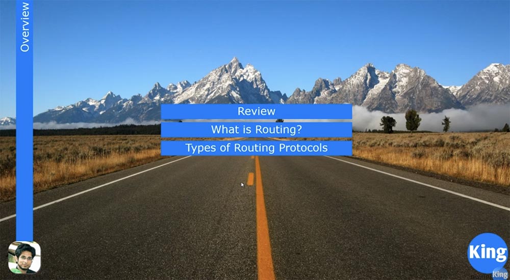
Next, we look at what routing is, what it means and how it works, and then move on to the types of routing protocols. Today I am using the topology that you have already seen in previous lessons.
We looked at how data travels across the network and how a three-step TCP handshake is made. The first message sent over the network is a SYN packet. Let's look at how a three-stage handshake occurs when a computer with an IP address 10.1.1.10 wants to contact the server 30.1.1.10, that is, it tries to establish an FTP connection.
In order to start the connection, the computer creates a source port with a random number 25113. If you forget how this happens, I advise you to review the previous video tutorials that addressed this issue.
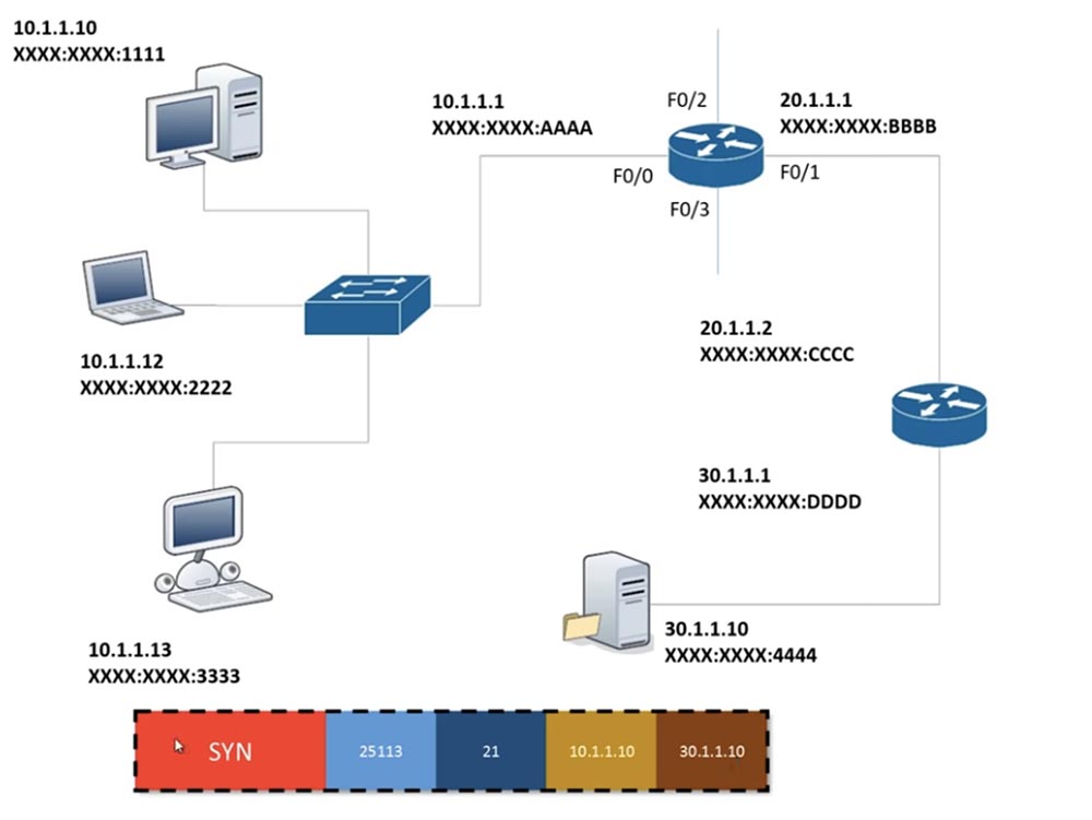
Then he puts the destination port number in the frame, because he knows that he needs to connect to port 21, then he adds the third-level OSI information, that is, his own IP address and the IP address of the destination. Dotted data does not change until it reaches the endpoint. Having reached the server, they also do not change, but the server adds to the frame information of the second level, that is, the MAC address. This is due to the fact that switches only accept OSI second level information. In this scenario, the router is the only network device that considers information of the 3rd level, of course, the computer also works with this information. So, the switch works only with information of the 2nd level, and the router - of the 3rd.
The switch knows the source MAC address XXXX: XXXX: 1111 and wants to know the MAC address of the server that the computer is accessing. He compares the source IP address with the destination address, understands that these devices are located on different subnets, and decides to use a gateway to go to another subnet.
I am often asked who decides what the IP address of the gateway should be. First, it is up to the network administrator to create the network and provide an IP address for each device. As an administrator, you can assign to the router any address that is in the range of allowed addresses of your subnet. Usually this is the first or last valid address, but there are no strict rules regarding its purpose. In our case, the administrator assigned the address of the gateway, or router, 10.1.1.1 and assigned it to port F0 / 0.
When you configure the network on a computer with a static IP address of 10.1.1.10, you assign a subnet mask of 255.255.255.0 and a default gateway of 10.1.1.1. If you do not use a static address, then the computer uses DHCP, which assigns a dynamic address. Regardless of which IP address the computer uses, static or dynamic, a gateway address must be present to access another network.
Thus, the computer 10.1.1.10 knows that it must send the frame to the router 10.1.1.1. This transfer takes place inside the local network, where the IP address does not matter, only the MAC address is important here. Suppose that the computer had never contacted the router before and did not know its MAC address, so it must first send an ARP request, which asks all the devices on the subnet: “hey, which of you has the address 10.1.1.1? Please tell me your MAC address! ” Since ARP is a broadcast message, it arrives at all ports of all devices, including the router.
The computer 10.1.1.12, having received the ARP, thinks: “no, my address is not 10.1.1.1”, and rejects the request, the computer 10.1.1.13 does the same. The router, having received the request, understands that they are asking for it, and sends the MAC address of the port F0 / 0 - and all ports have a different MAC address - to the computer 10.1.1.10. Now, knowing the gateway address XXXX: AAAA, which in this case is the destination address, the computer adds it to the end of the frame addressed to the server. Along with this, he sets the header of the FCS / CRC frame, which is a mechanism for checking transmission errors.
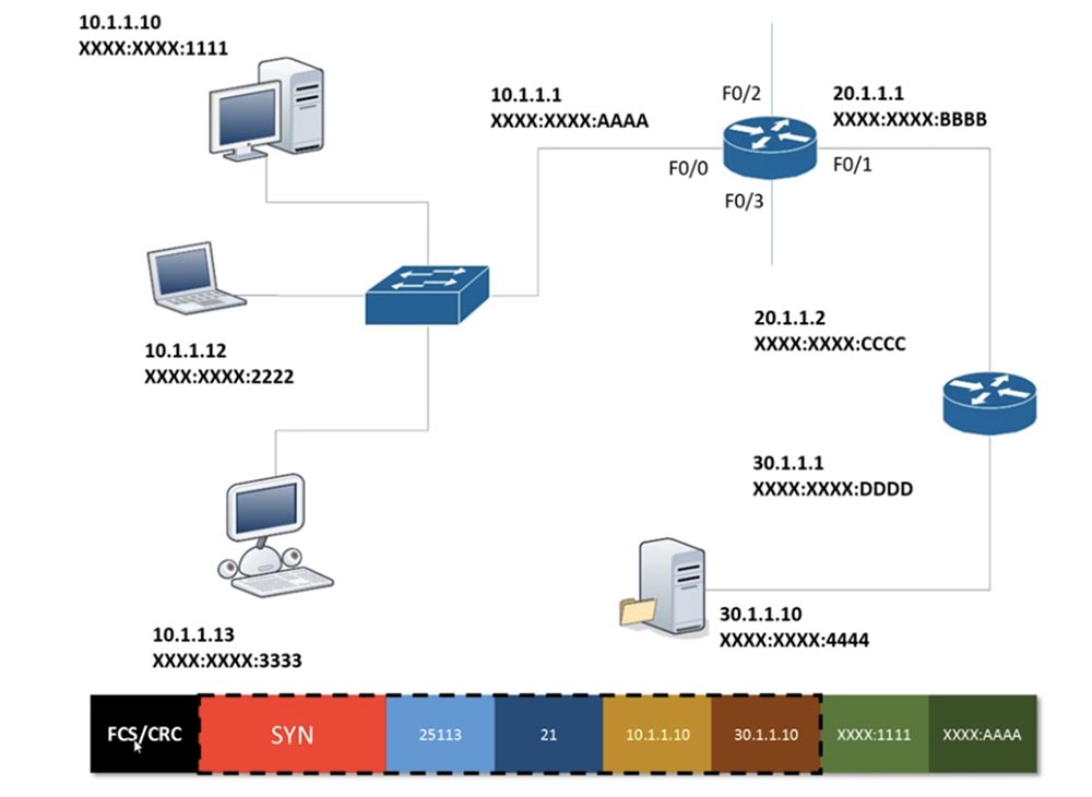
After that, the frame of the computer 10.1.1.10 is sent by wire to the router 10.1.1.1. After receiving the frame, the router deletes FCS / CRC using the same algorithm as the computer for verification. Data is nothing more than a collection of zeros and ones. If the data is damaged, that is, 1 becomes 0 or 0 becomes one, or there is a data leak that often occurs when using the hub, then the device must forward the frame again.
If the FCS / CRC check is successful, the router looks at the source and destination MAC addresses and deletes them, since this is level 2 information, and goes to the body of the frame, which contains level 3 information. From it, he learns that the information that the frame contains is for a device with an IP address of 30.1.1.10.
The router somehow knows where this device is located. We did not discuss this issue when we considered the operation of switches, so we will consider it now. The router has 4 ports, so I added a few more connections to it. So, how does the router know that the data for the device with the IP address 30.1.1.10 needs to be sent through port F0 / 1? Why doesn't he send them through port F0 / 3 or F0 / 2?
The fact is that the router works with a routing table. Each router has a table that allows you to decide which port to transmit a particular frame through.

In this case, port F0 / 0 is configured to the IP address 10.1.1.1 and this means that it is connected to the network 10.1.1.10/24. Similarly, port F0 / 1 is configured to address 20.1.1.1, that is, it is connected to a network 20.1.1.0/24. The router knows both of these networks because they are directly connected to its ports. Thus, the information that traffic for the 10.1.10 / 24 network should go through the F0 / 0 port, and for the 20.1.1.0/24 network should go through the F0 / 1 port, is known by default. How does the router know through which ports to work with other networks?
We see that network 40.1.1.0/24 is connected to port F0 / 2, network 50.1.1.0/24 is connected to port F0 / 3, and network 30.1.1.0/24 connects the second router to the server. The second router also has a routing table, which says that the network 30. is connected to its port, we denote it 0/1, and it is connected to the first router through port 0/0. This router knows that its port 0/0 is connected to network 20., and port 0/1 is connected to network 30., and knows nothing more.
Similarly, the first router knows about networks 40. and 50. connected to ports 0/2 and 0/3, but does not know anything about network 30. The routing protocol provides routers with information that they do not own by default. The mechanism by which these routers interact with each other is the basis of routing, and there is dynamic and static routing.
Static routing is that the first router is given information: if you need to contact the network 30.1.1.0/24, then you need to use port F0 / 1. However, when the second router receives traffic from a server that is designed for computer 10.1.1.10, he does not know what to do with it, because in his routing table there is only information about network 30. and 20. Therefore, this router also needs to register static routing : if it receives traffic for network 10., then it should send it through port 0/0.
The problem with static routing is that I have to manually configure the first router to work with network 30. and the second router to work with network 10. This is simple if I have only 2 routers, but when I have 10 routers, setting up static Routing takes a lot of time. In this case, it makes sense to use dynamic routing.
So, having received the frame from the computer, the first router looks at its routing table and decides to send it through port F0 / 1. At the same time, it adds the source MAC address XXXX.BBBB and the destination MAC address XXXX.SSCC to the frame.
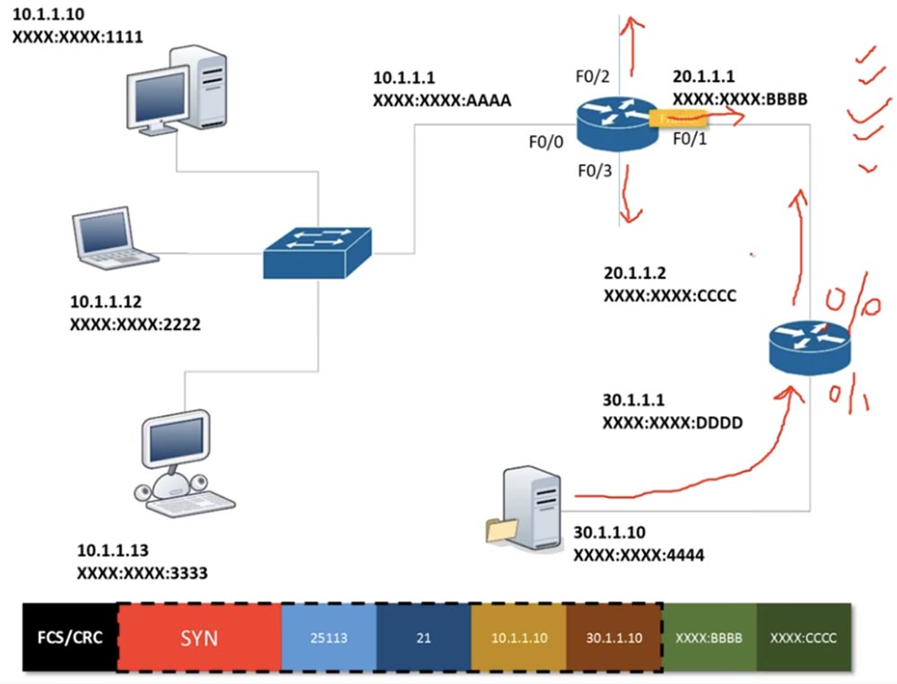
Having received this frame, the second router "cuts off" the MAC addresses related to the second level of OSI, and goes to the information of the third level. He sees that the destination IP address 30.1.1.10 belongs to the same network as the port 0/1 of the router, adds the source MAC address and the MAC address of the destination device to the frame and sends the frame to the server.

As I already said, then a similar process is repeated in the opposite direction, that is, the second handshake stage is carried out, in which the server sends back a SYN ACK message. Before that, it discards all unnecessary information and leaves only the SYN packet.

Having received this packet, the second router considers the information received, supplements it and sends it further.
So, in the previous lessons, we studied how the switch works, and now we learned how routers work. Let's answer the question of what routing is in a global sense. Suppose you come across a signpost installed at a roundabout. You see that the first branch leads to the Royal Air Force Fairfax base, the second to the airport, the third to the south. If you choose the fourth exit, you will end up in a dead end, and through the fifth you can drive through the city center to Braxby Castle.

In general, routing is what makes the router decide where to direct traffic. In this case, you, as a driver, must decide which exit from the intersection you need to take. In networks, routers have to make decisions where to send packets or frames. You must understand that routing allows you to create tables on the basis of which routers make these decisions.
As I said, there is static and dynamic routing. Consider static routing, for which I will draw 3 devices connected to each other, with the first and third devices connected to networks. Suppose that one network 10.1.1.0 wants to connect to network 40.1.1.0, and between routers there are networks 20.1.1.0 and 30.1.1.0.

In this case, the ports of the routers should belong to different subnets. Router 1 by default only knows about network 10. and 20. and knows nothing about other networks. Router 2 only knows about networks 20. and 30. because they are connected to it, and router 3 only knows about networks 30. and 40. If network 10. wants to connect to network 40., I have to tell router 1 about network 30 . and that if he wants to transfer the frame of network 40., he must use the interface for network 20. and send the frame over the same network 20.
I have to assign 2 routes to the second router: if he wants to transfer the packet from network 40. to network 10., he must use network port 20., and to transfer the packet from network 10. network 40. - network port 30. Similarly, I must provide router 3 with information about networks 10. and 20.
If you have small networks, then static routing is very easy to configure. However, the more the network grows, the more problems arise with static routing. Imagine that you created a new connection that directly connects the first and third routers. In this case, the dynamic routing protocol will automatically update the routing table of router 1, indicating the following: “if you need to contact router 3, use a direct route”!

There are two types of routing protocols: IGP Internal Gateway Protocol and EGP External Gateway Protocol. The first protocol works with a separate, autonomous system known as a routing domain. Imagine that you have a small organization with only 5 routers. If we are only talking about the connection between these routers, we mean IGP, but if you use your network to connect to the Internet, as ISP providers do, then use EGP.

IGP uses 3 popular protocols: RIP, OSPF and EIGRP. The CCNA curriculum only mentions the last two protocols because RIP is deprecated. This is the simplest of the routing protocols, which is still used in some cases, but does not provide the necessary network security. This is one of the reasons Cisco excluded RIP from the course. However, I will still tell you about it, because learning it helps to understand the basics of routing.
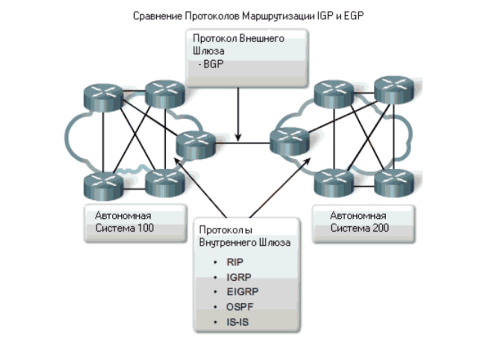
The classification of EGP protocols uses two protocols: BGP and the actual EGP protocol. In studying the CCNA course, we will only consider BGP, OSPF, and EIGRP. You can consider the story about RIP bonus information, which will be reflected in one of the video tutorials.
There are 2 more types of routing protocols: distance vector distance vector protocols and Link State link state routing protocols.

The first puncture considers the distance and direction vectors. For example, I can connect directly between R1 and R4, or I can connect along the path R1-R2-R3-R4. If we are talking about routing protocols using the remote vector method, then in this case the connection will always be carried out along the shortest path. It does not matter that this connection will have a minimum speed. In our case, it is 128 kbps, which is much slower than the connection along the route R1-R2-R3-R4, where the speed is 100 mbps.
Consider the distance-vector protocol RIP. I will finish network 10 in front of R1, and network 40 behind R4. Suppose that there are many computers in these networks. If I want to make a connection between network 10. R1 and network 40. R4, then I will assign R1 static routing of the type: “if you need to connect to network 40., use a direct connection with router R4”. At the same time, on all 4 routers, I must manually configure RIP. Then the routing table R1 will automatically report that if network 10. wants to connect to network 40., you must use a direct connection R1-R4. Even if the workaround is faster, the Distance Vector protocol will still select the shortest path with the smallest transmission distance.
OSPF is a channel state routing protocol that always looks at the state of network sections. In this case, he estimates the speed of the channels, and if he sees that the transmission rate of traffic on the channel R1-R4 is very low, he chooses a path with a higher speed R1-R2-R3-R4, even if its length exceeds the shortest path. Thus, if I configure OSPF protocol on all routers, when I try to connect network 40. to network 10., traffic will be sent along the route R1-R2-R3-R4. So, RIP is a distance vector protocol, and OSPF is a channel state routing protocol.
There is another protocol - EIGRP, Cisco's proprietary routing protocol. If we talk about network devices from other manufacturers, for example, Juniper, then they do not support EIGRP. This is an excellent routing protocol that is much more efficient than RIP and OSPF, but it can only be used on networks based on Cisco devices. Later I will tell you more about why this protocol is so good. So far, I note that EIGRP combines the features of distance-vector protocols and channel state routing protocols, representing a hybrid protocol.
In the next video tutorial, we will come close to examining Cisco routers; I will tell you a little about the Cisco IOS operating system, which is designed for both switches and routers. I hope that in the lessons of the 19th or 20th day we will begin a detailed study of the routing protocols, and I will show how to configure Cisco routers using the example of small networks.
Thank you for staying with us. Do you like our articles? Want to see more interesting materials? Support us by placing an order or recommending it to your friends, a 30% discount for Habr users on a unique analogue of entry-level servers that we invented for you: The whole truth about VPS (KVM) E5-2650 v4 (6 Cores) 10GB DDR4 240GB SSD 1Gbps from $ 20 or how to divide the server? (options are available with RAID1 and RAID10, up to 24 cores and up to 40GB DDR4).
Dell R730xd 2 times cheaper? Only we have 2 x Intel TetraDeca-Core Xeon 2x E5-2697v3 2.6GHz 14C 64GB DDR4 4x960GB SSD 1Gbps 100 TV from $ 199 in the Netherlands! Dell R420 - 2x E5-2430 2.2Ghz 6C 128GB DDR3 2x960GB SSD 1Gbps 100TB - from $ 99! Read about How to Build Infrastructure Bldg. class c using Dell R730xd E5-2650 v4 servers costing 9,000 euros for a penny?
In this series, we will not study Cisco routers, but consider the concept of routing as a whole. We will have three topics. The first is an overview of what you already know about routers and a conversation about how this can be applied in conjunction with the knowledge you gained in the process of studying switches. We need to understand what the joint work of switches and routers consists of.
Next, we look at what routing is, what it means and how it works, and then move on to the types of routing protocols. Today I am using the topology that you have already seen in previous lessons.
We looked at how data travels across the network and how a three-step TCP handshake is made. The first message sent over the network is a SYN packet. Let's look at how a three-stage handshake occurs when a computer with an IP address 10.1.1.10 wants to contact the server 30.1.1.10, that is, it tries to establish an FTP connection.
In order to start the connection, the computer creates a source port with a random number 25113. If you forget how this happens, I advise you to review the previous video tutorials that addressed this issue.
Then he puts the destination port number in the frame, because he knows that he needs to connect to port 21, then he adds the third-level OSI information, that is, his own IP address and the IP address of the destination. Dotted data does not change until it reaches the endpoint. Having reached the server, they also do not change, but the server adds to the frame information of the second level, that is, the MAC address. This is due to the fact that switches only accept OSI second level information. In this scenario, the router is the only network device that considers information of the 3rd level, of course, the computer also works with this information. So, the switch works only with information of the 2nd level, and the router - of the 3rd.
The switch knows the source MAC address XXXX: XXXX: 1111 and wants to know the MAC address of the server that the computer is accessing. He compares the source IP address with the destination address, understands that these devices are located on different subnets, and decides to use a gateway to go to another subnet.
I am often asked who decides what the IP address of the gateway should be. First, it is up to the network administrator to create the network and provide an IP address for each device. As an administrator, you can assign to the router any address that is in the range of allowed addresses of your subnet. Usually this is the first or last valid address, but there are no strict rules regarding its purpose. In our case, the administrator assigned the address of the gateway, or router, 10.1.1.1 and assigned it to port F0 / 0.
When you configure the network on a computer with a static IP address of 10.1.1.10, you assign a subnet mask of 255.255.255.0 and a default gateway of 10.1.1.1. If you do not use a static address, then the computer uses DHCP, which assigns a dynamic address. Regardless of which IP address the computer uses, static or dynamic, a gateway address must be present to access another network.
Thus, the computer 10.1.1.10 knows that it must send the frame to the router 10.1.1.1. This transfer takes place inside the local network, where the IP address does not matter, only the MAC address is important here. Suppose that the computer had never contacted the router before and did not know its MAC address, so it must first send an ARP request, which asks all the devices on the subnet: “hey, which of you has the address 10.1.1.1? Please tell me your MAC address! ” Since ARP is a broadcast message, it arrives at all ports of all devices, including the router.
The computer 10.1.1.12, having received the ARP, thinks: “no, my address is not 10.1.1.1”, and rejects the request, the computer 10.1.1.13 does the same. The router, having received the request, understands that they are asking for it, and sends the MAC address of the port F0 / 0 - and all ports have a different MAC address - to the computer 10.1.1.10. Now, knowing the gateway address XXXX: AAAA, which in this case is the destination address, the computer adds it to the end of the frame addressed to the server. Along with this, he sets the header of the FCS / CRC frame, which is a mechanism for checking transmission errors.
After that, the frame of the computer 10.1.1.10 is sent by wire to the router 10.1.1.1. After receiving the frame, the router deletes FCS / CRC using the same algorithm as the computer for verification. Data is nothing more than a collection of zeros and ones. If the data is damaged, that is, 1 becomes 0 or 0 becomes one, or there is a data leak that often occurs when using the hub, then the device must forward the frame again.
If the FCS / CRC check is successful, the router looks at the source and destination MAC addresses and deletes them, since this is level 2 information, and goes to the body of the frame, which contains level 3 information. From it, he learns that the information that the frame contains is for a device with an IP address of 30.1.1.10.
The router somehow knows where this device is located. We did not discuss this issue when we considered the operation of switches, so we will consider it now. The router has 4 ports, so I added a few more connections to it. So, how does the router know that the data for the device with the IP address 30.1.1.10 needs to be sent through port F0 / 1? Why doesn't he send them through port F0 / 3 or F0 / 2?
The fact is that the router works with a routing table. Each router has a table that allows you to decide which port to transmit a particular frame through.
In this case, port F0 / 0 is configured to the IP address 10.1.1.1 and this means that it is connected to the network 10.1.1.10/24. Similarly, port F0 / 1 is configured to address 20.1.1.1, that is, it is connected to a network 20.1.1.0/24. The router knows both of these networks because they are directly connected to its ports. Thus, the information that traffic for the 10.1.10 / 24 network should go through the F0 / 0 port, and for the 20.1.1.0/24 network should go through the F0 / 1 port, is known by default. How does the router know through which ports to work with other networks?
We see that network 40.1.1.0/24 is connected to port F0 / 2, network 50.1.1.0/24 is connected to port F0 / 3, and network 30.1.1.0/24 connects the second router to the server. The second router also has a routing table, which says that the network 30. is connected to its port, we denote it 0/1, and it is connected to the first router through port 0/0. This router knows that its port 0/0 is connected to network 20., and port 0/1 is connected to network 30., and knows nothing more.
Similarly, the first router knows about networks 40. and 50. connected to ports 0/2 and 0/3, but does not know anything about network 30. The routing protocol provides routers with information that they do not own by default. The mechanism by which these routers interact with each other is the basis of routing, and there is dynamic and static routing.
Static routing is that the first router is given information: if you need to contact the network 30.1.1.0/24, then you need to use port F0 / 1. However, when the second router receives traffic from a server that is designed for computer 10.1.1.10, he does not know what to do with it, because in his routing table there is only information about network 30. and 20. Therefore, this router also needs to register static routing : if it receives traffic for network 10., then it should send it through port 0/0.
The problem with static routing is that I have to manually configure the first router to work with network 30. and the second router to work with network 10. This is simple if I have only 2 routers, but when I have 10 routers, setting up static Routing takes a lot of time. In this case, it makes sense to use dynamic routing.
So, having received the frame from the computer, the first router looks at its routing table and decides to send it through port F0 / 1. At the same time, it adds the source MAC address XXXX.BBBB and the destination MAC address XXXX.SSCC to the frame.
Having received this frame, the second router "cuts off" the MAC addresses related to the second level of OSI, and goes to the information of the third level. He sees that the destination IP address 30.1.1.10 belongs to the same network as the port 0/1 of the router, adds the source MAC address and the MAC address of the destination device to the frame and sends the frame to the server.
As I already said, then a similar process is repeated in the opposite direction, that is, the second handshake stage is carried out, in which the server sends back a SYN ACK message. Before that, it discards all unnecessary information and leaves only the SYN packet.
Having received this packet, the second router considers the information received, supplements it and sends it further.
So, in the previous lessons, we studied how the switch works, and now we learned how routers work. Let's answer the question of what routing is in a global sense. Suppose you come across a signpost installed at a roundabout. You see that the first branch leads to the Royal Air Force Fairfax base, the second to the airport, the third to the south. If you choose the fourth exit, you will end up in a dead end, and through the fifth you can drive through the city center to Braxby Castle.
In general, routing is what makes the router decide where to direct traffic. In this case, you, as a driver, must decide which exit from the intersection you need to take. In networks, routers have to make decisions where to send packets or frames. You must understand that routing allows you to create tables on the basis of which routers make these decisions.
As I said, there is static and dynamic routing. Consider static routing, for which I will draw 3 devices connected to each other, with the first and third devices connected to networks. Suppose that one network 10.1.1.0 wants to connect to network 40.1.1.0, and between routers there are networks 20.1.1.0 and 30.1.1.0.
In this case, the ports of the routers should belong to different subnets. Router 1 by default only knows about network 10. and 20. and knows nothing about other networks. Router 2 only knows about networks 20. and 30. because they are connected to it, and router 3 only knows about networks 30. and 40. If network 10. wants to connect to network 40., I have to tell router 1 about network 30 . and that if he wants to transfer the frame of network 40., he must use the interface for network 20. and send the frame over the same network 20.
I have to assign 2 routes to the second router: if he wants to transfer the packet from network 40. to network 10., he must use network port 20., and to transfer the packet from network 10. network 40. - network port 30. Similarly, I must provide router 3 with information about networks 10. and 20.
If you have small networks, then static routing is very easy to configure. However, the more the network grows, the more problems arise with static routing. Imagine that you created a new connection that directly connects the first and third routers. In this case, the dynamic routing protocol will automatically update the routing table of router 1, indicating the following: “if you need to contact router 3, use a direct route”!
There are two types of routing protocols: IGP Internal Gateway Protocol and EGP External Gateway Protocol. The first protocol works with a separate, autonomous system known as a routing domain. Imagine that you have a small organization with only 5 routers. If we are only talking about the connection between these routers, we mean IGP, but if you use your network to connect to the Internet, as ISP providers do, then use EGP.
IGP uses 3 popular protocols: RIP, OSPF and EIGRP. The CCNA curriculum only mentions the last two protocols because RIP is deprecated. This is the simplest of the routing protocols, which is still used in some cases, but does not provide the necessary network security. This is one of the reasons Cisco excluded RIP from the course. However, I will still tell you about it, because learning it helps to understand the basics of routing.
The classification of EGP protocols uses two protocols: BGP and the actual EGP protocol. In studying the CCNA course, we will only consider BGP, OSPF, and EIGRP. You can consider the story about RIP bonus information, which will be reflected in one of the video tutorials.
There are 2 more types of routing protocols: distance vector distance vector protocols and Link State link state routing protocols.
The first puncture considers the distance and direction vectors. For example, I can connect directly between R1 and R4, or I can connect along the path R1-R2-R3-R4. If we are talking about routing protocols using the remote vector method, then in this case the connection will always be carried out along the shortest path. It does not matter that this connection will have a minimum speed. In our case, it is 128 kbps, which is much slower than the connection along the route R1-R2-R3-R4, where the speed is 100 mbps.
Consider the distance-vector protocol RIP. I will finish network 10 in front of R1, and network 40 behind R4. Suppose that there are many computers in these networks. If I want to make a connection between network 10. R1 and network 40. R4, then I will assign R1 static routing of the type: “if you need to connect to network 40., use a direct connection with router R4”. At the same time, on all 4 routers, I must manually configure RIP. Then the routing table R1 will automatically report that if network 10. wants to connect to network 40., you must use a direct connection R1-R4. Even if the workaround is faster, the Distance Vector protocol will still select the shortest path with the smallest transmission distance.
OSPF is a channel state routing protocol that always looks at the state of network sections. In this case, he estimates the speed of the channels, and if he sees that the transmission rate of traffic on the channel R1-R4 is very low, he chooses a path with a higher speed R1-R2-R3-R4, even if its length exceeds the shortest path. Thus, if I configure OSPF protocol on all routers, when I try to connect network 40. to network 10., traffic will be sent along the route R1-R2-R3-R4. So, RIP is a distance vector protocol, and OSPF is a channel state routing protocol.
There is another protocol - EIGRP, Cisco's proprietary routing protocol. If we talk about network devices from other manufacturers, for example, Juniper, then they do not support EIGRP. This is an excellent routing protocol that is much more efficient than RIP and OSPF, but it can only be used on networks based on Cisco devices. Later I will tell you more about why this protocol is so good. So far, I note that EIGRP combines the features of distance-vector protocols and channel state routing protocols, representing a hybrid protocol.
In the next video tutorial, we will come close to examining Cisco routers; I will tell you a little about the Cisco IOS operating system, which is designed for both switches and routers. I hope that in the lessons of the 19th or 20th day we will begin a detailed study of the routing protocols, and I will show how to configure Cisco routers using the example of small networks.
Thank you for staying with us. Do you like our articles? Want to see more interesting materials? Support us by placing an order or recommending it to your friends, a 30% discount for Habr users on a unique analogue of entry-level servers that we invented for you: The whole truth about VPS (KVM) E5-2650 v4 (6 Cores) 10GB DDR4 240GB SSD 1Gbps from $ 20 or how to divide the server? (options are available with RAID1 and RAID10, up to 24 cores and up to 40GB DDR4).
Dell R730xd 2 times cheaper? Only we have 2 x Intel TetraDeca-Core Xeon 2x E5-2697v3 2.6GHz 14C 64GB DDR4 4x960GB SSD 1Gbps 100 TV from $ 199 in the Netherlands! Dell R420 - 2x E5-2430 2.2Ghz 6C 128GB DDR3 2x960GB SSD 1Gbps 100TB - from $ 99! Read about How to Build Infrastructure Bldg. class c using Dell R730xd E5-2650 v4 servers costing 9,000 euros for a penny?
All Articles