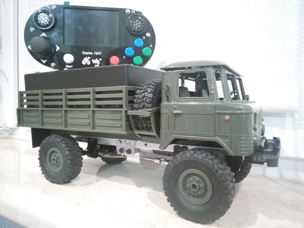
GAZ-66 toy on the control panel. Part 2
In this part we will talk about the software component, how the machine came to life. What OS were used, what language was chosen, what problems faced.
1. How it works in 2 words
The system consists of a server that is installed on a typewriter, and a client that is installed on the console. The server raises the wifi access point and waits until the client connects. The server executes client commands, and also transmits video from the camera to it.
2. OS
Now let's talk about the operating systems used.
Since the whole system is based on Raspberry pi 3 , the official OS for it was used. At the time of creation, the latest version was Stretch , it was and was selected for use on a typewriter and remote control. But it turned out that it has a bug (tormented for a week) due to which it is impossible to raise a wifi access point. Therefore, to raise the access point, a previous version of Jessie was taken that did not have such problems.
Article how to raise an access point. Very detailed, did everything on it.
The remote control automatically connects to the machine when it raises the access point.
Automatic connection to our point, in the file / etc / network / interfaces add:
auto wlan0 iface wlan0 inet dhcp wpa-ssid {ssid} wpa-psk {password}
2. Language
I chose python because it's easy and simple.
3. Server
By server in this section I will mean software written by me to control the machine and work with video.
The server consists of 2 parts. Video server and management server.
3.1 Video server
There were 2 options for working with a video camera. 1st to use picamera module and 2nd to use mjpg-streamer software . Without thinking twice, I decided to use both of them, and which one to use in the config settings.
if conf.conf.VideoServerType == 'm' : cmd = "cd /home/pi/projects/mjpg-streamer-experimental && " cmd += './mjpg_streamer -o "./output_http.so -p {0} -w ./www" -i "./input_raspicam.so -x {1} -y {2} -fps 25 -ex auto -awb auto -vs -ISO 10"'.format(conf.conf.videoServerPort, conf.conf.VideoWidth, conf.conf.VideoHeight) print(cmd) os.system(cmd) else : with picamera.PiCamera(resolution = str(conf.conf.VideoWidth) + 'x' + str(conf.conf.VideoHeight) , framerate = conf.conf.VideoRate) as Camera: output = camera.StreamingOutput() camera.output = output Camera.start_recording(output, format = 'mjpeg') try: address = (conf.conf.ServerIP, conf.conf.videoServerPort) server = camera.StreamingServer(address, camera.StreamingHandler) server.serve_forever() finally: Camera.stop_recording()
Since they take the same settings, they work at the same address. There are no problems communicating with the remote control when switching from one to another. The only thing I think mjpg-streamer works faster.
3.2 Management Server
3.2.1 Interaction between client and server
The server and client exchange commands in the form of json strings:
{'type': 'remote', 'cmd': 'Start', 'status': True, 'val': 0.0} {'type': 'remote', 'cmd': 'Y', 'status': True, 'val': 0.5} {'type': 'remote', 'cmd': 'turn', 'x': 55, 'y': 32}
- type - 'remote' or 'car' depending on who sends the command (client or server)
- cmd - a string with the name of the button corresponding to the name of the button on the Game HAT , for example:
- Start - Start button
- Select - Select button
- Y - Y button
- etc.
- turn - the command to change the state of the joystick, is responsible for turning the wheels
- status - True or False, depending on whether the button is pressed or not pressed. An event about the status of a button is dispatched every time its state changes.
- val - speed and direction of movement of the motor from -1 ... 1, value of type float . Significant parameter for motion buttons only.
- x - deviation of the joystick along the x axis from -100 ... 100, value of type int
- y - deviation of the joystick along the y axis from -100 ... 100, value of type int
Next comes my shame, to redo which hands do not reach. The machine raises the server socket and waits until the client connects to it. Moreover, for each new connection, it creates a separate stream, and each new client that will connect to the machine will be able to control it)). This can not be so far because no one else has such a remote control, and I raise my closed wifi network.
def run(self): TCP_IP = conf.conf.ServerIP TCP_PORT = conf.conf.controlServerPort BUFFER_SIZE = conf.conf.ServerBufferSize self.tcpServer = socket.socket(socket.AF_INET, socket.SOCK_STREAM) self.tcpServer.setsockopt(socket.SOL_SOCKET, socket.SO_REUSEADDR, 1) self.tcpServer.bind((TCP_IP, TCP_PORT)) threads = [] # . self.tcpServer.listen(1) while True: print("Car server up : Waiting for connections from TCP clients...") (conn, (ip, port)) = self.tcpServer.accept() newthread = ClientThread(conn, ip, port) newthread.start() self.threads.append(newthread)
3.2.2 Iron Management
When working with Raspberry, the GPIO.BCM pin numbering system was used.
The light is controlled via gpio 17, it is connected to the 2nd pin on L293 . Next, every time a command comes to include:
GPIO.output(self.gpioLight, GPIO.HIGH)
GPIO.output(self.gpioLight, GPIO.LOW)
corresponding commands are called.
The servo drive is controlled via the PCA9685 board via the I2C bus, so we need the appropriate library for it Adafruit_PCA9685 . PCA9685 is connected to the servo via 7 pin. The required PWM frequency for working with servo is 50 Hz or a period of 20 ms.
The principle of operation of the servo:

When a 1.5 ms signal is applied, the wheels will be centered. At 1 ms. the servo will turn as far as possible to the right, 2 ms. to the left as much as possible. The steering knuckles in bridges for such turns are not designed, so the angle of rotation had to be selected experimentally.
Values that can be passed to the Adafruit_PCA9685 API range from 0..4095, 0 no signal, 4095 full. Accordingly, from this range it was necessary to choose the values suitable for my wheels. The easiest way to determine the values for exactly set wheels is to transfer 1.5 ms to a value from the range of ~ 307.
The maximum value for the right is 245, for the left 369.
The values coming from the joystick take values from -100 ... 100, so they had to be translated in the range from 245 to 369. Again, the center is the easiest, if 0 it is 307. Left and right according to the formula:
val = int(HardwareSetting._turnCenter + (-1 * turn * HardwareSetting._turnDelta / HardwareSetting.yZero))
- HardwareSetting._turnCenter - 307
- turn - value from the joystick from -100 ... 100
- HardwareSetting._turnDelta - 62, the difference between the center and the maximum deviation to the side (307 - 245 = 62)
- HardwareSetting.yZero - 100, the maximum value received from the joystick
Wheels straight:
def turnCenter(self): val = int(HardwareSetting._turnCenter) self.pwm_servo.set(val) CarStatus.statusCar['car']['turn'] = val
Turn left:
def turnLeft(self, turn): val = int(HardwareSetting._turnCenter + (-1 * turn * HardwareSetting._turnDelta / HardwareSetting.yZero)) self.pwm_servo.set(val) CarStatus.statusCar['car']['turn'] = val
Turn right:
def turnRight(self, turn): val = int(HardwareSetting._turnCenter + (-1 * turn * HardwareSetting._turnDelta / HardwareSetting.yZero)) self.pwm_servo.set(val) CarStatus.statusCar['car']['turn'] = val
Engine control also takes place via the PCA9685 board via the I2C bus, so we use Adafruit_PCA9685 . Pins 10 to 15 on the PCA9685 are connected to the L298N (I use 2 channels on it to absorb power). 10 and 11 to ENA and ENB (I fill them with PWM to control the speed of movement). 12, 13, 14, 15 to IN1, IN2, IN3, IN4 - are responsible for the direction of rotation of the motor. The PWM frequency is not very important here, but I also use 50 Hertz (my default value).
The machine stands still:
def stop(self): """ . """ self.pwm.set_pwm(self.ena, 0, self.LOW) self.pwm.set_pwm(self.enb, 0, self.LOW) self.pwm.set_pwm(self.in1, 0, self.LOW) self.pwm.set_pwm(self.in4, 0, self.LOW) self.pwm.set_pwm(self.in2, 0, self.LOW) self.pwm.set_pwm(self.in3, 0, self.LOW)
Forward movement:
def back(self, speed): """ . Args: speed: 0 1. """ self.pwm.set_pwm(self.ena, 0, int(speed * self.HIGH)) self.pwm.set_pwm(self.enb, 0, int(speed * self.HIGH)) self.pwm.set_pwm(self.in1, 0, self.LOW) self.pwm.set_pwm(self.in4, 0, self.LOW) self.pwm.set_pwm(self.in2, 0, self.HIGH) self.pwm.set_pwm(self.in3, 0, self.HIGH)
Backward movement:
def forward(self, speed): """ . Args: speed: 0 1. """ self.pwm.set_pwm(self.ena, 0, int(speed * self.HIGH)) self.pwm.set_pwm(self.enb, 0, int(speed * self.HIGH)) self.pwm.set_pwm(self.in1, 0, self.HIGH) self.pwm.set_pwm(self.in4, 0, self.HIGH) self.pwm.set_pwm(self.in2, 0, self.LOW) self.pwm.set_pwm(self.in3, 0, self.LOW)
4. Customer
4.1 Keyboard
There were certain problems with her, at first I wanted to make her eventful (it took ~ 2 weeks of torment). But the mechanical buttons contributed, the rattling of the contacts led to constant and unpredictable failures (the control algorithms that I invented worked imperfectly). Then my colleague told me how the keyboards are made. And I decided to do the same, now I poll the state every 0.005 seconds (why so, and who knows). And if it has changed, send the value to the server.
def run(self): try: while True: time.sleep(0.005) for pin in self.pins : p = self.pins[pin] status = p['status'] if GPIO.input(pin) == GPIO.HIGH : p['status'] = False else : p['status'] = True if p['status'] != status : p['callback'](pin) except KeyboardInterrupt: GPIO.cleanup()
4.2 Joystick
Reading of the readings takes place via the ADS1115 board via the I2C bus, therefore, the appropriate library for it is Adafruit_PCA9685 . The joystick is also prone to chattering contacts, so I take readings from it by analogy with the keyboard.
def run(self): while True: X = self.adc.read_adc(0, gain=self.GAIN) / HardwareSetting.valueStep Y = self.adc.read_adc(1, gain=self.GAIN) / HardwareSetting.valueStep if X > HardwareSetting.xZero : X = X - HardwareSetting.xZero else : X = -1 * (HardwareSetting.xZero - X) if Y > HardwareSetting.yZero : Y = Y - HardwareSetting.yZero else : Y = -1 * (HardwareSetting.yZero - Y) if (abs(X) < 5) : X = 0 if (abs(Y) < 5) : Y = 0 if (abs(self.x - X) >= 1.0 or abs(self.y - Y) >= 1.0) : self.sendCmd(round(X), round(Y)) self.x = X self.y = Y time.sleep(0.005)
When powered by 3.3 volts, the range of values that the ADS1115 gives out with a joystick from 0 ... 26500. I bring this to the range from -100 ... 100. In my range around 0 it always fluctuates, so if the values do not exceed 5, then I consider that it is 0 (otherwise it will flood). As soon as the values change, send them to the typewriter.
4.3 Connecting to the management server
Connecting to the server is a simple thing:
try : tcpClient = socket.socket(socket.AF_INET, socket.SOCK_STREAM) tcpClient.settimeout(2.0) tcpClient.connect((conf.conf.ServerIP, conf.conf.controlServerPort)) self.signalDisplayPrint.emit("+") carStatus.statusRemote['network']['control'] = True self.tcpClient = tcpClient except socket.error as e: self.signalDisplayPrint.emit("-") carStatus.statusRemote['network']['control'] = False time.sleep(conf.conf.timeRecconect) self.tcpClient = None continue if self.tcpClient : self.tcpClient.settimeout(None)
But I want to pay attention to one thing. If you do not use timeout in the connection, it can freeze and have to wait about a couple of minutes (this happens when the client started before the server). I solved this in the following way, I set timeout to the connection. As soon as the connection occurs, I remove the timeout.
I also store the status of the connection, so that I would know if control is lost and display it on the screen.
4.4 Checking WiFi connection
I check the status of wifi for connection to the server. And if, that I also notify myself of problems.
def run(self): while True: time.sleep(1.0) self.ps = subprocess.Popen(['iwgetid'], stdout=subprocess.PIPE, stderr=subprocess.STDOUT) try: output = subprocess.check_output(('grep', 'ESSID'), stdin=self.ps.stdout) if re.search(r'djvu-car-pi3', str(output)) : self.sendStatus('wifi+') continue except subprocess.CalledProcessError: pass self.sendStatus('wifi-') self.ps.kill()
4.5 Connecting to a video server
For this, all the power of Qt5 was required , by the way on the Stretch distribution it is newer and in my opinion shows better. on jessie i tried too.
For display I used:
self.videoWidget = QVideoWidget()
And he deduced:
self.mediaPlayer = QMediaPlayer(None, QMediaPlayer.LowLatency) self.mediaPlayer.setVideoOutput(self.videoWidget)
Connection to streaming video:
self.mediaPlayer.setMedia(QMediaContent(QUrl("http://{}:{}/?action=stream".format(conf.conf.ServerIP, conf.conf.videoServerPort)))) self.mediaPlayer.play()
Once again, I apologize for the tautology). I monitor the status of the video connection for connection to the video server. And if, that I also notify myself of problems.
This is how it looks when everything does not work:

- W - means that there is no connection with wifi
- B - means no video
- Y - means that there is no control
Otherwise there are no red letters, there is video from the camera. I will post a photo and video with the work in the future) I hope that the camera mount will come in the near future and I will finally attach it normally.
5 Configuring the Raspberry OS
By the way, work with the camera and other necessary things must be turned on (both on the client and on the server). After loading the OS:

And turn on almost everything: camera, ssh, i2c, gpio

Demonstration
There is only a video channel (the camera remains at work). I apologize for his absence, I'll attach it on Monday.

Video of work:
Source code
Server and client source code
Daemon server startup package
References
All Articles