Pedal to the floor: create another foot manipulator for PC

Just a month ago, I came across this article, which tells about pedaling Vim. A little later, after my long three-minute study, I found out that this topic is no longer new and quite popular. I myself use Vim only in case of emergency (if I have to work in the console, I prefer Nano), but you can do the same for other applications.
Initially, I wanted to make a small article, but I got a whole tutorial on creating this device with step-by-step code writing and an explanation of what and how. In order not to inflate the article, under the spoilers there will be various information that seemed interesting and worthy of the attention of newcomers to Arduino, while advanced and especially hasty users may not waste time on that. Full source code is also presented at the end of the article.
Why do I need it?
If you have no doubt about the necessity and usefulness of this device, then you can skip this item. For the rest, I would first like to talk about the prerequisites for creating this device.
At all times, programmers and designers have tried to make a convenient and user-friendly interface so that the user can work with the application using the mouse and keyboard without unnecessary problems, so why do we need another manipulator? Well, let's take a look at a little history, or rather, at the beginning of the XVIII century, when such a musical instrument as the piano was invented. As you know, this word literally translates as “loud and quiet,” but few people think that the clever Italian master received such an instrument, actually “harnessing” the harpsichord that existed then, which made it possible to some extent control the sound volume, without taking hands away from the keys.
There are many examples. The car has pedals so as not to throw the steering wheel if you need to add gas. The drum kit also has pedals to knock on the bass drum and cymbals. And what can pedals give when using a computer? Well, for example, you can set some hot key combination, or even add a key that is not there, like turning the sound on and off. The pedals can help if your hands are busy: I play the guitar myself, and sometimes to the accompaniment, it would be very convenient for me to roll the backing without trying to constantly reach the keyboard. And finally, controllers can give completely inhuman possibilities in games: it would be cool to build your entire base in a strategy with one click or destroy enemies at a speed of a dozen beats per second in shooters, right?
In general, I hope I convinced you, which means it's time to start directly to the development itself.
Required resources
- Actually, the pedals. Immediately there were some difficulties due to the fact that I could not come up with a name for such a pedal. I only knew that such things are used in sewing machines. In general, at the request of electric pedal, I still managed to find what I needed on Aliexpress, and without thinking twice, I ordered 3 pieces.
- Controller. The pedalboard should emulate the operation of the keyboard and, possibly, the mouse in order to be able to connect to a PC without unnecessary drivers. For this, the Arduino Pro Micro board is perfect, which, although it does not have some conclusions, it is made as compact as possible. We go to the same Aliexpress, and buy the Chinese version of this miracle.
- Wires. To place 3 pedals under the table, you need at least a four-wire wire with a length of at least a meter. Here, I think, problems should not arise.
- RGB LED and button. The first is needed to indicate the modes, and the second is to switch them.
- Well, of course, we need an Arduino IDE, a soldering iron and straight arms.
Device diagram
Even before the parcels arrived, I started creating a device diagram. Although this is said a lot, since I just had to connect the pedals, diode and button. It turned out somehow like this:
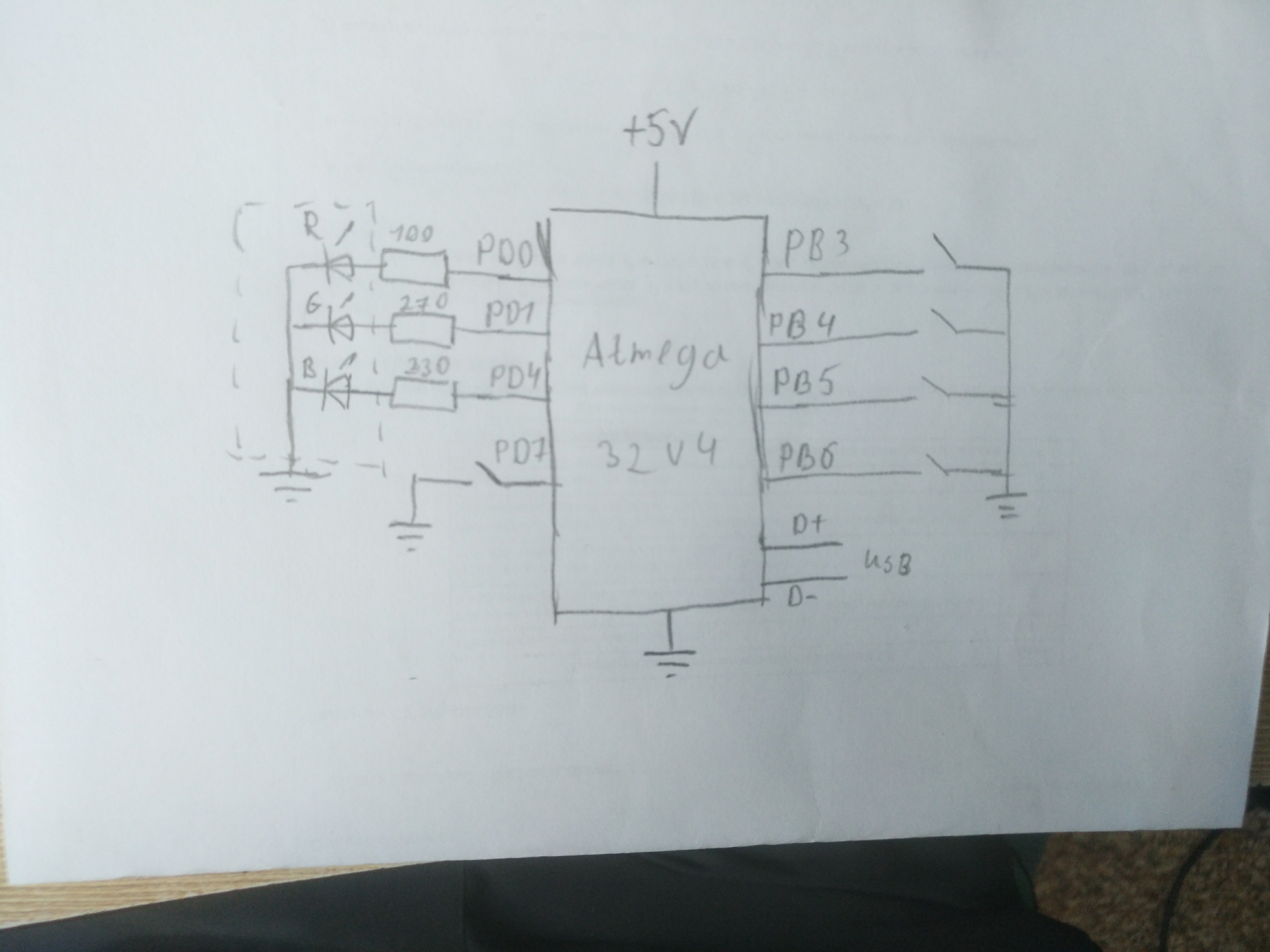
For pedals, I decided to immediately select 4 ports PB1-PB4, that is, two for the left and two for the right leg, although so far I have only 3 pedals. In addition, they are all in the same group and are located in one place. Under the LED, I took the outputs PD0, PD1 and PD4, under the button - PD7.
In this case, we do not need any pull-up resistors, if you use those that are built into the controller. However, then, when you press a button or pedal, the input will be low, and when released, it will be high, that is, the presses will be inverted, and you should not forget about this.
Code writing
This stage was the most difficult: due to a couple of errors in the pointers, I erased the bootloader several times and as a result I almost failed the board at the software level. Below all the stages of creating the firmware are described in detail, for those who just want to get a working code, it will be at the end of the article.
Training
First we need to understand what the pedal is in terms of the program. I decided to make it possible to set the pedals of one of two modes - real-time and trigger. In this case, each pedal has two programs: the first is performed when the pedal is held in real time or with odd taps in the trigger mode, the second - when the pedal is released in real time or when the taps are pressed evenly in trigger mode. The pedal also has a port, a state, and two variables - the current positions in programs 1 and 2. I got this structure:
struct pedal { char port; // char state; // , char oldState; // , char pos1; // 1 char pos2; // 2 unsigned char type; //0 — , 1 — ; unsigned char act1[16]; // 1 unsigned char act2[16]; // 2 };
Arduino has quite a bit of memory and is also 8-bit, so it's best to try to use char rather than int where possible.
We also need the standard Keyboard library to work as a keyboard.
Click Processing
Now we need to make an interpreter that will read data from the array and send it in the form of keystrokes to the machine, as well as select several values for various internal commands. We open the page with the key codes, and see what and how we can click. I did not dig deep and study all sorts of keyboard standards, as the information here seemed to me quite enough for such a project. The first half is reserved for standard ASCII characters (although some of them are not printable or not used), the second half is for various modifier keys. There are even separate codes for the left and right keys, which was very pleasing, but I did not see any special codes for the numbers from the nampad, although, as far as I know, they are perceived in a special way in the system than ordinary numbers. Perhaps their codes are somewhere in the “holes”, between the ranges, but now is not about that. So, the biggest code is the up key - 218, which means that the range 219-255 can be considered free, well, or at least there aren’t any important keys.
void pedalAction() { //255 , if (pedal1->type == 255) return; // unsigned char *prg; // char *pos; if (pedal1->type) { // int current; if ((current = digitalRead(ports[num])) != oldState[num]) { if (!current) state[num] = !state[num]; oldState[num] = current; } if (!state[num]) { //act1 pos2[num] = 0; pos = &(pos1[num]); prg = pedal1->act1; } else { //act2 pos1[num] = 0; pos = &(pos2[num]); prg = pedal1->act2; } } else { // if (!digitalRead(ports[num])) { //act1 pos2[num] = 0; pos = &(pos1[num]); prg = pedal1->act1; } else { //act2 pos1[num] = 0; pos = &(pos2[num]); prg = pedal1->act2; } } while (1) { if (prg[*pos] == 254) { // , *pos Keyboard.press(prg[++*pos]); } else if (prg[*pos] == 253) { // , *pos Keyboard.release(prg[++*pos]); } else if (prg[*pos] == 252) { //" ", ++*pos; return; } else if (prg[*pos] == 251) { // *pos+1 *pos = prg[*pos + 1]; return; } else if (prg[*pos] == 255 || prg[*pos] == 0) { // , return; } else { // Keyboard.write(prg[*pos]); } // , if (++*pos>=16) pos = 0; } }
I think that even a person with not the highest level of knowledge of C will not have questions about what is happening here. First, the function selects the desired pedal and determines, depending on the mode and condition of the pedal, which program should be performed. When reading each element of the array, if it is not a control character, the Keyboard.write () function is called, which emulates pressing and releasing a key. The control characters are processed separately and are needed to clamp the key combinations and navigate the program.
Some features of the keyboard mode
Keyboard.write () has some simple, but not obvious to beginners nuances, based on the fact that we send data not in raw form, but as keystrokes. Firstly, strangely enough, without additional drivers, the computer can only accept characters from the keyboard that are on the keyboard, which means that we will not be able to send any 0x03 (interrupt signal) or 0x1B (beginning of the ESCAPE sequence). Secondly, we can adjust the uppercase letters as they are in the ASCII table, but the machine will get the key combination Shift + <lowercase letter>. This can become a problem if we have CapsLock enabled, and we will "unexpectedly" receive small letters instead of large letters and vice versa. Thirdly, we cannot use the Russian language, as well as in any other language. This happens again due to such annoying things as key codes . Although Keyboard.write () accepts it as an argument, the code corresponding to the key on which it is in the standard English layout is still sent via USB, and if we try to send the Cyrillic alphabet, we will not know what. Therefore, if we want to say hello to our Russian-speaking friends through Arduino, then in the code we need to write “Ghbdtn”, and then send it, after selecting the Russian layout. Such a “greeting” will work in the Ukrainian layout, but in Bulgarian, despite the fact that there is also a Cyrillic alphabet, nothing will come of it, since the letters there are in completely different places. (I once heard the opinion that for many American and English developers it’s incomprehensible that someone might even need to use several layouts, but also switch them.)
So, we have an interpreter and a rough understanding of how our pedalboard interacts with a computer. Now we need to bring all this to the state of full firmware and check the performance on one pedal. If you create an instance of the pedal and cyclically call pedalAction (), then in theory we will execute the program specified in the structure.
struct pedal *pedal1 = {15, 0, 0, 0, 0, 0, "Hello, world!\0", 0}; void prepare () { pinMode(15, 2); //2 - INPUT_PULLUP, Keyboard.begin(); } void loop() { pedalAction(); }
By the way, never forget about null terminators in these “programs” if their length is less than the size of the array and if they are not cyclical, because Arduino will not only try to interpret the data that is not set, but will also send them to the machine with great speed, and this is the same as giving a monkey a keyboard.
One pedal is good, and two is better
Now it's time to deal with the processing of signals from several pedals, as well as add switching modes. At the beginning of the article, 4 ports were allocated for pedals, each of which must be allowed to work in seven modes. Why 7? Because without the use of PWM, our LED can give only 7 colors, and the eighth - off. This amount is quite enough for the average user, but in extreme cases it can easily be increased. This means that we will store the pedals in a two-dimensional array of 7 x 4. In order not to clog the memory, values common to several structures, such as the port number, can be taken out in separate arrays. As a result, we get something like this:
struct pedal { unsigned char type; unsigned char act1[16]; unsigned char act2[16]; }; struct pedal pedals[7][4] = { { { 255, {"Hello, world!\0"}, {255}}, {255, {255}, {255}}, {255, {255}, {255}}, {255, {255}, {255}} }, { { 255, {255}, {255}}, {255, {255}, {255}}, {255, {255}, {255}}, {255, {255}, {255}} }, { { 255, {255}, {255}}, {255, {255}, {255}}, {255, {255}, {255}}, {255, {255}, {255}} }, { { 255, {255}, {255}}, {255, {255}, {255}}, {255, {255}, {255}}, {255, {255}, {255}} }, { { 255, {255}, {255}}, {255, {255}, {255}}, {255, {255}, {255}}, {255, {255}, {255}} }, { { 255, {255}, {255}}, {255, {255}, {255}}, {255, {255}, {255}}, {255, {255}, {255}} }, { { 255, {255}, {255}}, {255, {255}, {255}}, {255, {255}, {255}}, {255, {255}, {255}} } }; char ports[4] = {15, 16, 14, 8}; char pos1[4] = {0, 0, 0, 0}; char pos2[4] = {0, 0, 0, 0}; char state[4] = {0, 0, 0, 0}; char oldState[4] = {0, 0, 0, 0}; char mode = 0; // char curPedal = 0; //
The magic of number 255
You probably noticed that in the article the number 255 often appears, where it would be more logical to put 0. Looking ahead, I will say that this is necessary for the convenience of storing pedals in EEPROM, since from the factory each of its cells contains not 0, but just 255, which means that this number will be much more convenient to use to indicate undefined variables than 0, so that you do not overwrite the memory each time.
It is important for us to know only the type of pedal and two programs, so we will leave them only directly in the structure, let the automation do the rest. The prepare and loop methods will now look like this:
void prepare(){ pinMode(2, 1); pinMode(3, 1); pinMode(4, 1); pinMode(6, 2); for (int i : ports) pinMode(i, 2); Keyboard.begin(); } void loop() { for (int i = 0; i < 6; i++) { int current; if ((current = digitalRead(modeButton)) != last) { if (!current) { if (++mode >= 7) mode = 0; while (pedals[mode][0].type == 255 && pedals[mode][1].type == 255 && pedals[mode][2].type == 255 && pedals[mode][3].type == 255) if (++mode >= 7) { mode = 0; break; } } last = current; digitalWrite(2, (mode + 1) & 0b001); digitalWrite(3, (mode + 1) & 0b010); digitalWrite(4, (mode + 1) & 0b100); for (int i = 0; i < 4; i++) { pos1[i] = 0; pos2[i] = 0; state[i] = 0; oldState[i] = 0; } delay(50); } curPedal = i; pedalAction } } }
The controller will consider the mode unused if not a single pedal is declared in it (mode = 255), which means that when it hits it, it will immediately go to the next, but the first mode will always exist. When switching the mode, all values in the arrays are nullified, since we do not need to save them for each mode (right?), And then the loop bypasses all the pedals and calls pedalAction for them.
Also, at the beginning of the pedalAction () method, you need to add the following line so that it understands which of the structures to deal with:
struct pedal *pedal1 = &pedals[mode][curPedal];
The existing pedal1 structure can be removed as unnecessary.
All this also works quite well, however, I encountered one problem: some programs do not have time to receive clicks at the speed with which Arduino sends them. The most obvious solution is to add the ability to set delays between actions where necessary. It’s only when we sit down to write programs for microcontrollers that all the chips, like hardware multithreading, remained somewhere there, in high-level computers, when we add a delay, the whole program stops until the controller counts the right number of cycles. Since we do not have multithreading, we will have to create it.
Hard to say yes easy to do
I did not begin to reinvent the wheel, but took the finished library ArduinoThread. Here you can read a little about how it works and download it. You can download the library from the Arduino IDE itself. In short, it allows you to periodically perform a function with a certain interval, while not allowing you to go into an infinite loop if the execution takes longer than the interval. Exactly what is needed. Create another array with threads for each pedal:
Thread pedalThreads[6] = {Thread(pedalAction, 10), Thread(pedalAction, 10), Thread(pedalAction, 10), Thread(pedalAction, 10), Thread(pedalAction, 10), Thread(pedalAction, 10)};
Now we have 6 identical virtual threads, but at the same time they are different objects.
Let's rewrite the pedal cycle for working with the new functionality:
... for (int i = 0; i < 4; i++) { if (pedalThreads[i].shouldRun()) { curPedal = i; pedalThreads[i].run(); } } ...
Now the value of 252 in the program array, which corresponds to “doing nothing,” will give a delay of 10 milliseconds (although actually a little more, since the execution of the code also takes time). Adding a few lines to the interpreter will make it possible to set the delay in several of these "quanta", spending only 2 bytes of the array:
... if (wait[num]) { wait[num]--; return; } else if (prg[*pos] == 250) { wait[num] = prg[++*pos]; } ...
Unlike other commands, this instruction must be added precisely at the beginning of the interpreter, that is, immediately after “while (1) {”, since the delay must be processed before the interpreter proceeds to read the program. The wait array needs to be declared in the same way as it was done with ports, state, etc. and also reset its cells when switching the mode, so that the delay does not go to another program.
Now, with the possibility of setting the delay to 2.55 seconds, problems with the definition of keys by programs should not arise.
On-the-go programming
In principle, here it would be possible to finish the code and start assembling the device, but in this case, if someone suddenly wants to reprogram the pedals, he will have to open the Arduino IDE, edit the code, and reload the firmware. Naturally, this option is not the best, so I decided to add the ability to change the program from the Arduino serial port, and store the programs themselves in EEPROM. To work with non-volatile memory, you must connect the standard library EEPROM.h. The programming mode code is as follows:
... if (!digitalRead(modeButton)) { // Serial.begin(9600); while (!Serial) { PORTD = 0b00000000 + (PORTD & 0b11101100); delay(250); PORTD = 0b00010000 + (PORTD & 0b11101100); delay(250); } Serial.println(F("***Programming mode***")); Serial.println(F("Write the command as <m> <p> <c>")); Serial.println(F("m - number of mode, one digit")); Serial.println(F("p - number of pedal, one digit")); Serial.println(F("c - command, it can be:")); Serial.println(F("\tr - read pedal info")); Serial.println(F("\tw - enter to writing mode and change pedal programm")); Serial.println(F("\te - erase pedal programm and delete it")); Serial.println(F("There are up to 7 modes and 6 pedals per mode can be configured")); Serial.println(F("Mode will be incative if there is no pedal configured in it")); while (1) { while (Serial.available()) { Serial.read(); delay(1); } PORTD = 0b00000001 + (PORTD & 0b11101100); Serial.println(""); Serial.println(F("Enter command")); while (!Serial.available()); PORTD = 0b00000010 + (PORTD & 0b11101100); delay(3); if (Serial.available() == 3) { int curMode = Serial.read() - 48; int curPedal = Serial.read() - 48; char cmd = Serial.read(); if (curMode > 6 || curMode < 0) { Serial.print(F("Mode must be in 0-6. You entered ")); Serial.println(curMode); continue; } if (curPedal > 3 || curPedal < 0) { Serial.print(F("Pedal must be in 0-3. You entered ")); Serial.println(curPedal); continue; } Serial.println(); if (cmd == 'r') { int beginAddress = sizeof(struct pedal) * (curMode * 6 + curPedal); Serial.print("type: "); int curAddress = beginAddress; Serial.println(EEPROM[curAddress++]); Serial.print("act1: "); for (int i = curAddress ; i < curAddress + (sizeof(struct pedal) - 1) / 2; i++) { Serial.print(EEPROM[i]); Serial.print("\t"); } Serial.println(); curAddress = beginAddress + 1 + (sizeof(struct pedal) - 1) / 2; Serial.print("act2: "); for (int i = curAddress ; i < curAddress + (sizeof(struct pedal) - 1) / 2; i++) { Serial.print(EEPROM[i]); Serial.print("\t"); } Serial.println(); } else if (cmd == 'w') { Serial.println(F("Enter type:")); PORTD = 0b00000001 + (PORTD & 0b11101100); while (!Serial.available()); int beginAddress = sizeof(struct pedal) * (curMode * 6 + curPedal); int curAddress = beginAddress; PORTD = 0b00000010 + (PORTD & 0b11101100); EEPROM[curAddress++] = (char)Serial.parseInt(); PORTD = 0b00000001 + (PORTD & 0b11101100); Serial.println(F("Enter act1 in DEC divided by space:")); while (Serial.available()) { Serial.read(); delay(1); } while (!Serial.available()); PORTD = 0b00000010 + (PORTD & 0b11101100); while (Serial.available()) { EEPROM[curAddress++] = (char)Serial.parseInt(); delay(1); } PORTD = 0b00000001 + (PORTD & 0b11101100); curAddress = beginAddress + 1 + (sizeof(struct pedal) - 1) / 2; Serial.println(F("Enter act2 in DEC divided by space:")); while (Serial.available()) { Serial.read(); delay(1); } while (!Serial.available()); PORTD = 0b00000010 + (PORTD & 0b11101100); while (Serial.available()) { EEPROM[curAddress++] = (char)Serial.parseInt(); delay(1); } PORTD = 0b00000001 + (PORTD & 0b11101100); Serial.println(F("Finished, don't forget to verify written data!")); } else if (cmd == 'e') { int beginAddress = sizeof(struct pedal) * (curMode * 6 + curPedal); Serial.println(F("Disabling pedal...")); PORTD = 0b00000010 + (PORTD & 0b11101100); EEPROM[beginAddress] = 255; PORTD = 0b00000001 + (PORTD & 0b11101100); Serial.println(F("Pedal disabled")); } } else { Serial.println(F("Incorrect command, please read help above")); } }; } ...
What this code does is explained by the help contained in it: a space number is entered for the mode number, pedal number, and a command, of which there are 3 — reading, writing, and
Features of work with EEPROM
I would also like to draw attention to the lines of the form:
Thanks to this library, from the programmer’s point of view, non-volatile memory is an ordinary char array, but, as “arduino”, we need to understand that writing to ROM is a very difficult operation, which takes as much as ~ 3 seconds from the controller, and it’s advisable not to interrupt this process. This design makes the diode shine red during such operations, and then returns the “safe” green color back.
PORTD = 0b00000010 + (PORTD & 0b11101100); ... PORTD = 0b00000001 + (PORTD & 0b11101100);
Thanks to this library, from the programmer’s point of view, non-volatile memory is an ordinary char array, but, as “arduino”, we need to understand that writing to ROM is a very difficult operation, which takes as much as ~ 3 seconds from the controller, and it’s advisable not to interrupt this process. This design makes the diode shine red during such operations, and then returns the “safe” green color back.
In the program recording mode, the input is made directly by the values of bytes in the decimal number system with a space. It turns out pretty harsh, but you don’t have to write a complex parser. Moreover, reprogramming does not occur so often, and in these cases it is quite possible to look into the ASCII table.
With the preservation of the structures sorted out, now we need to somehow pull out our data from there and convert it to the "pedal" view:
... for (int i = 0; i < 7; i++) { for (int j = 0; j < 4; j++) { struct pedal *p = &pedals[i][j]; int beginAddress = sizeof(struct pedal) * (i * 6 + j); int curAddress = beginAddress; unsigned char type = EEPROM[curAddress++]; if (type == 0 || type == 1) { p->type = type; for (int k = 0 ; k < 16; k++) { p->act1[k] = EEPROM[curAddress++]; } for (int k = 0 ; k < 16; k++) { p->act2[k] = EEPROM[curAddress++]; } } } } ...
Nothing supernatural happens here either: the controller reads the data from the memory and fills the existing structures with it.
The advantage of programming through UART is that we again do not need any special drivers, so you can set the behavior of the manipulator even from the phone.
Demonstration
Full source code
He is here
#include <Keyboard.h> #include <Thread.h> #include <EEPROM.h> #define modeButton 6 struct pedal { unsigned char type; //0 — , 1 — , 255 — unsigned char act1[16]; unsigned char act2[16]; }; struct pedal pedals[7][4] = { { { 255, {255}, {255}}, {255, {255}, {255}}, {255, {255}, {255}}, {255, {255}, {255}} }, { { 255, {255}, {255}}, {255, {255}, {255}}, {255, {255}, {255}}, {255, {255}, {255}} }, { { 255, {255}, {255}}, {255, {255}, {255}}, {255, {255}, {255}}, {255, {255}, {255}} }, { { 255, {255}, {255}}, {255, {255}, {255}}, {255, {255}, {255}}, {255, {255}, {255}} }, { { 255, {255}, {255}}, {255, {255}, {255}}, {255, {255}, {255}}, {255, {255}, {255}} }, { { 255, {255}, {255}}, {255, {255}, {255}}, {255, {255}, {255}}, {255, {255}, {255}} }, { { 255, {255}, {255}}, {255, {255}, {255}}, {255, {255}, {255}}, {255, {255}, {255}} } }; char ports[4] = {8, 16, 15, 14}; char pos1[4] = {0, 0, 0, 0}; char pos2[4] = {0, 0, 0, 0}; char state[4] = {0, 0, 0, 0}; char oldState[4] = {0, 0, 0, 0}; char wait[4] = {0, 0, 0, 0}; void pedalAction(); char mode = 0; char curPedal; Thread pedalThreads[6] = {Thread(pedalAction, 10), Thread(pedalAction, 10), Thread(pedalAction, 10), Thread(pedalAction, 10), Thread(pedalAction, 10), Thread(pedalAction, 10)}; void setup() { pinMode(2, 1); pinMode(3, 1); pinMode(4, 1); pinMode(modeButton, 2); if (!digitalRead(modeButton)) { // Serial.begin(9600); while (!Serial) { PORTD = 0b00000000 + (PORTD & 0b11101100); delay(250); PORTD = 0b00010000 + (PORTD & 0b11101100); delay(250); } Serial.println(F("***Programming mode***")); Serial.println(F("Write the command as <m> <p> <c>")); Serial.println(F("m - number of mode, one digit")); Serial.println(F("p - number of pedal, one digit")); Serial.println(F("c - command, it can be:")); Serial.println(F("\tr - read pedal info")); Serial.println(F("\tw - enter to writing mode and change pedal programm")); Serial.println(F("\te - erase pedal programm and delete it")); Serial.println(F("There are up to 7 modes and 6 pedals per mode can be configured")); Serial.println(F("Mode will be incative if there is no pedal configured in it")); while (1) { while (Serial.available()) { Serial.read(); delay(1); } PORTD = 0b00000001 + (PORTD & 0b11101100); Serial.println(""); Serial.println(F("Enter command")); while (!Serial.available()); PORTD = 0b00000010 + (PORTD & 0b11101100); delay(3); if (Serial.available() == 3) { int curMode = Serial.read() - 48; int curPedal = Serial.read() - 48; char cmd = Serial.read(); if (curMode > 6 || curMode < 0) { Serial.print(F("Mode must be in 0-6. You entered ")); Serial.println(curMode); continue; } if (curPedal > 3 || curPedal < 0) { Serial.print(F("Pedal must be in 0-3. You entered ")); Serial.println(curPedal); continue; } Serial.println(); if (cmd == 'r') { int beginAddress = sizeof(struct pedal) * (curMode * 6 + curPedal); Serial.print("type: "); int curAddress = beginAddress; Serial.println(EEPROM[curAddress++]); Serial.print("act1: "); for (int i = curAddress ; i < curAddress + (sizeof(struct pedal) - 1) / 2; i++) { Serial.print(EEPROM[i]); Serial.print("\t"); } Serial.println(); curAddress = beginAddress + 1 + (sizeof(struct pedal) - 1) / 2; Serial.print("act2: "); for (int i = curAddress ; i < curAddress + (sizeof(struct pedal) - 1) / 2; i++) { Serial.print(EEPROM[i]); Serial.print("\t"); } Serial.println(); } else if (cmd == 'w') { Serial.println(F("Enter type:")); PORTD = 0b00000001 + (PORTD & 0b11101100); while (!Serial.available()); int beginAddress = sizeof(struct pedal) * (curMode * 6 + curPedal); int curAddress = beginAddress; PORTD = 0b00000010 + (PORTD & 0b11101100); EEPROM[curAddress++] = (char)Serial.parseInt(); PORTD = 0b00000001 + (PORTD & 0b11101100); Serial.println(F("Enter act1 in DEC divided by space:")); while (Serial.available()) { Serial.read(); delay(1); } while (!Serial.available()); PORTD = 0b00000010 + (PORTD & 0b11101100); while (Serial.available()) { EEPROM[curAddress++] = (char)Serial.parseInt(); delay(1); } PORTD = 0b00000001 + (PORTD & 0b11101100); curAddress = beginAddress + 1 + (sizeof(struct pedal) - 1) / 2; Serial.println(F("Enter act2 in DEC divided by space:")); while (Serial.available()) { Serial.read(); delay(1); } while (!Serial.available()); PORTD = 0b00000010 + (PORTD & 0b11101100); while (Serial.available()) { EEPROM[curAddress++] = (char)Serial.parseInt(); delay(1); } PORTD = 0b00000001 + (PORTD & 0b11101100); Serial.println(F("Finished, don't forget to verify written data!")); } else if (cmd == 'e') { int beginAddress = sizeof(struct pedal) * (curMode * 6 + curPedal); Serial.println(F("Disabling pedal...")); PORTD = 0b00000010 + (PORTD & 0b11101100); EEPROM[beginAddress] = 255; PORTD = 0b00000001 + (PORTD & 0b11101100); Serial.println(F("Pedal disabled")); } } else { Serial.println(F("Incorrect command, please read help above")); } }; } for (int i : ports) pinMode(i, 2); pinMode(17, 1); for (int i = 0; i < 7; i++) { for (int j = 0; j < 4; j++) { struct pedal *p = &pedals[i][j]; int beginAddress = sizeof(struct pedal) * (i * 6 + j); int curAddress = beginAddress; unsigned char type = EEPROM[curAddress++]; if (type == 0 || type == 1) { p->type = type; for (int k = 0 ; k < 16; k++) { p->act1[k] = EEPROM[curAddress++]; } for (int k = 0 ; k < 16; k++) { p->act2[k] = EEPROM[curAddress++]; } } } } Keyboard.begin(); } int last = 0; void loop() { int current; if ((current = digitalRead(modeButton)) != last) { if (!current) { if (++mode >= 7) mode = 0; while (pedals[mode][0].type == 255 && pedals[mode][1].type == 255 && pedals[mode][2].type == 255 && pedals[mode][3].type == 255) if (++mode >= 7) { mode = 0; break; } } last = current; digitalWrite(2, (mode + 1) & 0b001); digitalWrite(3, (mode + 1) & 0b010); digitalWrite(4, (mode + 1) & 0b100); for (int i = 0; i < 4; i++) { pos1[i] = 0; pos2[i] = 0; state[i] = 0; oldState[i] = 0; wait[i] = 0; } delay(50); } for (int i = 0; i < 4; i++) { if (pedalThreads[i].shouldRun()) { curPedal = i; pedalThreads[i].run(); } } } void pedalAction() { struct pedal *pedal1 = &pedals[mode][curPedal]; if (pedal1->type == 255) return; unsigned char *prg; char *pos; if (pedal1->type) { int current; if ((current = digitalRead(ports[curPedal])) != oldState[curPedal]) { if (!current) state[curPedal] = !state[curPedal]; oldState[curPedal] = current; } if (!state[curPedal]) { //act1 pos2[curPedal] = 0; pos = &(pos1[curPedal]); prg = pedal1->act1; } else { //act2 pos1[curPedal] = 0; pos = &(pos2[curPedal]); prg = pedal1->act2; } } else { if (!digitalRead(ports[curPedal])) { //act1 pos2[curPedal] = 0; pos = &(pos1[curPedal]); prg = pedal1->act1; } else { //act2 pos1[curPedal] = 0; pos = &(pos2[curPedal]); prg = pedal1->act2; } } while (1) { if (wait[curPedal]) { wait[curPedal]--; return; } else if (prg[*pos] == 250) { wait[curPedal] = prg[++*pos]; } else if (prg[*pos] == 254) { // , *pos Keyboard.press(prg[++*pos]); } else if (prg[*pos] == 253) { // , *pos Keyboard.release(prg[++*pos]); } else if (prg[*pos] == 252) { delay(10); //" ", ++*pos; return; } else if (prg[*pos] == 251) { // *pos+1 *pos = prg[*pos + 1]; return; } else if (prg[*pos] == 255 || prg[*pos] == 0) { // , return; } else { // Keyboard.write(prg[*pos]); } // , if (++*pos >= 16) pos = 0; } }
Afterword
Although initially I did a pedalboard for the possibility of scrolling the recording while playing the guitar, however, personally I found it convenient to use the pedals in ordinary tasks, the main thing is to get a little used to such an unusual manipulator. And here there is one more problem: without favorite pedals, working on the contrary becomes more difficult, since you have to remember what, where and why to press. If pedals can still be worn and connected to the office, then at the institute it is more difficult to run around with them in classrooms. So to use this device for something other than its original purpose is at your own peril and risk.
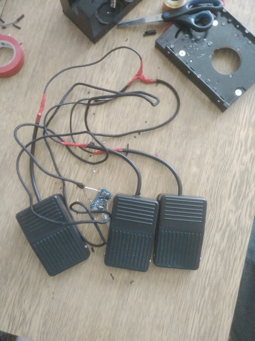
Assembled pedalboard:
All Articles