Making a controller for a smart home
We make a controller for a smart home and not only.
In a previous article, I described the development of the system as a whole. In this, I will describe the development of a controller that is responsible for polling sensors and I / O modules. “Why reinvent the wheel?” You ask. Firstly, it is interesting, and secondly, strangely enough, there is no OpenSource solution for such a controller covering both software and hardware. The article is aimed at people who are a little versed in electronics and in embedded linux development.
Making a controller, you say, is so complicated - you need to make a board, write software, print the case. But in reality, everything is a little bit more complicated, that's what it poured for me, but you are right in principle:
1. controller hardware
- choice of cpu board for the controller
- choice of IO controller
- choice of power supply
- block diagram of the controller
- development of a cross board for the controller
- development of boards for RS-485 modules
- production of boards
2. software for the controller
- choice of build system for linux kernel and rootfs
- partition structure of the SD card
- selecting a bootloader and loading the desired rootfs
- changes in device tree
- the choice of a system for collecting traded debits
- writing a build system
- writing a communication core
- writing mqtt gateway (discrete / analog controller points -> mqtt topics)
- writing a Google parser and building a json configuration file for the gateway
- writing a point monitor to access controller points
- mount readonly file system
3. controller case
- what it should be, connectors, cooling, seats for a board, mortgages for clips for brackets for dinrake.
- design and printing
A few words about the hardware.
Probably only the most desperate now take a separate processor, memory, flash, power controller, a couple more hundred components and begin to sculpt it all together. The rest use the fruits of other people's labors, it’s faster and easier. You just need to open a browser and write “single board computer” and spend the rest of the day choosing the right one. I needed a lot of serial ports and it is desirable that the board supports -40 ° C to + 85 ° C, so the choice fell on BeagleBone Black (BBB). Also on BBB, all peripherals are connected to two PBD connectors of 46 pins with a pitch of 2.54, which is convenient for prototyping and developing a cross-board. A cross board is needed to combine all the components on one board, for me it is a cpu board, power supply, IO controller, and RS485 channel boards. Also, it is the cross-board that needs to be fixed to the case and there are connectors on it for power and RS485 cable.

So, we figured out the cpu board, the next thing to decide is whether it is necessary to put an Input / Output (IO) controller on the cross-board or not. I laid it on the board, and I have not successfully used it yet. The only thing he does is postpone the start of the BBB for 1s after applying power and serves the reset button.
The power supply for the controller I took the ready-made MeanWell NSD10-12S5, developing it for a single device is a meaningless undertaking, I just picked it up for consumption and that's it. Do not pay attention to the LCD, it is on the board, but I did not implement support.

A few words about RS485 channel cards.
There are 4 serial BBB interfaces on the cross board. So there you can put any type of channel you need, RS485, CAN, Zigbee module ...
I needed RS485 channels, so I made only them, they are with automatic reception / transmission control and with galvanic isolation. Why not use transceiver control with BBB, because TI officially stopped supporting the strobe for RS485 in the serial device driver. You can find a patch for the driver, you can add it yourself, but why? Having made the channel self-locking, you can put it on any board, for example, on RaspberyPi, where there has never been such support, if there was, then correct me. The strobe for the rs485 driver is configured on attiny10, cheap and cheerful.
Go back to the software.
Choosing a build system for the linux kernel and rootfs.
There are several systems of this kind, the most popular are Yocto and BuildRoot. If you need to develop a large project, if you have a lot of time and desire to write recipes, then Yocto is your choice. With the help of BuildRoot, you can collect everything you need to easily start the board very, very simple, because I am making a system on Beaglebone Black (hereinafter BBB) then:
That's all. Now everything you need to run the board lies in the / buildroot / output / images folder.
Everything looks very simple and not interesting, so you can do a little more complicated:
As a result, buildroot will generate zImage and rootfs.tar
Selecting the partition structure of the SD card:
On this, I think, it is not necessary to focus much attention.
I made 4 sections BOOT / ROOT_1 / ROOT_2 / DATA.
The BOOT section stores everything you need for bootstrapping: MLO, barebox.bin, barebox.env, am335x-boneblack.dtb, zImage, boot.txt.
ROOT_1 and ROOT_2 contain rootfs, the selection of which is written in the boot.txt file (see below). All of these partitions are mounted as readonly to avoid file system crashes when the power is turned off. DATA contains design configs, when changing which there is no need to rebuild the code.
Such a structure of partitions in the future will make it easy to write a software update component. This component will overwrite one of the sections ROOT_1 / ROOT_2, which is not used now, and then just change the boot.txt file if you do not need to change the kernel.
Choosing a bootloader.
I had a lot of experiments with bootloaders for BBB. At first I used, like everyone else, the U-Boot that BuildRoot generates. But I did not like it, maybe, of course, this is a matter of habit, but it seemed to me that this was too much, it is very difficult and difficult to configure. Then, I thought that it would not be bad to start the system quickly, in 2-3 seconds, and file the X-Loader so that it would load the kernel, I succeeded, but again there was a configuration issue, and the start time for me not critical (the system on systemd boots slowly by itself, even if you delete everything that is not needed).
In the end, I settled on barebox, I really liked its simplicity, plus the site has all the documentation (www.barebox.org).
For example, to load rootfs from the first or second partition, you just need to:
1. on the boot section, make the file boot.txt which will export a variable of the type “export BOOT_NUM = X”
2. make two scripts / env / boot / sdb1 / env / boot / sdb2 in which to describe the boot parameters, for example:
3. make a script / env / boot / sd in which depending on BOOT_NUM start sdb1 or sdb2 script
4. set the variable boot.default
5. Further changing BOOT_NUM in boot.txt we will load rootfs from the first or second partition, which in the future can be used for software update.
Changes to device tree.
Since I use MODBUS RTU via RS485 to communicate with the modules, I needed to enable almost all the serial ports that exist on the BBB. To do this, you need to reenable them in the device tree, because By default, most of them are turned off.
It would be correct to make your patch for the am335x-bone-common.dtsi file from the buildrut package and apply it every time before assembling it, but laziness won, and I just pulled out all the files I needed, changed everything I needed and built it up with my hands.
Because this is done once, it is possible and so:
1. Create a folder with files necessary for assembly:
2. In the am335x-bone-common.dtsi file, you need to correctly configure the pins and un-enable the port drivers:
3. Next, a little magic, and the finished file am335x-boneblack.dtb lies in the same directory:
b. run the preprocessor:
c. run the compiler itself:
4. am335x-boneblack.dtb should be put on the boot partition next to the kernel and in the startup script for barebox add the following line - "
"
Choosing a system for collecting traded debits.
As you know, systems without bugs do not exist, as well as the analysis of a multithreaded system without traces. It is very convenient if these traces are not displayed simply in the console, but are collected using something specially created for this, so that it would be possible to sort them by processes, apply filters, etc. And I just know one good system that is easy to build under both host and target. This is DLT, if you have never heard of this, then it does not matter, all knowledge gaps can be easily covered by reading at.projects.genivi.org/wiki/display/PROJ/Diagnostic+Log+and+Trace .
This system consists of dlt-daemon and dlt-viewer. As the name implies, dlt-daemon runs on the target, and dlt-viewer on the host. Plus to all this, to your binary, from which we want to collect traces, you need to link the dlt lib.
In general, everything is convenient, how to collect traces and analyze them, I recommend.
Writing a build system.
Why write a build system, because you can download everything from the repositories, build it with your hands, build on the basis of this rootfs and veil, the controller works. But to repeat such a trick in a month will be more difficult, and in two - this is generally impossible. Again, you have to remember what, where to put, what to build and how to start. Therefore, having spent a lot of time at first, you save it later, plus you get the opportunity to conveniently build under host and target. The build system consists of a set of scripts that first prepare the host for the build, download third-party components, such as buildroot, mosquitto, DLT daemon, from their repositories, build them, put them in their places. And then you can launch the build of your project. If the build under the host is not difficult to do, then you always need to tinker with the build under the target, and it would be better if the script does it.
Buildroot can be configured so that it invokes a post-build script after it forms rootfs, which will lie in buildroot / output / target. This gives you a great opportunity to put everything you need there. And then, the file system image will already contain everything you need to start your system.
The recipe is something like this:
After that, you just need to unpack buildroot / output / images / rootfs.tar to the desired section of the SD card and turn on the power.
Writing a communication core.
The concept of this is as old as modbus itself.
Each I / O device in a modbus network has registers (16 bit) available for reading, reading / writing, in which data is stored and through which these devices are controlled. The controller, in turn, has arrays of discrete (status and byte value) and analog points (status and float value), in which it stores the state of all parameters.
So, the task of the communication core is simple - to collect data from I / O devices using the modbus protocol, map them to controller points and provide access to these points for the upper level. And if you need to manage something, then everything is in the other direction - the logical device (more on that later) must be subscribed to the controller point and writing to this point initiates the translation of this parameter to the physical water-output device.
In order to somehow structure the data and work with devices, you can introduce the concept of a logical device that will display the state of a physical device in your software.
I also decided to divide the logical devices into two groups:
From all of the above, it’s logical to have some kind of configurator for the controller, whether it’s just a json config or a self-written tool generating a binary config, anything suits. I have the second option, because there were ideas to write a communication core so that it could be easily run not only on the Linux board but also on Arduin with FreeRtos, changing the PAL level in the software.
In the configurator for each device, you need to set the controller port number rs485, the device address, and the controller point to which the status of communication with the device is displayed, plus for each standard device its channels are described, and for the user device, its registers are mapped to points.

Such a configuration file, containing all the necessary data on the construction of the modbus network, allows you to not modify the source code for the project if you need to add / remove / change I / O devices, just change the parameters in the configurator and save them in the config file.
At startup, the communication core parses the config and creates on its basis lists of logical devices for each rs485 port of the controller, then threads are created on each port and a cyclic polling of physical devices begins.
Writing mqtt gateway.
Actually - your controller points, both discrete and analog, with a proprietary interface for access to them, are of little interest to anyone. So there is only one way out - mqtt. I think I will not exaggerate if I say that this is currently the most common protocol for exchanging small messages, plus it is very simple and understandable to use. So when I needed to broadcast data from the controller - I did not think long about what to use.
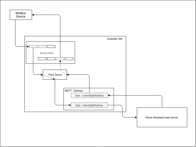
Because I have a lot of parameters, then there were constantly confusions in the gateway configuration file, where the mapping of controller points to mqtt gateway topics was registered. Google helped the table, and writing the csv parser of this table in the json configuration file for the gateway.

gateway git repo
parser git repo
Writing point monitor.
Sometimes it’s very useful to see what is happening with the controller points, for this I wrote a small application that connects directly to the communication core and reads the status of discrete and analog points. I’m pretty tight with the UI, so I was able to somehow throw the application into QML, it worked with a squeak, you can count the point, you can record it, but I don’t need more.
Mount readonly file system.
Usually, few people pay attention to this, and even in production projects, you can find devices in which the partition with rootfs is writable. This sooner or later leads to the crash of any, even the most stable file system. Because Since the controller can be turned off at any time, it is only a matter of time / case when this happens. To minimize this probability, you need to tinker a bit with fstab and put the rootfs image there before putting the image, as described above. In fstab, firstly, you need to mount the file system as readonly, and secondly, everything that can change can be mapped into tmpfs.
My fstab is this, it may differ for you:
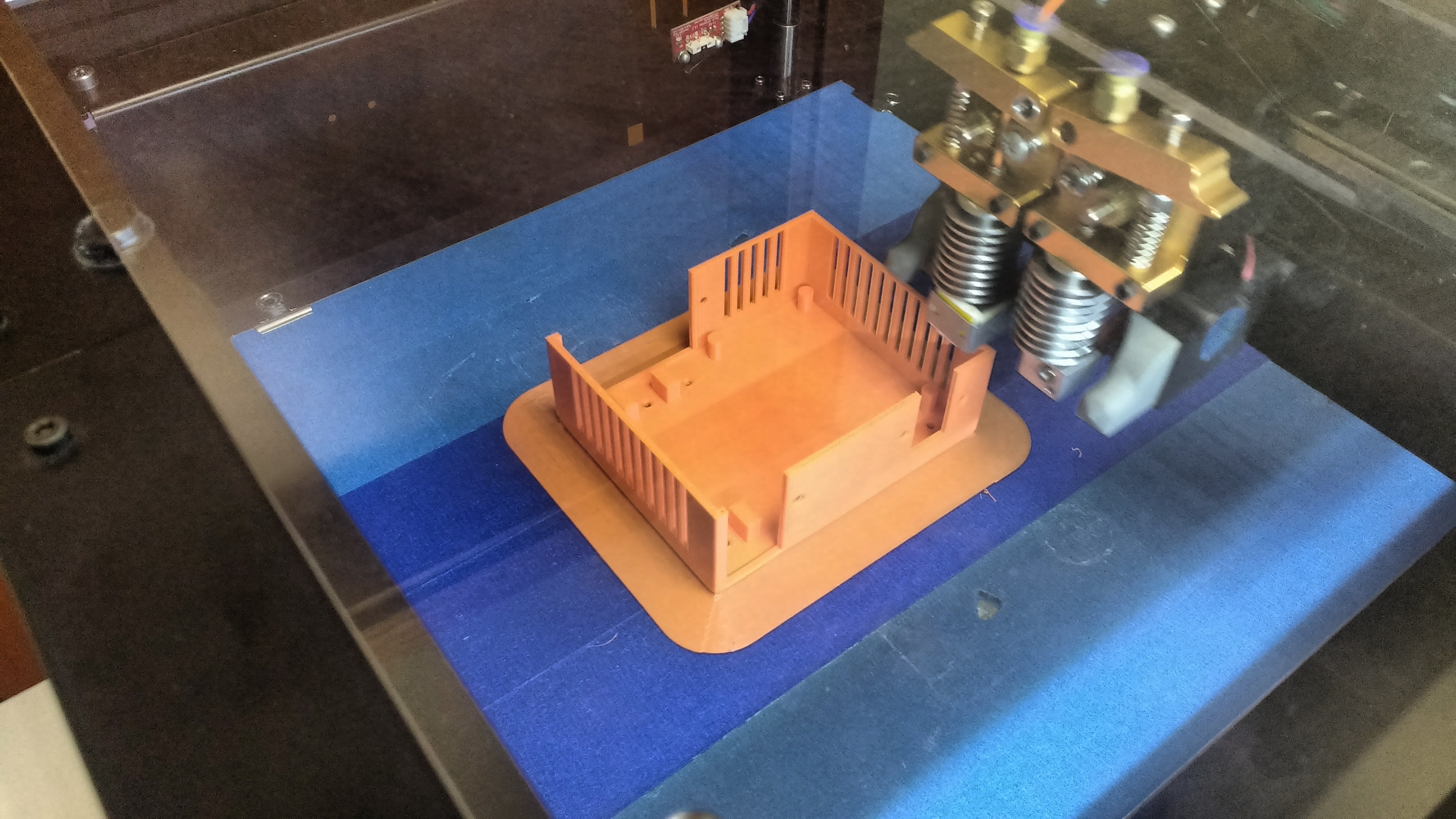
Controller body
The 3D printer has long been included in the masthead sections for each collective farmer engineer, unfortunately I do not have it, but it is at work. Recently, the excitement of other employees for him has disappeared, I use this when printing everything I need and do not need, you could be convinced of this by reading my previous post.
We draw in FreeCAD, we generate the gcode in Cura and we get a case, without forgetting to make seats for the board, cutouts for connectors and cooling and mortgages for clips on a din rail.

Well, that’s all, now we have a board, software on an SD card and a case. We take a file (I’m not joking) and connect everything together, connect the power, RS485 cables and everything starts to work. And you said difficult, difficult ...
In a previous article, I described the development of the system as a whole. In this, I will describe the development of a controller that is responsible for polling sensors and I / O modules. “Why reinvent the wheel?” You ask. Firstly, it is interesting, and secondly, strangely enough, there is no OpenSource solution for such a controller covering both software and hardware. The article is aimed at people who are a little versed in electronics and in embedded linux development.
Making a controller, you say, is so complicated - you need to make a board, write software, print the case. But in reality, everything is a little bit more complicated, that's what it poured for me, but you are right in principle:
1. controller hardware
- choice of cpu board for the controller
- choice of IO controller
- choice of power supply
- block diagram of the controller
- development of a cross board for the controller
- development of boards for RS-485 modules
- production of boards
2. software for the controller
- choice of build system for linux kernel and rootfs
- partition structure of the SD card
- selecting a bootloader and loading the desired rootfs
- changes in device tree
- the choice of a system for collecting traded debits
- writing a build system
- writing a communication core
- writing mqtt gateway (discrete / analog controller points -> mqtt topics)
- writing a Google parser and building a json configuration file for the gateway
- writing a point monitor to access controller points
- mount readonly file system
3. controller case
- what it should be, connectors, cooling, seats for a board, mortgages for clips for brackets for dinrake.
- design and printing
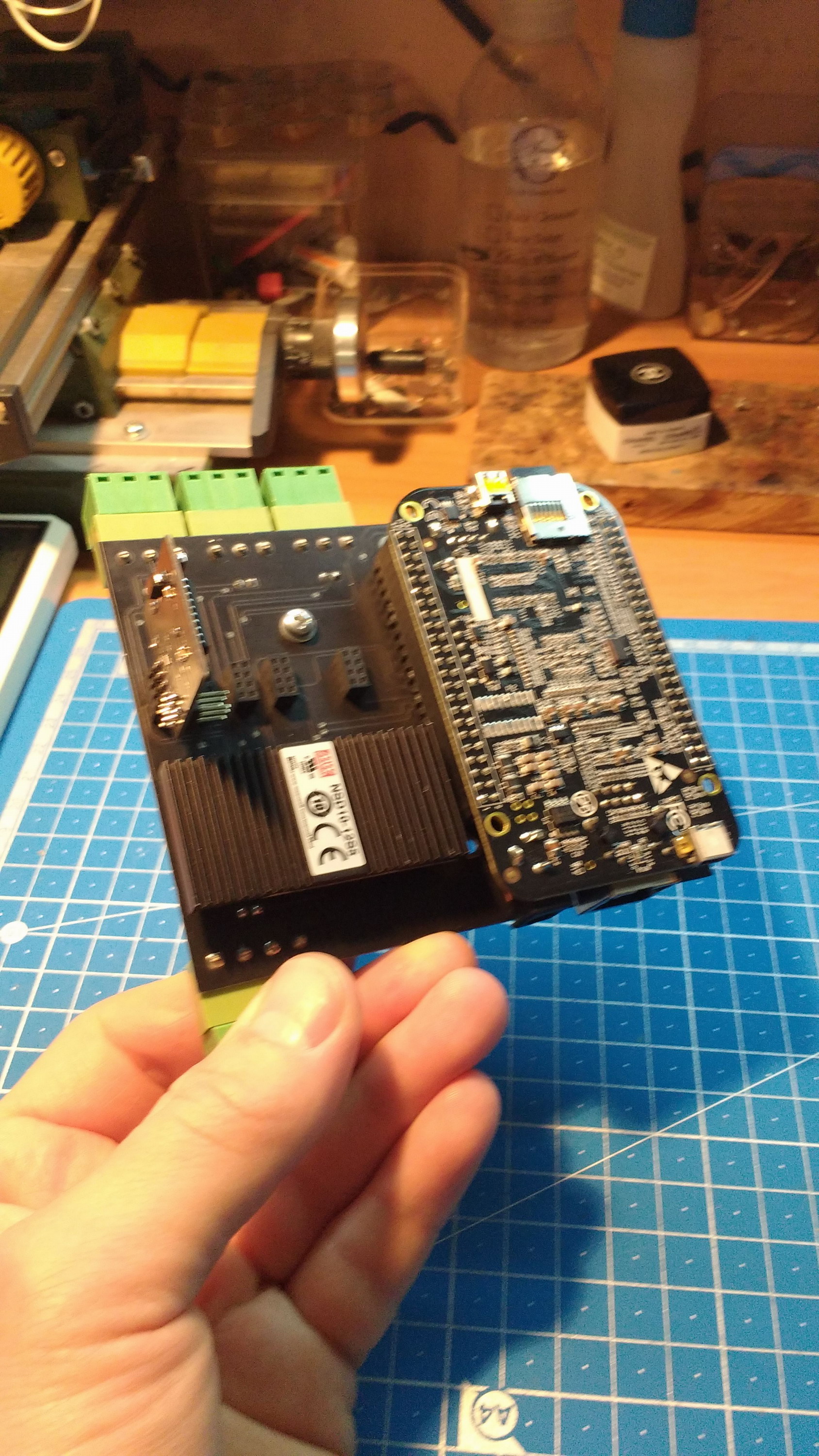
A few words about the hardware.
Probably only the most desperate now take a separate processor, memory, flash, power controller, a couple more hundred components and begin to sculpt it all together. The rest use the fruits of other people's labors, it’s faster and easier. You just need to open a browser and write “single board computer” and spend the rest of the day choosing the right one. I needed a lot of serial ports and it is desirable that the board supports -40 ° C to + 85 ° C, so the choice fell on BeagleBone Black (BBB). Also on BBB, all peripherals are connected to two PBD connectors of 46 pins with a pitch of 2.54, which is convenient for prototyping and developing a cross-board. A cross board is needed to combine all the components on one board, for me it is a cpu board, power supply, IO controller, and RS485 channel boards. Also, it is the cross-board that needs to be fixed to the case and there are connectors on it for power and RS485 cable.
So, we figured out the cpu board, the next thing to decide is whether it is necessary to put an Input / Output (IO) controller on the cross-board or not. I laid it on the board, and I have not successfully used it yet. The only thing he does is postpone the start of the BBB for 1s after applying power and serves the reset button.
The power supply for the controller I took the ready-made MeanWell NSD10-12S5, developing it for a single device is a meaningless undertaking, I just picked it up for consumption and that's it. Do not pay attention to the LCD, it is on the board, but I did not implement support.
A few words about RS485 channel cards.
There are 4 serial BBB interfaces on the cross board. So there you can put any type of channel you need, RS485, CAN, Zigbee module ...
I needed RS485 channels, so I made only them, they are with automatic reception / transmission control and with galvanic isolation. Why not use transceiver control with BBB, because TI officially stopped supporting the strobe for RS485 in the serial device driver. You can find a patch for the driver, you can add it yourself, but why? Having made the channel self-locking, you can put it on any board, for example, on RaspberyPi, where there has never been such support, if there was, then correct me. The strobe for the rs485 driver is configured on attiny10, cheap and cheerful.
Go back to the software.
Choosing a build system for the linux kernel and rootfs.
There are several systems of this kind, the most popular are Yocto and BuildRoot. If you need to develop a large project, if you have a lot of time and desire to write recipes, then Yocto is your choice. With the help of BuildRoot, you can collect everything you need to easily start the board very, very simple, because I am making a system on Beaglebone Black (hereinafter BBB) then:
- read what is written here habr.com/en/post/448638
- make clean
- make beaglebone_defconfig
- make
That's all. Now everything you need to run the board lies in the / buildroot / output / images folder.
Everything looks very simple and not interesting, so you can do a little more complicated:
- integrate buildroot into your build system, download it with a script, remember to use a stable tag, and not take the last develop
- write your defconfig and throw the script in the / buildroot / configs folder before assembling buildroot, do not forget that all defconfigs must end with * _defconfig, otherwise buildroot does not see it
- copy your post-build.sh to board / beaglebone / post-build.sh
- make prepare a script that will do n1, n2 and n3 for you
As a result, buildroot will generate zImage and rootfs.tar
Selecting the partition structure of the SD card:
On this, I think, it is not necessary to focus much attention.
I made 4 sections BOOT / ROOT_1 / ROOT_2 / DATA.
The BOOT section stores everything you need for bootstrapping: MLO, barebox.bin, barebox.env, am335x-boneblack.dtb, zImage, boot.txt.
ROOT_1 and ROOT_2 contain rootfs, the selection of which is written in the boot.txt file (see below). All of these partitions are mounted as readonly to avoid file system crashes when the power is turned off. DATA contains design configs, when changing which there is no need to rebuild the code.
Such a structure of partitions in the future will make it easy to write a software update component. This component will overwrite one of the sections ROOT_1 / ROOT_2, which is not used now, and then just change the boot.txt file if you do not need to change the kernel.
Choosing a bootloader.
I had a lot of experiments with bootloaders for BBB. At first I used, like everyone else, the U-Boot that BuildRoot generates. But I did not like it, maybe, of course, this is a matter of habit, but it seemed to me that this was too much, it is very difficult and difficult to configure. Then, I thought that it would not be bad to start the system quickly, in 2-3 seconds, and file the X-Loader so that it would load the kernel, I succeeded, but again there was a configuration issue, and the start time for me not critical (the system on systemd boots slowly by itself, even if you delete everything that is not needed).
In the end, I settled on barebox, I really liked its simplicity, plus the site has all the documentation (www.barebox.org).
For example, to load rootfs from the first or second partition, you just need to:
1. on the boot section, make the file boot.txt which will export a variable of the type “export BOOT_NUM = X”
2. make two scripts / env / boot / sdb1 / env / boot / sdb2 in which to describe the boot parameters, for example:
echo "botting with mmcblk0p2 as rootfs..." global.bootm.image=/boot/zImage global.bootm.oftree=/boot/am335x-boneblack.dtb global.linux.bootargs.console="console=ttyO0,115200" global.linux.bootargs.debug="earlyprintk ignore_loglevel" global.linux.bootargs.base="root=/dev/mmcblk0p2 ro rootfstype=ext4 rootwait"
3. make a script / env / boot / sd in which depending on BOOT_NUM start sdb1 or sdb2 script
4. set the variable boot.default
nv boot.default=sd saveenv
5. Further changing BOOT_NUM in boot.txt we will load rootfs from the first or second partition, which in the future can be used for software update.
Changes to device tree.
Since I use MODBUS RTU via RS485 to communicate with the modules, I needed to enable almost all the serial ports that exist on the BBB. To do this, you need to reenable them in the device tree, because By default, most of them are turned off.
It would be correct to make your patch for the am335x-bone-common.dtsi file from the buildrut package and apply it every time before assembling it, but laziness won, and I just pulled out all the files I needed, changed everything I needed and built it up with my hands.
Because this is done once, it is possible and so:
1. Create a folder with files necessary for assembly:
am335x-bone-common.dtsi am335x-boneblack-common.dtsi am335x-boneblack.dts am33xx-clocks.dtsi am33xx.dtsi am33xx.h gpio.h omap.h tps65217.dtsi
2. In the am335x-bone-common.dtsi file, you need to correctly configure the pins and un-enable the port drivers:
uart1_pins: pinmux_uart1_pins { pinctrl-single,pins = < AM33XX_IOPAD(0x980, PIN_INPUT_PULLUP | MUX_MODE0) AM33XX_IOPAD(0x984, PIN_OUTPUT_PULLDOWN | MUX_MODE0) >; }; uart2_pins: pinmux_uart2_pins { pinctrl-single,pins = < AM33XX_IOPAD(0x950, PIN_INPUT_PULLUP | MUX_MODE1) AM33XX_IOPAD(0x954, PIN_OUTPUT_PULLDOWN | MUX_MODE1) >; }; uart4_pins: pinmux_uart4_pins { pinctrl-single,pins = < AM33XX_IOPAD(0x870, PIN_INPUT_PULLUP | MUX_MODE6) AM33XX_IOPAD(0x874, PIN_OUTPUT_PULLDOWN | MUX_MODE6) >; }; uart5_pins: pinmux_uart5_pins { pinctrl-single,pins = < AM33XX_IOPAD(0x8C4, PIN_INPUT_PULLUP | MUX_MODE4) AM33XX_IOPAD(0x8C0, PIN_OUTPUT_PULLDOWN | MUX_MODE4) >; }; &uart1 { pinctrl-names = "default"; pinctrl-0 = <&uart1_pins>; status = "okay"; }; &uart2 { pinctrl-names = "default"; pinctrl-0 = <&uart2_pins>; status = "okay"; }; &uart4 { pinctrl-names = "default"; pinctrl-0 = <&uart4_pins>; status = "okay"; }; &uart5 { pinctrl-names = "default"; pinctrl-0 = <&uart5_pins>; status = "okay"; };
3. Next, a little magic, and the finished file am335x-boneblack.dtb lies in the same directory:
a. sudo apt-get install device-tree-compiler
b. run the preprocessor:
cpp -Wp,-MD,am335x-boneblack.dtb.d.pre.tmp -nostdinc -Iinclude -Isrc -Itestcase-data -undef -D__DTS__ -x assembler-with-cpp -o am335x-boneblack.dtb.dts.tmp am335x-boneblack.dts
c. run the compiler itself:
dtc -O dtb -o am335x-boneblack.dtb -b 0 -i src -d am335x-boneblack.dtb.d.dtc.tmp am335x-boneblack.dtb.dts.tmp
4. am335x-boneblack.dtb should be put on the boot partition next to the kernel and in the startup script for barebox add the following line - "
global.bootm.oftree=/boot/am335x-boneblack.dtb
"
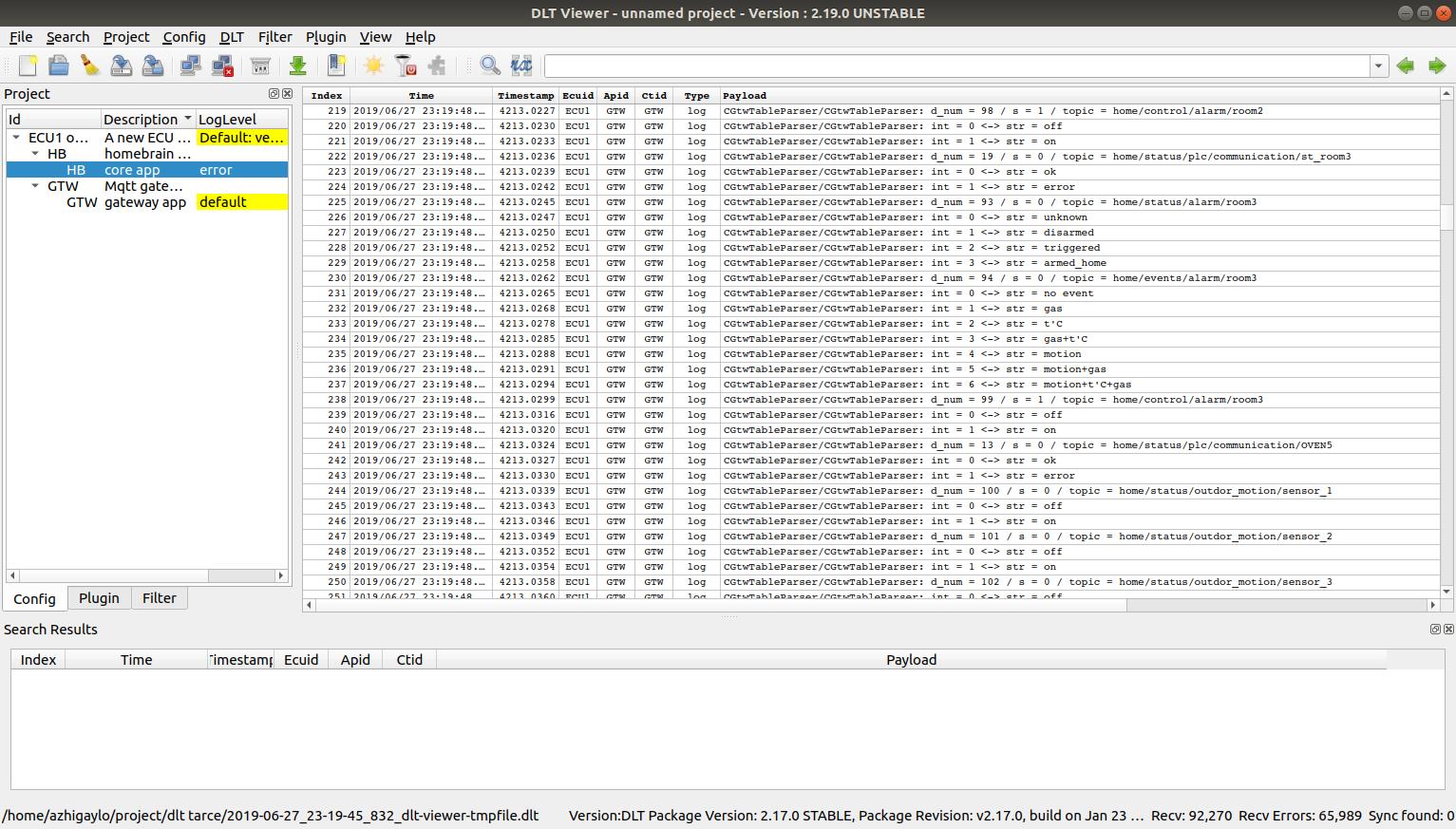
Choosing a system for collecting traded debits.
As you know, systems without bugs do not exist, as well as the analysis of a multithreaded system without traces. It is very convenient if these traces are not displayed simply in the console, but are collected using something specially created for this, so that it would be possible to sort them by processes, apply filters, etc. And I just know one good system that is easy to build under both host and target. This is DLT, if you have never heard of this, then it does not matter, all knowledge gaps can be easily covered by reading at.projects.genivi.org/wiki/display/PROJ/Diagnostic+Log+and+Trace .
This system consists of dlt-daemon and dlt-viewer. As the name implies, dlt-daemon runs on the target, and dlt-viewer on the host. Plus to all this, to your binary, from which we want to collect traces, you need to link the dlt lib.
In general, everything is convenient, how to collect traces and analyze them, I recommend.
Writing a build system.
Why write a build system, because you can download everything from the repositories, build it with your hands, build on the basis of this rootfs and veil, the controller works. But to repeat such a trick in a month will be more difficult, and in two - this is generally impossible. Again, you have to remember what, where to put, what to build and how to start. Therefore, having spent a lot of time at first, you save it later, plus you get the opportunity to conveniently build under host and target. The build system consists of a set of scripts that first prepare the host for the build, download third-party components, such as buildroot, mosquitto, DLT daemon, from their repositories, build them, put them in their places. And then you can launch the build of your project. If the build under the host is not difficult to do, then you always need to tinker with the build under the target, and it would be better if the script does it.
Buildroot can be configured so that it invokes a post-build script after it forms rootfs, which will lie in buildroot / output / target. This gives you a great opportunity to put everything you need there. And then, the file system image will already contain everything you need to start your system.
The recipe is something like this:
- you need to copy your binaries somewhere in buildroot / output / target, for example in / opt / bin
- if there are configs, then do the same with them, only in / opt / etc
- copy third-party binaries, for me it's mosquitto, DLT daemon, their libs and configs
- In order to start the system itself when loading the controller, you need to copy your systemd services, it is better to combine them into your target and reenable it by making a symlink in multi-user.
- copy the modified fstab (why, I'll tell you later)
After that, you just need to unpack buildroot / output / images / rootfs.tar to the desired section of the SD card and turn on the power.
build git repo: https://github.com/azhigaylo/build
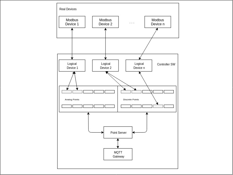
Writing a communication core.
The concept of this is as old as modbus itself.
Each I / O device in a modbus network has registers (16 bit) available for reading, reading / writing, in which data is stored and through which these devices are controlled. The controller, in turn, has arrays of discrete (status and byte value) and analog points (status and float value), in which it stores the state of all parameters.
So, the task of the communication core is simple - to collect data from I / O devices using the modbus protocol, map them to controller points and provide access to these points for the upper level. And if you need to manage something, then everything is in the other direction - the logical device (more on that later) must be subscribed to the controller point and writing to this point initiates the translation of this parameter to the physical water-output device.
In order to somehow structure the data and work with devices, you can introduce the concept of a logical device that will display the state of a physical device in your software.
I also decided to divide the logical devices into two groups:
- Standard (Aries modules of discrete input / output), for which the numbers of modbus registers with data are known in advance, and it is enough just to determine the controller points where to save this data.
- User devices, for them it is necessary to independently describe the mapping of modbus registers to controller points.
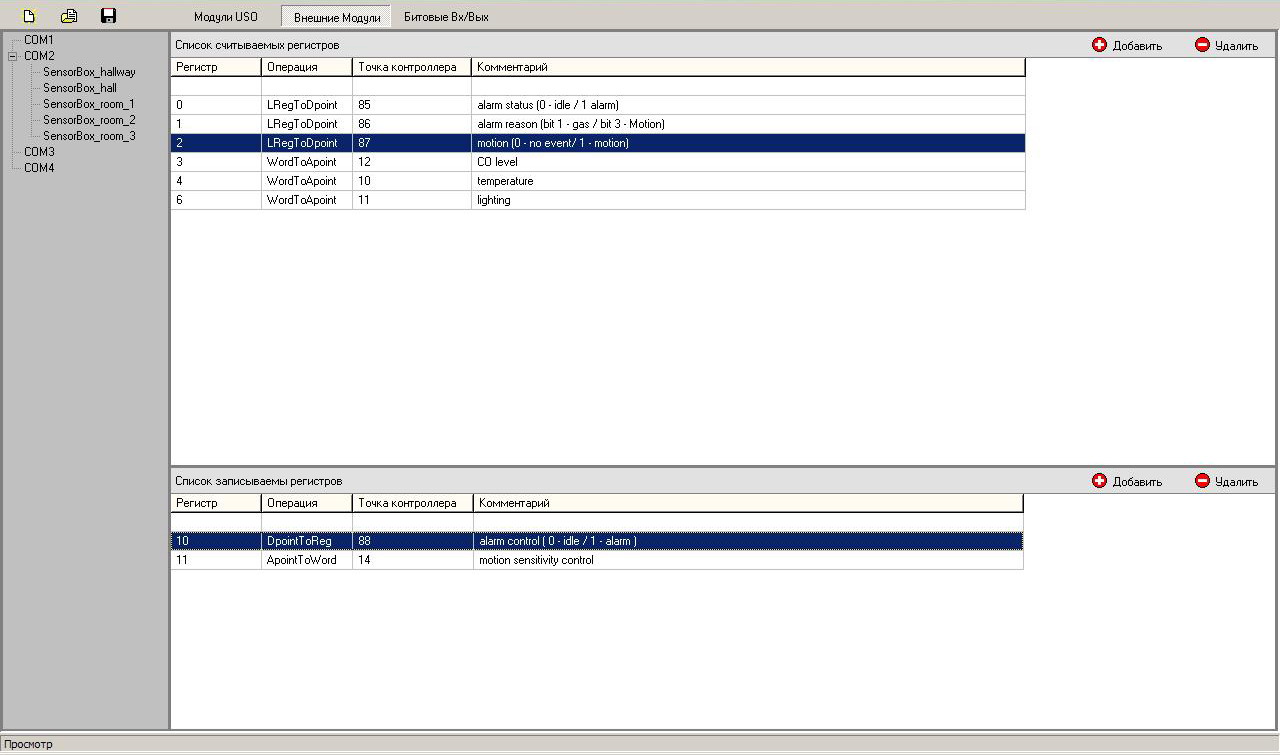
From all of the above, it’s logical to have some kind of configurator for the controller, whether it’s just a json config or a self-written tool generating a binary config, anything suits. I have the second option, because there were ideas to write a communication core so that it could be easily run not only on the Linux board but also on Arduin with FreeRtos, changing the PAL level in the software.
In the configurator for each device, you need to set the controller port number rs485, the device address, and the controller point to which the status of communication with the device is displayed, plus for each standard device its channels are described, and for the user device, its registers are mapped to points.
Such a configuration file, containing all the necessary data on the construction of the modbus network, allows you to not modify the source code for the project if you need to add / remove / change I / O devices, just change the parameters in the configurator and save them in the config file.
At startup, the communication core parses the config and creates on its basis lists of logical devices for each rs485 port of the controller, then threads are created on each port and a cyclic polling of physical devices begins.
core git repo: https://github.com/azhigaylo/homebrain_core
Writing mqtt gateway.
Actually - your controller points, both discrete and analog, with a proprietary interface for access to them, are of little interest to anyone. So there is only one way out - mqtt. I think I will not exaggerate if I say that this is currently the most common protocol for exchanging small messages, plus it is very simple and understandable to use. So when I needed to broadcast data from the controller - I did not think long about what to use.
Because I have a lot of parameters, then there were constantly confusions in the gateway configuration file, where the mapping of controller points to mqtt gateway topics was registered. Google helped the table, and writing the csv parser of this table in the json configuration file for the gateway.
gateway git repo
parser git repo
Writing point monitor.
Sometimes it’s very useful to see what is happening with the controller points, for this I wrote a small application that connects directly to the communication core and reads the status of discrete and analog points. I’m pretty tight with the UI, so I was able to somehow throw the application into QML, it worked with a squeak, you can count the point, you can record it, but I don’t need more.
pointmonitor git repo: https://github.com/azhigaylo/pointmonitor
Mount readonly file system.
Usually, few people pay attention to this, and even in production projects, you can find devices in which the partition with rootfs is writable. This sooner or later leads to the crash of any, even the most stable file system. Because Since the controller can be turned off at any time, it is only a matter of time / case when this happens. To minimize this probability, you need to tinker a bit with fstab and put the rootfs image there before putting the image, as described above. In fstab, firstly, you need to mount the file system as readonly, and secondly, everything that can change can be mapped into tmpfs.
My fstab is this, it may differ for you:
/dev/root / auto ro 0 1 tmpfs /tmp tmpfs nodev,nosuid,size=50M 0 0 tmpfs /srv tmpfs nodev,size=50M 0 0 tmpfs /var/log tmpfs defaults,noatime,size=50M 0 0 tmpfs /var/tmp tmpfs defaults,noatime,size=50M 0 0 tmpfs /var/run tmpfs defaults,noatime,size=50M 0 0 tmpfs /var/lib tmpfs defaults,noatime,size=10M 0 0
Controller body
The 3D printer has long been included in the masthead sections for each collective farmer engineer, unfortunately I do not have it, but it is at work. Recently, the excitement of other employees for him has disappeared, I use this when printing everything I need and do not need, you could be convinced of this by reading my previous post.
We draw in FreeCAD, we generate the gcode in Cura and we get a case, without forgetting to make seats for the board, cutouts for connectors and cooling and mortgages for clips on a din rail.
Well, that’s all, now we have a board, software on an SD card and a case. We take a file (I’m not joking) and connect everything together, connect the power, RS485 cables and everything starts to work. And you said difficult, difficult ...
All Articles