はじめに
バイナリ検索アルゴリズムを介して整数の整数立方根を計算するための合成可能なベリログコードを作成しました。 このコードは、Cyclone IV FPGAボードでテスト済みです。 ここでは、実装について読み、物事の仕組みを理解できます。
Githubリンク: キューブルート
キューブルートとは
数値yの立方根は、次のような数値xです。
$$表示$$ x ^ 3 = y $$表示$$
例:
$$表示$$ \ sqrt [3] {8} = 2 \\ \ sqrt [3] {27} = 3 \\ \ sqrt [3] {64} = 4 $$表示$$
そのため、実装では整数キューブルートを使用します。
これは、整数xの立方根が、次のような別の整数aであることを意味します。
$$表示$$ a ^ 3 \ leqslant x、\\(a + 1)^ 3 \ geqslant x $$表示$$
例:
$$表示$$ \ sqrt [3] {26} = 2 \\ \ sqrt [3] {28} = 3 \\ \ sqrt [3] {63} = 3 \\ \ sqrt [3] {65} = 4 $$表示$$
メインロジック
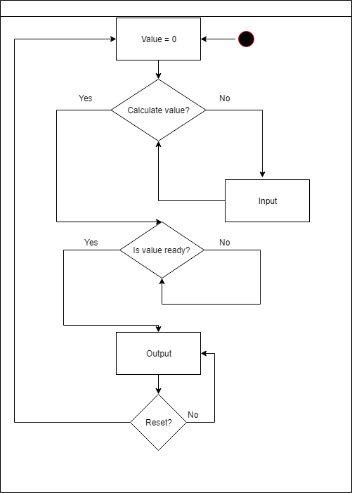
メインモジュールは、入力中の番号を持つすべてのアクションを担当します。
4つの可能なアクションがあります。
- インクリメントに10を掛ける
- 増分を10で除算します(増分は常に1以上です)
- 数を増やす
- 数を減らす
メインモジュール
module cube_root( input inc, input sub, input next, input prev, input enter, input clk, output wire [7:0] leds, output wire [7:0] control ); reg signed [31:0] exit; wire ready; wire [31:0] res; reg zero = 0; // input // reg inc1 = 0; reg next1 = 0; reg prev1 = 0; reg sub1 = 0; reg enter1 = 0; reg [31:0] decimal = 1; ////////// reg [31:0] to_display; display_bcd display( .clk(clk), .value(ready == 0 ? exit : res), .control(control), .leds(leds) ); calculate calc( .clk(clk), .ready_to_calc(~enter), .num(exit), .ready(ready), .res(res) ); always @(posedge clk) begin if (enter == 1) begin if ((inc1 == 1'b0) && (~inc == 1'b1)) begin exit = exit + decimal; end inc1 = ~inc; if ((sub1 == 1'b0) && (~sub == 1'b1)) begin if (exit > 0) begin exit = exit - decimal; end end sub1 = ~sub; if ((next1 == 1'b0) && (~next == 1'b1)) begin decimal = decimal * 10; end next1 = ~next; if ((prev1 == 1'b0) && (~prev == 1'b1)) begin if (decimal >= 1 && decimal <= 9) begin decimal = 1; end else begin decimal = decimal / 10; end end prev1 = ~prev; end else begin if (ready == 1'b1) begin exit = 0; decimal = 1; end end end endmodule
メインモジュールcube_rootには、 calculateとdisplay_bcdの 2つのモジュールもあります。 最初のモジュールはすべての必要な計算を行い、2番目のモジュールはプログラムの実行中に入力値と出力値を表示します。
それでは、それらの仕組みを理解しましょう。
計算モジュール
計算モジュールは、バイナリ検索アルゴリズムを使用します。 そして、すべての計算が完了すると、 ready変数が1に設定されます。これは、ディスプレイモジュールが回答を出力するための信号です。
計算モジュール
module calculate( input clk, input ready_to_calc, input [31:0] num, output reg ready, output [31:0] res ); integer mid; integer start; integer final; integer counter; assign res = mid; always @(posedge clk) begin if (ready_to_calc == 1) begin if (ready == 0) begin mid = (start + final )/2; if ((mid*mid*mid) > num) begin final = mid; end else begin start = mid; end if (counter == 27) begin ready = 1; counter = 0; end else begin counter = counter + 1; end end end else begin final = 465; start = 0; ready = 0; counter = 0; end end endmodule
このモジュールが正確に27回の繰り返しを行う理由
-最大入力数は99999999です。したがって、可能な最大反復回数は $インライン$ \ log_2 99999999 = 26.575424745 \約27 $インライン$
バイナリ検索の上限が465で初期化されるのはなぜですか?
-これは最大数であるため、結果として取得できます。 $インライン$ \ sqrt [3] {99999999} \約464 $インライン$
ディスプレイモジュール
このモジュールはパフォーマンスを担当します。 8つの8セグメントディスプレイを8つ使用し、16ピンで操作します。 ディスプレイ上の特定のLEDに対して8つのピンが「担当」であり、他の8つのピンが制御セグメントである場合、それらは個別の数字を表します。
そのため、このモジュールに表示したい整数値を渡します。 次に、この値をBinary_to_BCDモジュールに渡します。このモジュールは、 Double Dabbleアルゴリズムを使用して、2進数を2進化10進数に変換します 。 その後、変換された値は表示しやすくなります。
ディスプレイモジュール
module display_bcd ( input clk, input [31:0] value, output [7:0] control, output [7:0] leds ); bcd_convert #(32, 8) bcd_convert( .i_Clock(clk), .i_Binary(value_temp), .i_Start(1'b1), .o_BCD(bcd_number), .o_DV(bcd_ready) ); integer delay = 0; integer final_bcd; reg [2:0] ctrl = 0; reg [4:0] digit; wire bcd_ready; wire [31:0] bcd_number; wire [31:0] digits; assign digits = final_bcd; wire [31:0] value_temp; assign value_temp = value; assign control = ~(1 << ctrl); assign leds = ~ (digit == 0 ? 8'b00111111 : (digit == 1 ? 8'b00000110 : (digit == 2 ? 8'b01011011 : (digit == 3 ? 8'b01001111 : (digit == 4 ? 8'b01100110 : (digit == 5 ? 8'b01101101 : (digit == 6 ? 8'b01111101 : (digit == 7 ? 8'b00000111 : (digit == 8 ? 8'b01111111 : (digit == 9 ? 8'b01101111 : 8'b00000000)))))))))); always @(posedge clk) begin if (bcd_ready) final_bcd = bcd_number; case(ctrl) 0: digit = digits[3:0]; 1: digit = digits[31:4] ? digits[7:4] : 10; 2: digit = digits[31:8] ? digits[11:8] : 10; 3: digit = digits[31:12] ? digits[15:12] : 10; 4: digit = digits[31:16] ? digits[19:16] : 10; 5: digit = digits[31:20] ? digits[23:20] : 10; 6: digit = digits[31:24] ? digits[27:24] : 10; 7: digit = digits[31:28] ? digits[31:28] : 10; endcase delay = delay + 1; if (delay == 10000) ctrl = ctrl + 1; end endmodule
Bcd変換
module bcd_convert #(parameter INPUT_WIDTH, parameter DECIMAL_DIGITS) ( input i_Clock, input [INPUT_WIDTH-1:0] i_Binary, input i_Start, output [DECIMAL_DIGITS*4-1:0] o_BCD, output o_DV ); parameter s_IDLE = 3'b000; parameter s_SHIFT = 3'b001; parameter s_CHECK_SHIFT_INDEX = 3'b010; parameter s_ADD = 3'b011; parameter s_CHECK_DIGIT_INDEX = 3'b100; parameter s_BCD_DONE = 3'b101; reg [2:0] r_SM_Main = s_IDLE; // The vector that contains the output BCD reg [DECIMAL_DIGITS*4-1:0] r_BCD = 0; // The vector that contains the input binary value being shifted. reg [INPUT_WIDTH-1:0] r_Binary = 0; // Keeps track of which Decimal Digit we are indexing reg [DECIMAL_DIGITS-1:0] r_Digit_Index = 0; // Keeps track of which loop iteration we are on. // Number of loops performed = INPUT_WIDTH reg [7:0] r_Loop_Count = 0; wire [3:0] w_BCD_Digit; reg r_DV = 1'b0; always @(posedge i_Clock) begin case (r_SM_Main) // Stay in this state until i_Start comes along s_IDLE : begin r_DV <= 1'b0; if (i_Start == 1'b1) begin r_Binary <= i_Binary; r_SM_Main <= s_SHIFT; r_BCD <= 0; end else r_SM_Main <= s_IDLE; end // Always shift the BCD Vector until we have shifted all bits through // Shift the most significant bit of r_Binary into r_BCD lowest bit. s_SHIFT : begin r_BCD <= r_BCD << 1; r_BCD[0] <= r_Binary[INPUT_WIDTH-1]; r_Binary <= r_Binary << 1; r_SM_Main <= s_CHECK_SHIFT_INDEX; end // Check if we are done with shifting in r_Binary vector s_CHECK_SHIFT_INDEX : begin if (r_Loop_Count == INPUT_WIDTH-1) begin r_Loop_Count <= 0; r_SM_Main <= s_BCD_DONE; end else begin r_Loop_Count <= r_Loop_Count + 1; r_SM_Main <= s_ADD; end end // Break down each BCD Digit individually. Check them one-by-one to // see if they are greater than 4. If they are, increment by 3. // Put the result back into r_BCD Vector. s_ADD : begin if (w_BCD_Digit > 4) begin r_BCD[(r_Digit_Index*4)+:4] <= w_BCD_Digit + 3; end r_SM_Main <= s_CHECK_DIGIT_INDEX; end // Check if we are done incrementing all of the BCD Digits s_CHECK_DIGIT_INDEX : begin if (r_Digit_Index == DECIMAL_DIGITS-1) begin r_Digit_Index <= 0; r_SM_Main <= s_SHIFT; end else begin r_Digit_Index <= r_Digit_Index + 1; r_SM_Main <= s_ADD; end end s_BCD_DONE : begin r_DV <= 1'b1; r_SM_Main <= s_IDLE; end default : r_SM_Main <= s_IDLE; endcase end // always @ (posedge i_Clock) assign w_BCD_Digit = r_BCD[r_Digit_Index*4 +: 4]; assign o_BCD = r_BCD; assign o_DV = r_DV; endmodule // Binary_to_BCD
著者:テューリンレオニード、ティホノフニキータ。