Recently, two completely different worlds converged in our laboratory: the world of low-cost radio transceivers and the world of expensive systems for recording broadband radio signals.
First, our good friends turned to us to make software for recording a signal with a band of 500 MHz. Of course, we could not refuse. After all, it was necessary to do this on the board of the company "Instrumental Systems", which I have known for a long time. At the dawn of engineering, I had to work with their hardware and software.
And then my dear friend mikkab came from the Drones Show and asked for a positioning system for drones without GPS. It is necessary, he says, to run the show on the premises. And on the street in our time, I don’t really want to launch several million money on unreliable GPS into the sky. Interference and spoofing of satellite navigation are booming .
For positioning without satellites with an accuracy of better than ten centimeters in the area up to a kilometer, I did not find anything other than UWB technology. For a long time there has been a DecaWave company on the market that produces the DW1000 chip and modules based on it. Chip - UWB transceiver of IEEE 802.15.4-2011 standard. By the way, the thing is unique, with a double or even triple bottom. I hope we can master its depth in the next few years and write about it. Formerly not to be in time.
But today we are not talking about positioning, about this in the next series.
Today we are recording the DW1000 signal. And the band of this signal is neither more nor less, but 1000 or 500 MHz, which is set by the channel number. “Quite by chance” on the next table was a computer with the FMC126P board from Instrumentation Systems and the FM9 mezzanine AD9208-3000EBZ from Analog Devices.
It should be noted "for the prosecutor" that the AD9208 ADC is today a sanctioned technique. You can’t legally buy it in Russia, although sometimes you really want to. But this particular module was purchased a long time ago, when there were no sanctions. He is pure as the soul of a baby. I hope that this confession will be filed to the case and credited to the defendant.
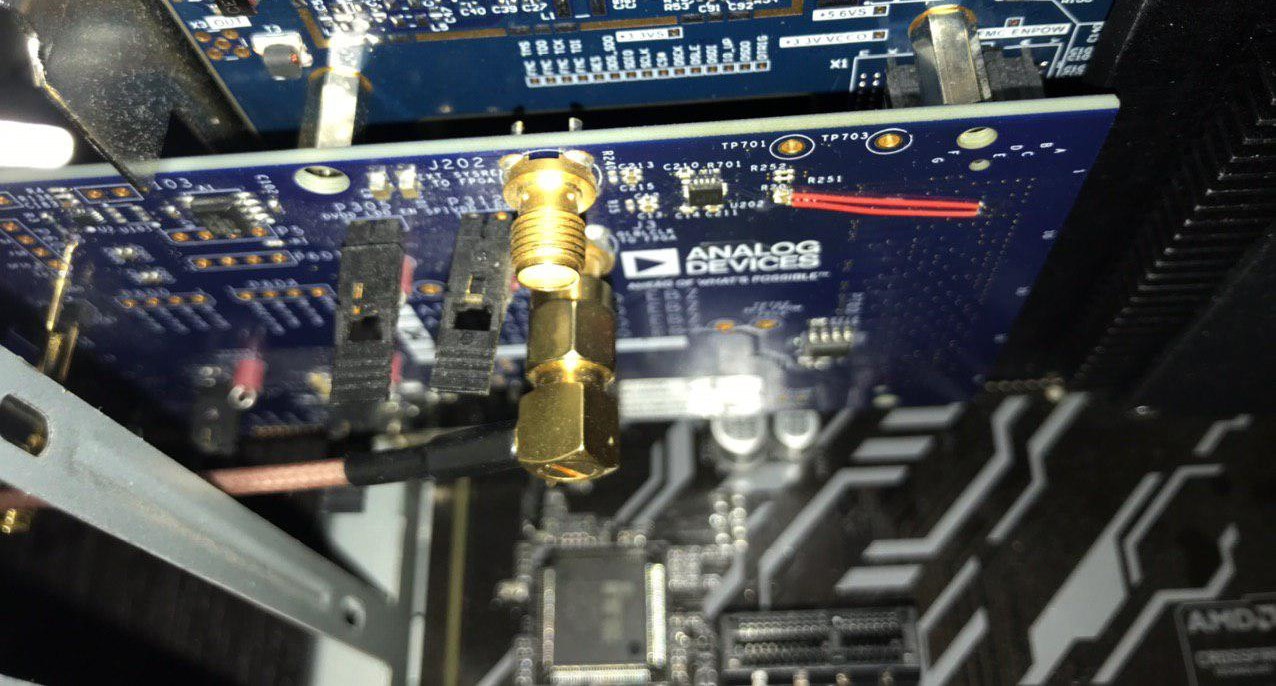
We will not go into the details of developing software for recording the stream of samples in the computer’s memory. So far, unfortunately, we cannot publish the source code of the application for Linux. But we hope to get permission for this next time. It should only be noted that this was not easy, even taking into account the provided software developments of Tooling Systems. The ADC itself and its clocking and sampling system using the JESD204B technology are quite difficult to understand, and also hardware patches were needed in the AD module. The REFCLK signal is necessary for the input system, but it enters the wrong feet of the FMC connector on the module and, accordingly, does not fall on the necessary legs of the FPGA. I had to apply a patch, which can be seen in the photo below - two red wires. There were, of course, doubts that this would work. The clock frequency is high - 375 MHz, and the patch is terrible. But the system did it.
The whole kitchen looks like this.
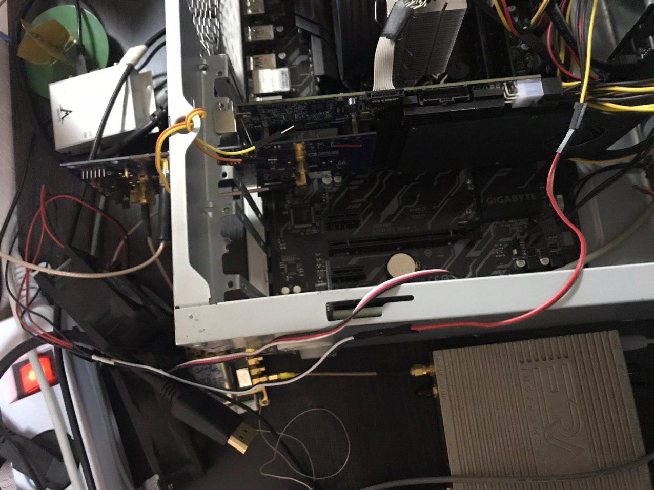
Here you can see a computer with a good I / O system, an FMC126P board, an AD9208-3000EBZ mezzanine. From the generators: a 3000 MHz generator for ADC clocking, a 770 MHz generator for REFCLK. Cables with SMA connectors connect the generators and provide an input signal.
Raw data rate from the output of the ADC, if not trifle, is 12 GB / s from two channels. According to measurements and according to the manufacturer’s declaration of the FMC126P board, the maximum input speed is 5 GB / s. Therefore, in the ADC, we used only one channel and passed it through the built-in AD9208 DDC (Digital Down Converter) with a decimation of four. Thus, the data stream amounted to 3 GB / s (sampling frequency 750 MHz, 16 bit complex signal).
Checking that the system manages to record samples is very simple: you just need to control the sticky bits of the FIFO FPGA status. If there were no FIFO Overflow events during the night, then the bit will not be cocked. And we joyfully state that there were no loss of readings. First of all, of course, we check that fixing the status bits works. We also look at the waveform from the file to make sure that the quality of the ADC signal pickup corresponds to the documentation.
But what signal would be worthy of such an input system? Of course UWB from the next table!
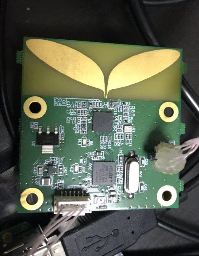
Fortunately, for the drone positioning system, we chose a 4 GHz channel frequency. This corresponds to channels 4 and 2 in DW1000 terminology (Figure 13 datasheet). We made an antenna built into the board for this frequency, or, rather, for this range. Coordinating it in such a wide band was not easy. But the thing turned out erotic! Some say it looks like a symbol ... with ears.
A 4 GHz signal with a band of 500 MHz falls into the third Nyquist band and has sufficient guard intervals to avoid spectrum overlap. Therefore, we simply applied the DW1000 signal to the AD9208 ADC input directly.
We got two files: one with a PRF frequency of 64 MHz, the other - 16 MHz. The transfer rate was set to the minimum for the DW1000 - 110 kbit / s.
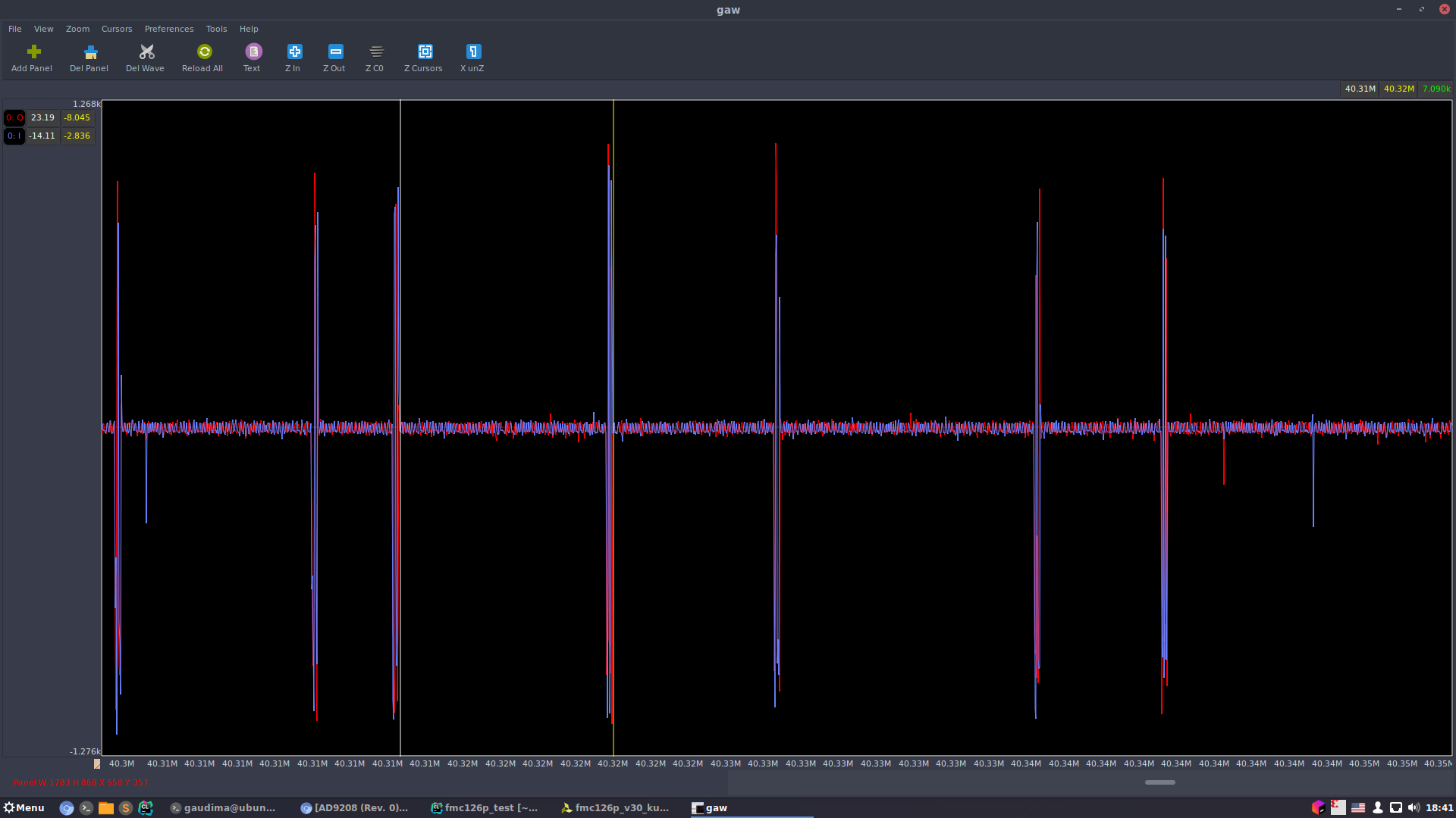
This is the first file, this is the second . Caution, the files are huge!
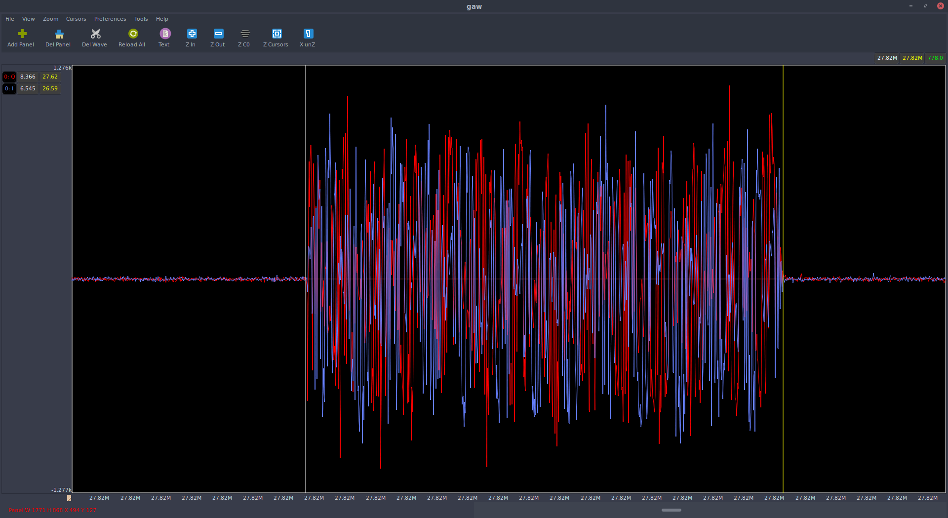
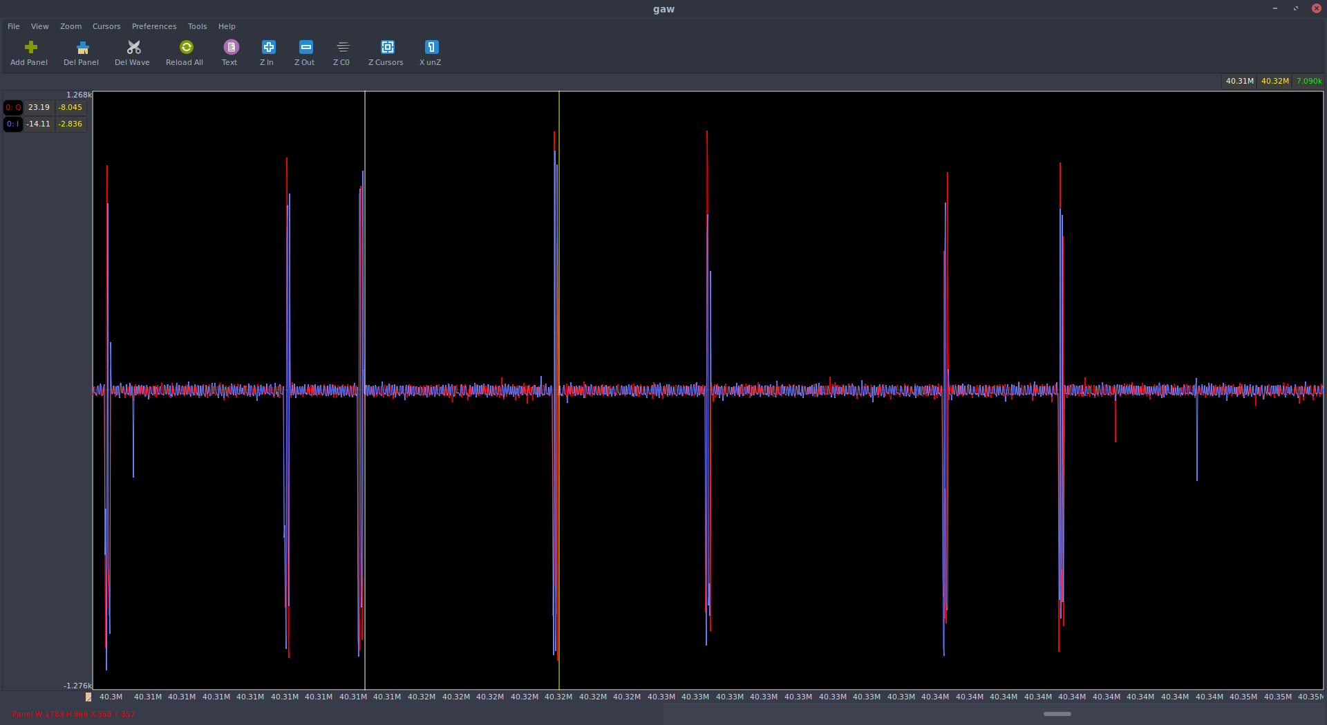
In the first file we see packets with a duration of about 750 samples or 1000 nanoseconds.
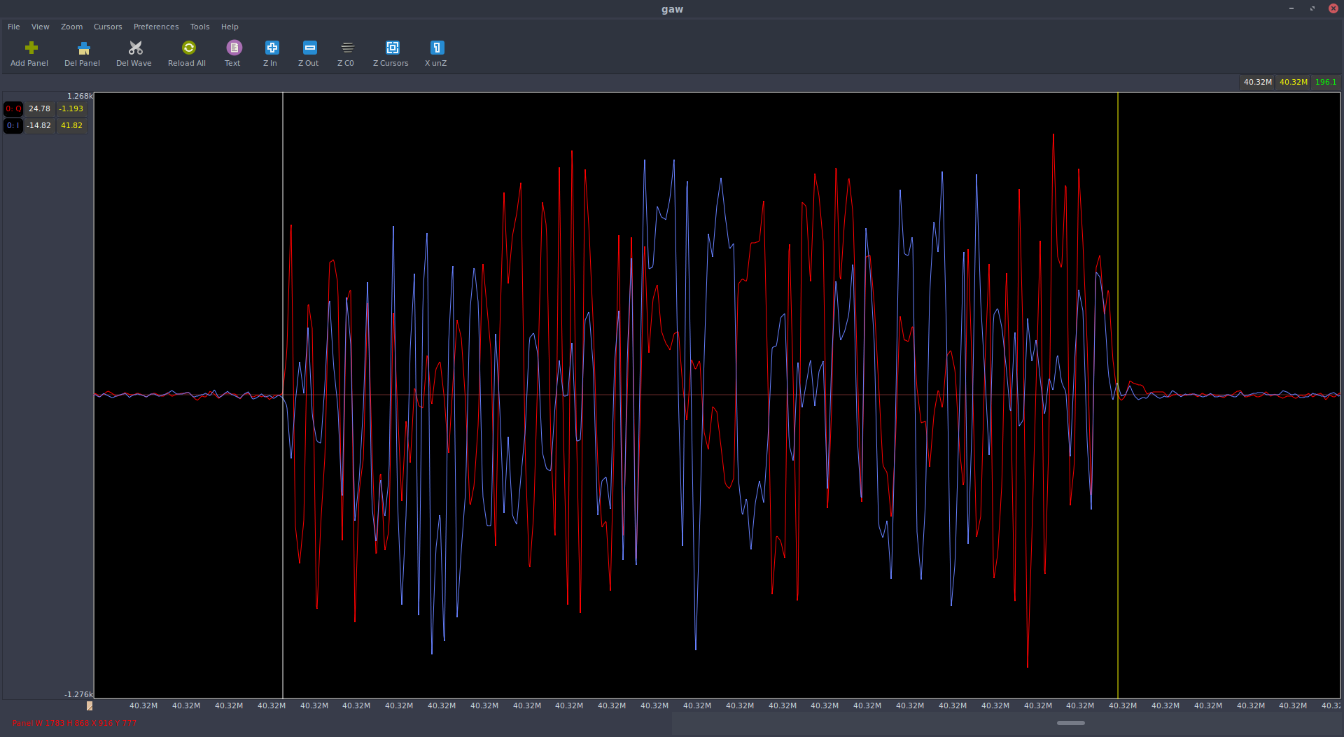
In the second file, packages are four times shorter.
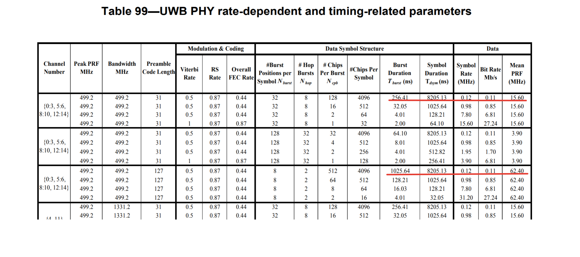
And this is fully consistent with the IEEE 802.15.4-2011 standard in terms of the physical layer of UWB:
Modulation inside the package is similar to phase modulation, which also corresponds to the one specified in the BPSK standard. You can find the standard on the Internet, look for "IEEE 802.15.4-2011".
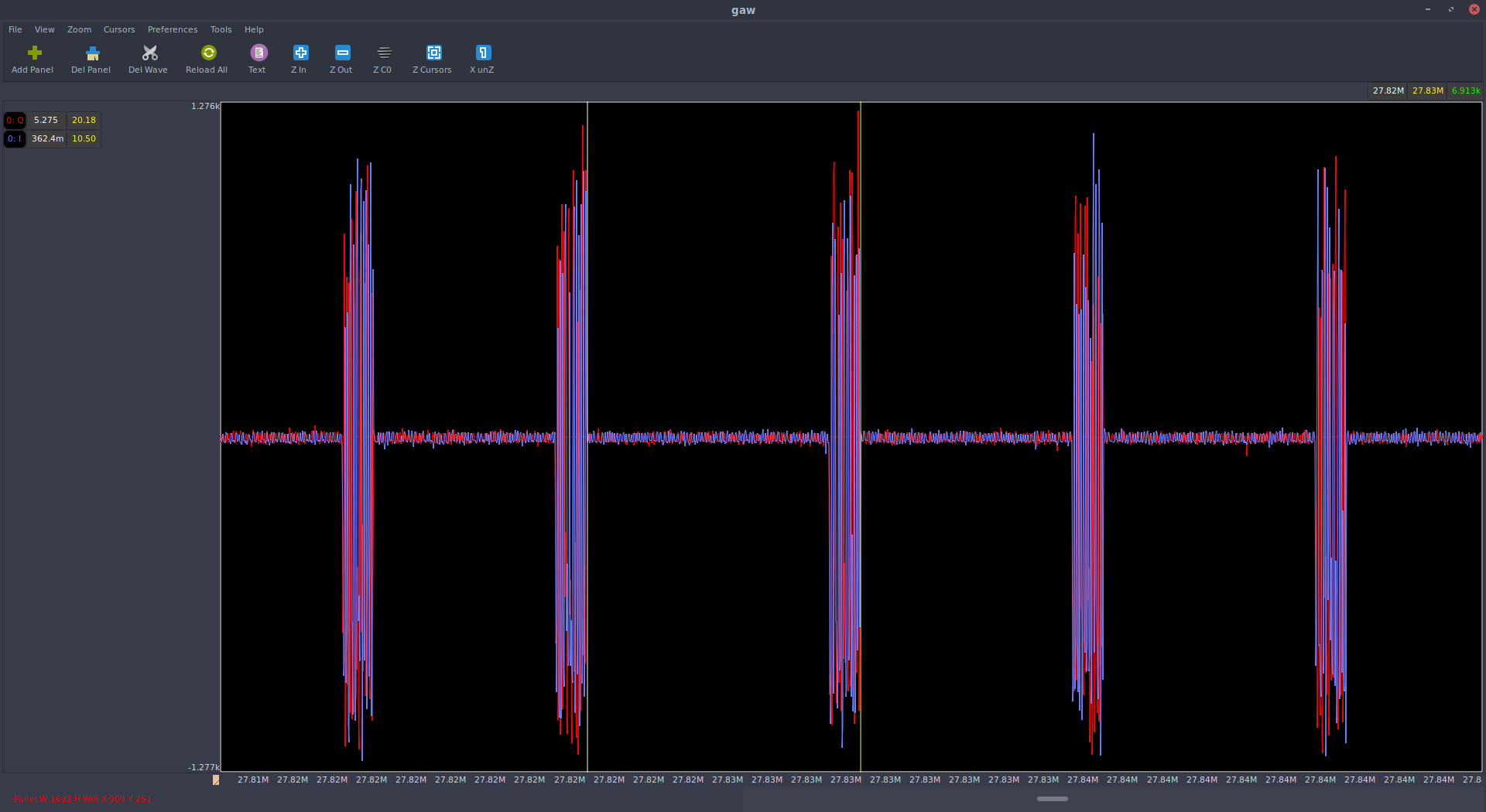
If you expand the time window of the observation a little, you can see the unevenness of packets, which corresponds to the description of the hybrid modulation IEEE 802.15.4-2011 UWB - position-phase (BPM-BPSK).
In general, I find the DW1000 chip and the modulation of this UWB PHY bombing, whatever that means, at the military JTIDS level. This is my new hobby. To be continued!
On the one hand, we will dig the DW1000, on the other, we will deal with the IEEE 802.15.4 standard.