
Most of the printed circuit boards that I was tracing are small-sized, with a high density of installation and the use of open-circuit microcircuits - this is the specifics of the development of ICS (English SIP), and in other cases they also managed to get by with electrically short lines. On one of the last boards, it was required to use asymmetric control lines with a length of about 15 cm, and in the specification for one of the microcircuits, the signal fronts t R were declared equal to 2 ns. Let me remind you (the article is here so as not to be repeated much) that the criterion for an electrically short line is:

where TD is the time delay of the line. I often met ½ in this formula, but the specified criterion is more stringent, therefore it is better to use it, and for the rest, apply modeling.
Obviously, the criterion is not met. I began to read about coordination and realized that I did not really like this section in the book . Just because in practice I seriously did not encounter this task. I began to understand and found a good article about matching, where, in particular, there are recommendations for matching for various types of signals. For CMOS signals, a sequential circuit was recommended, which, in fact, is logical.
The FPGA is used as a control chip in the project, so I decided to simulate the signal propagation in the line. For this task, IBIS models are used that contain a standardized description of the parameters of the input and output stages of microcircuits. Here is a good short article that gives a basic idea of the structure of IBIS models.
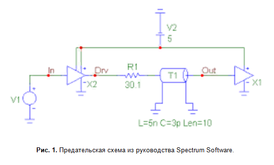
I downloaded the FPGA IBIS model from the manufacturer’s website, now I had to screw it to the transmission line and perform the simulation. The simplest and most affordable solution that I have found is to use the “good old” Micro-Cap, which is now absolutely free . Here I read a description of how to apply IBIS-models. Does not work. Well, I find the same IBIS model that the manual refers to, download, repeat the diagram (Fig. 1) already one-to-one. It still doesn't work.
I already thought about trying to perform modeling in Altium Designer, but I draw attention to the line in the text description of the component parameters (Fig. 2) - the active level of the resolution signal is low. I change the circuit, everything works, first 74AHC00, and then the FPGA IBIS model I need. Then it’s a matter of technology - there are video tutorials on using Micro-Cap.

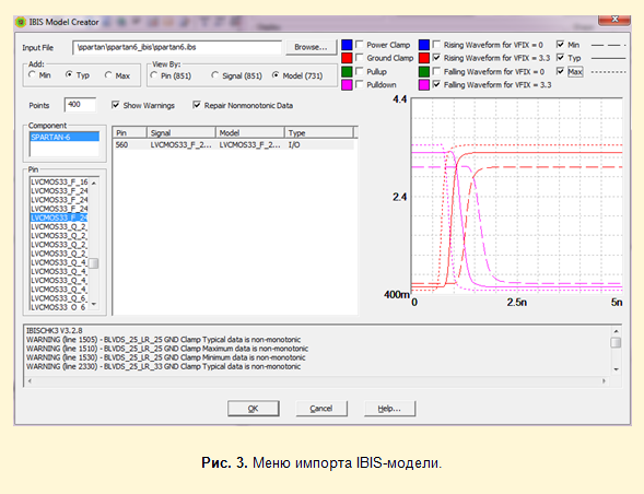
Adding an IBIS model to the circuit is quite simple with all the inconvenience of the Micro-Cap as a whole. Menu Component -> Analog Primitives -> IBIS -> IBIS_Output5 or IBIS_Input3. In the IBIS Model Creator menu that appears (Fig. 3), specify the path to the * .ibs model file and select a specific implementation. Here, the model parameters are graphically displayed - typical and ultimate.
Using the circuits shown in Fig. 4, driver output impedances for high and low voltage levels are determined. This is necessary to select a terminating resistor R SER = Z 0 - R OUT , here R OUT is the average value between R OH and R OL .

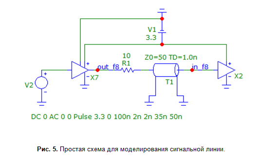
For FPGAs, output stages are configurable, therefore, in the IBIS model there are a huge number of options that differ in output type, voltage levels, load capacity, and front rise rate. I needed 3.3-volt CMOS, Xilinx has three types, depending on the length of the front - Fast, Slow and QueitIO. Going through the various driver options in a simplified signal line circuit (Fig. 5), I came to the conclusion that on the FPGA side I will manage the configuration and there is no need for additional terminating resistors.
PS The section on coordination in my guide will be finalized in the next release, as time appears. The process of cognition is endless. By the way, I found an import colleague with a similar leadership. He was well done and had a great project , but the book was not inspired. So I think that the task of import substitution in this particular case is successful :).