annotation
Madness All Ages Submissive
When designing any modules on FPGAs, the idea of not quite standard use of the design environment itself and the tools that it provides for design sometimes comes to mind. In this short article, we will look at how, with the help of the environmental management tool implemented on Tcl, we can literally draw photographs, paintings, portraits and memesics on the FPGA.
Such an unusual “design route” was implemented a year and a half ago, but only now the idea came to arrange it in the form of a note, in which there is little practice in using Tcl scripts to manage the design environment, in this case Vivado. However, with minor modifications, everything can easily be adapted to other development environments, for example Quartus II.

Introduction
Of course, the idea did not come to mind from nowhere. Its appearance was promoted by my then employment in projects on image processing and video stream management on FPGA. It happens to everyone that when sitting over a solution to a problem, every heresy comes to mind why it does not work or works exactly as it should, but not as we expect.
To solve the problem, I had to resort to one of the tools of the Vivado environment, namely, coloring the corresponding components and modules in the project after placement and tracing and peering into endless time charts.
As a result, I painted several configurable logical blocks of CLB in various colors, and it dawned on me - these are the pixels of the image, so I can try to draw which thread the picture, matching each pixel with my own colored CLB? ... well, it started
How will Tcl help us?
Suppose we have a small picture of size 100x100 pixels. Now suppose that in order to color the CLB, we need to do two things: select the CLB and select the color. In the 100x100 picture, we have 10,000 pixels and doing such a coloring manually is quite tedious, especially since the actions are the same and repetitive. Thus, manually painting each CLB is not an option and you need to use Tcl and scripts. But where to start?
The first thing that came to mind was to find the right team responsible for assigning color to the selected element. Fortunately, when manually performing actions, Vivado displays the appropriate Tcl commands to the console, and it seems that the search problem should be solved as quickly as possible. However, it was not there. Vivado simply ignores the output of the command to highlight the selected elements and the only way to find the command, and I was absolutely sure that it should be, is to plunge headlong into the Tcl guide available in Vivado, and this is almost 2000 pages [1].
Do not despair, the keyword "highlight" quickly found the corresponding command, which is called highlight_objects. This command highlights the specified or selected objects in a specific color, specified using options. The options for the highlight_objects command are as follows:
- color_index - (optional) the valid value of the option argument must be a number from 1 to 20. The color in which the selected object will be painted is determined by its serial number from the predefined color palette, which can be found in Colors → Highlight in the menu section Tools → Settings .
- rgb - (optional) sets the color of the selected object in RGB format
- color - (optional) highlights the selected object in one of the following colors: red, green, blue, magenta, yellow, cyan and orange
The remaining options of the command relate to the system settings of the command itself and will not be useful to us. However, when using the highlight_objects command, keep in mind that two or more coloring options cannot be applied at the same time.
Obviously, an option that sets an arbitrary color in RGB format is suitable for our task - the rgb option
Now it would not be bad to get the pixel values of the image, but I could not find the image that would be presented in bitmap format. Opening each file with a text editor, it was not possible to find lines with a pixel value. Of course, I did not write a program for converting images to bitmap format, but just climbed the Internet to look for a ready-made solution. Search did not have too long. As it turned out, the task of converting an image to a bitmap format (that is, when we see the pixel values of an uncompressed image) is quite relevant (probably, such a task is given to student-programmers as a homework for laboratory work). A short search resulted on github, from where the Image2Bitmap program [2] was downloaded.
The program requires an image input and outputs the pixel values in the form of a C array with hexadecimal pixel values in RGB565 format. This format says that the color coding for the red component uses 5 bits, green 6 bits and blue 5 bits. This turned out to be quite enough for work. Now all that is required is to map the obtained values directly to the sections to be painted (slice).
FPGA selection
The larger the FPGA, the more logical resources in it, and therefore the “field for creativity” itself is larger and the picture will be clearer. It should be noted right away that “decorating” is a rather long process and can take a decent amount of time, depending on the size of the image. For testing, it is worth choosing an FPGA with a small amount of resources. For example, the Spartan-7 family. After testing, you can change the FPGA to a more "fat", for example, from the Ultrascale + family.
We start Vivado and we create the project
We select the xc7s6cpga196-2 crystal, on which we will draw the test image

To display the drawn, we need to open the image of the crystal itself, however, this can be done after the synthesis stage or elaborate. In Vivado, for this we need to create a dummy module in any language.
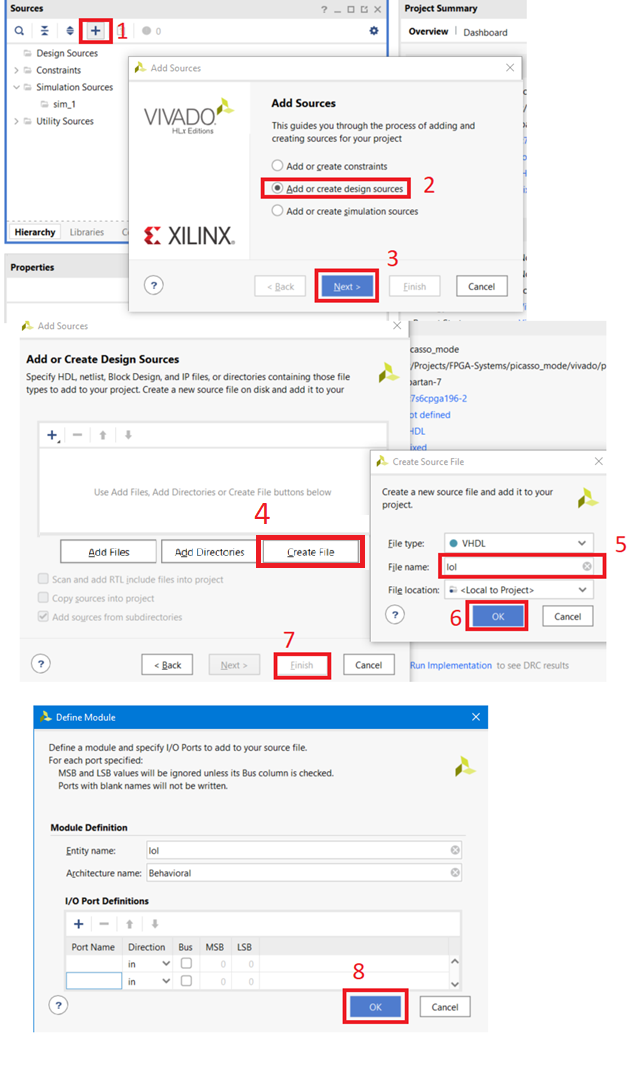
Add a script to the Tcl project.
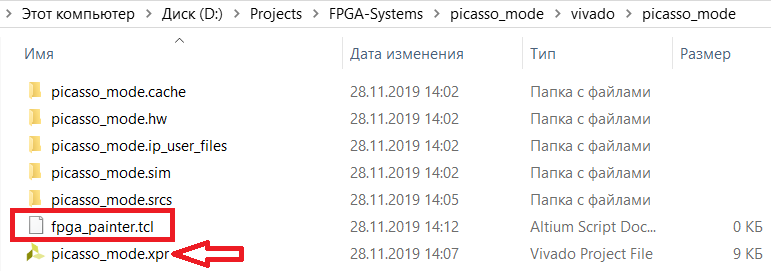
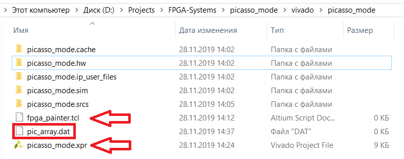
a. To do this, create a file with the extension “.tcl” in the folder with the project, for example, “fpga_painter.tcl”
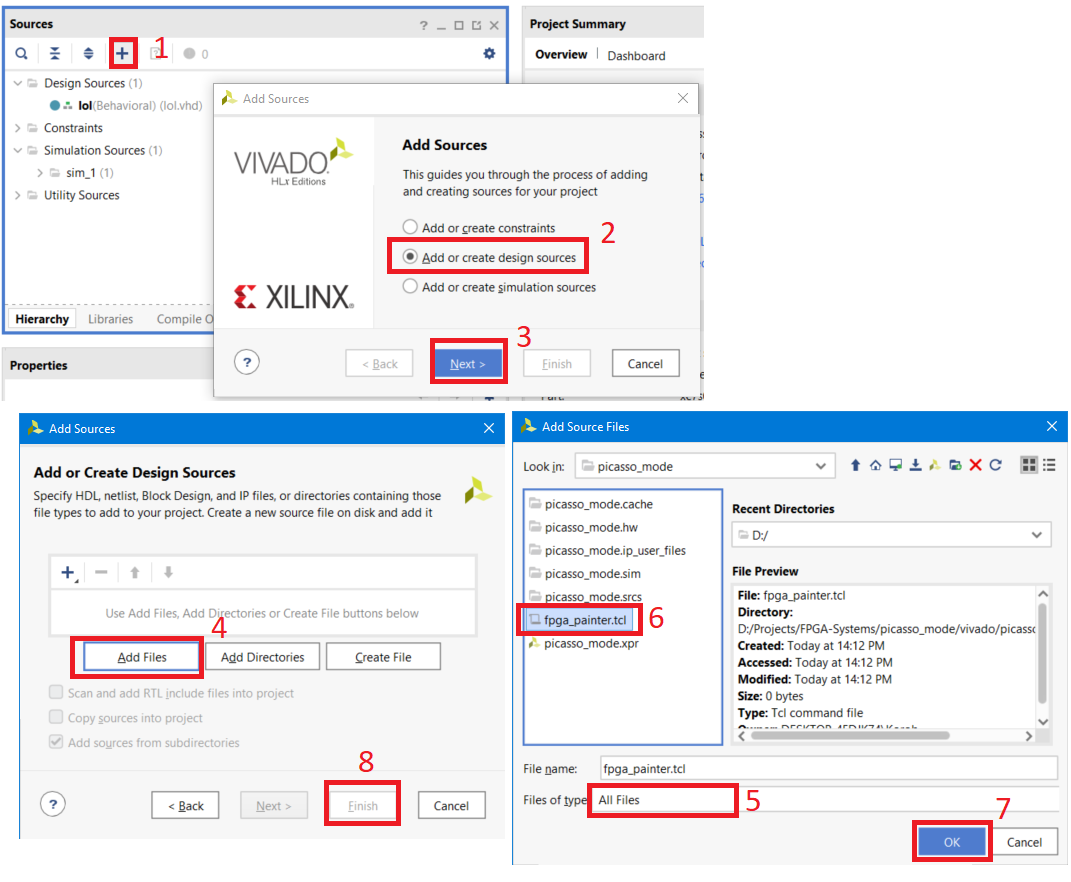
b. Go to Vivado, and add this file to the project.
c. After updating the project hierarchy, make the file inactive.

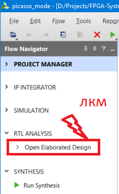
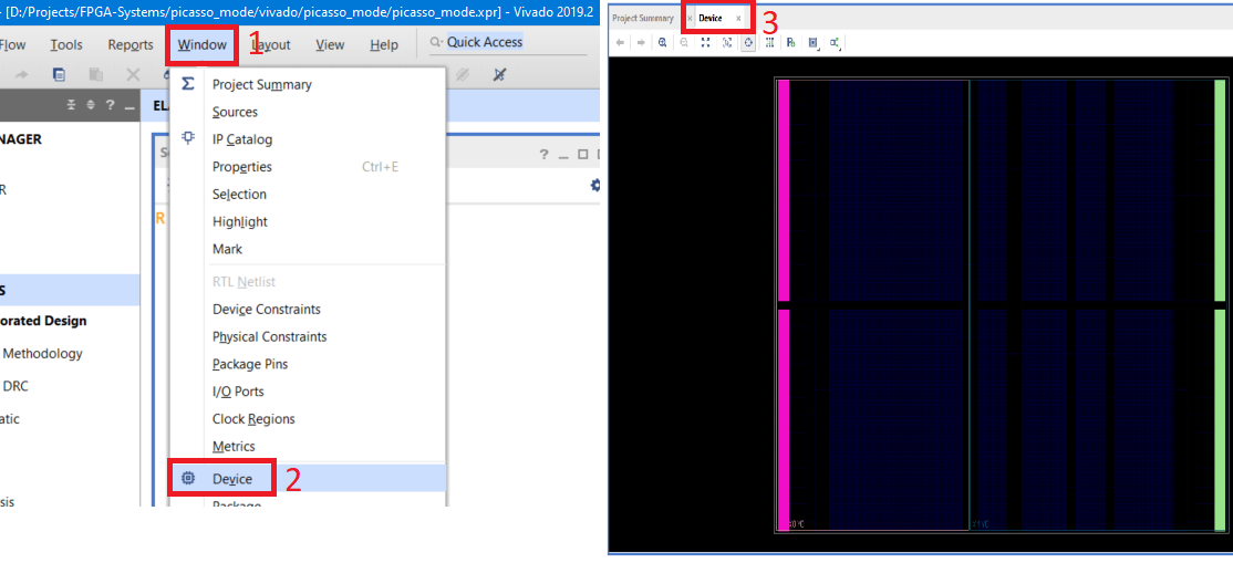
After creating the module, it will appear in the project hierarchy window and the Open Elaborate Design button will be available to us. Push it.
After opening Elaborate Design, go to Window → Device. A display of the field of our FPGA will appear.
Preparation is complete, we begin writing a script.
Definition of parameters and procedures
Test image
First, let's debug the algorithm / code as such on a small image, say 5x3, and then run it “to the fullest.”
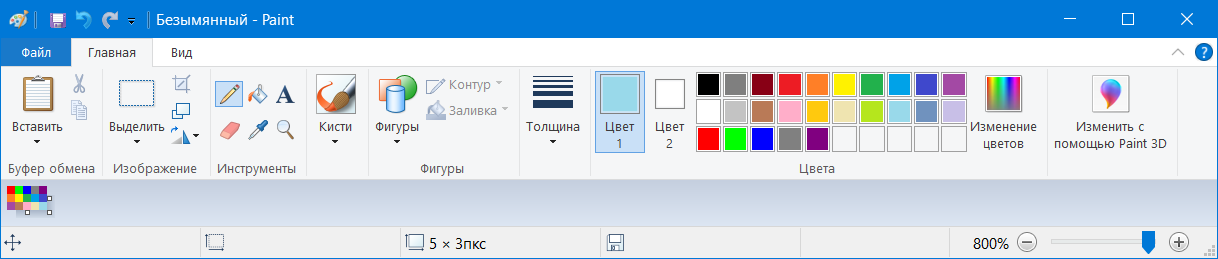
Open Paint, limit the image field to 5x3 pixels (you can take any colors). Save the file as “5x3.png”
Open the Image2Bitmap program and convert our image into an RGB565 array.
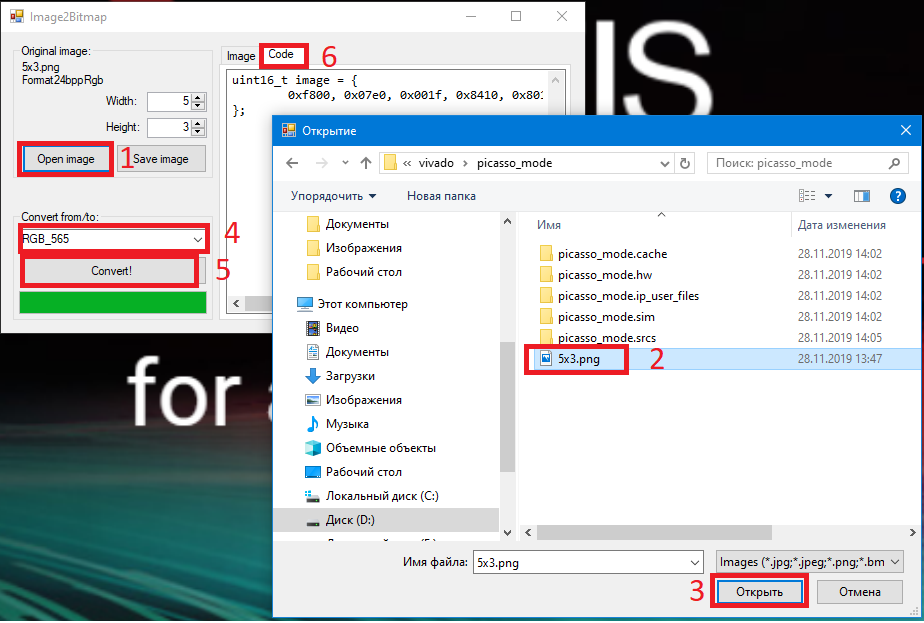
After conversion, the program will give us an array of 15 pixels
*uint16_t image = { 0xf800, 0x07e0, 0x001f, 0x8410, 0x8010, 0xfbe4, 0xff80, 0x2589, 0x051d, 0x3a59, 0xa254, 0xbbca, 0xfd79, 0xef36, 0x9edd, };*
Data preparation
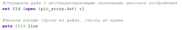
Before proceeding with the processing of pixels, we transform the data generated by Image2Bitmap into a simple list in which hexadecimal pixel values are written. We will copy the program data and save it in the pic_array.dat file, which should be located in the project folder.
When starting the created script, we have to process the file "pic_array.dat". It is worth noting that the number of elements in the line returned by Image2Bitmap does not match the number of pixels in the line of the converted image, for this reason we will create a separate list of "pixels".

When reading a file, you must ignore the first line "uint16_t image = {" and the last "};". To skip the first line when reading a file, simply place the line reading before the cycle of reading the entire file.
After reading the entire file, we will see that the last line of the file “};” has become an element of the list, which is simply deleted.

This completes the formation of the list with hexadecimal pixel values. Now let's start processing them.
Image Sizing
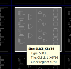
Once again, take a look at the FPGA field and the image. The FPGA field is divided into sections (SLICE), which have the corresponding horizontal coordinates “X” and vertical “Y”. For example, SLICE_X6Y36.
The image, in turn, has pixels, also with horizontal and vertical coordinates. When overlaying the image on the FPGA, we should combine the upper left pixel with the upper left section of the FPGA. In this case, the selected crystal has an upper section with the coordinate X0Y49.
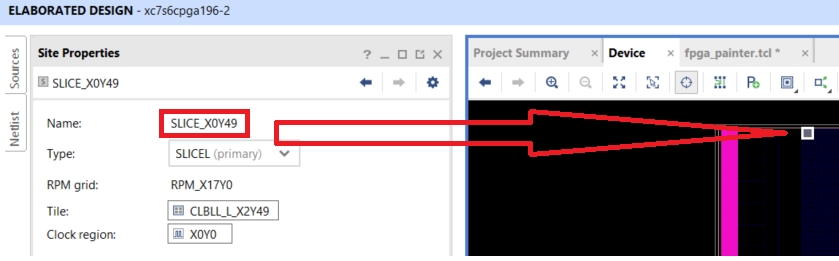
The image size will be determined by the number of sections in the FPGA horizontally and vertically. For the selected crystal, the horizontal coordinate of the sections varies from X0 to X131, and the vertical coordinate from Y49 to Y0. It follows that theoretically we can draw an image of size 132x50 on the selected crystal.
Initial parameters
To summarize: the initial parameters of our script will be:
X start axis position: variable name start_x

Section start position on the y axis: variable name start_y

Image Width (for test image is 5): w variable

Image height (for test image is 3): variable h

Pixel color adjustment
Image2Bitmap provides an array of pixels in RGB565 format as a 16 bit number written in hexadecimal format. We should:
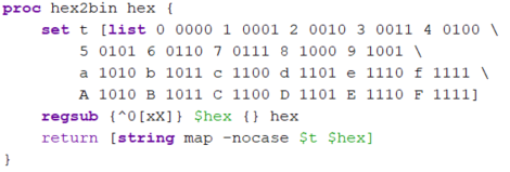
Convert pixel value to binary format. This can be done using the hex2bin procedure, which can be found in [3]
Match the bits to the corresponding color components:
• The red component of R [15:11]
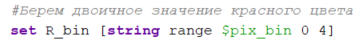
• Green component G [10: 5]

• Blue component B [4: 0]

Explanation: the order is changed due to the fact that the hex2bin procedure returns a line in which the numbering of elements begins with 0, that is, the 15th bit corresponds to the 0th element of the line, and the 0th bit is the 15th element of the line
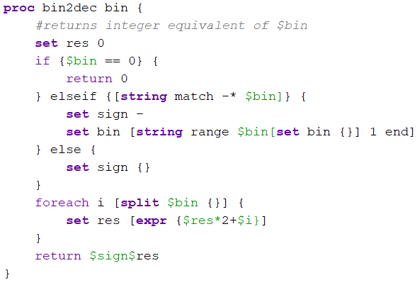
Convert the value of the color component from binary to decimal. This can be done using the bin2dec procedure, which can be found [3]:
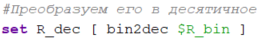
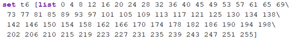
Convert pixel values from RGB565 to RGB888 format, for smoother image display. This is done using two lists, which can be found in [4]. How it works:
• The resolution of the color components R and B is 5 bits. Taking the decimal value of the component, we compare it with the position of the number written in the list t5, and the value of the component changes to the value in the table


• Similarly for component G and table t6

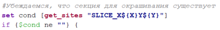
Section Availability
Inside some FPGAs there are special resources or voids that can disrupt the sequential numbering of the coordinates of the sections. For example, the figure below shows that the section numbering is interrupted (xc7s50 crystal)
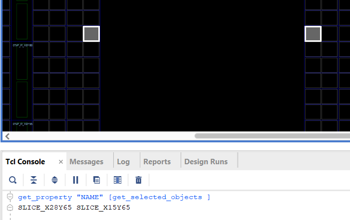
For this reason, before staining, we first check the existence of the section. If it exists, then paint, if it does not exist, then go to the next pixel
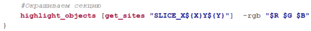
Section staining
Section color defined, section checked. Now the color needs to be assigned to the sections using the highlight_objects command:
Vector → Two-Dimensional Array
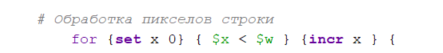
In the beginning, we converted the image data into a list of pixels, which stores a progressive scan of the image. To organize the picture, we introduce two variables, x and y, which will correspond to the position of the pixels in the image. By sequentially reading the elements of the list of pixels, we will form an image using two for loops: one by the number of lines, the second by the position of the pixel in the line

Full script listing
#https://tcl.tk/ #http://www.tune-it.ru/web/il/home/-/blogs/-rgb888-<->-rgb565----- #https://github.com/FoxExe/Image2Bitmap/releases/tag/0.5 # set start_x 0; # set start_y 49; # set w 5; # ( ) set h 3; # ( ) proc hex2bin hex { set t [list 0 0000 1 0001 2 0010 3 0011 4 0100 \ 5 0101 6 0110 7 0111 8 1000 9 1001 \ a 1010 b 1011 c 1100 d 1101 e 1110 f 1111 \ A 1010 B 1011 C 1100 D 1101 E 1110 F 1111] regsub {^0[xX]} $hex {} hex return [string map -nocase $t $hex] } proc bin2dec bin { #returns integer equivalent of $bin set res 0 if {$bin == 0} { return 0 } elseif {[string match -* $bin]} { set sign - set bin [string range $bin[set bin {}] 1 end] } else { set sign {} } foreach i [split $bin {}] { set res [expr {$res*2+$i}] } return $sign$res } ############### #RGB565 -> RGB888 using tables set t5 [list 0 8 16 25 33 41 49 58 66 74 82 90 99 107 115 123 132\ 140 148 156 165 173 181 189 197 206 214 222 230 239 247 255] set t6 [list 0 4 8 12 16 20 24 28 32 36 40 45 49 53 57 61 65 69\ 73 77 81 85 89 93 97 101 105 109 113 117 121 125 130 134 138\ 142 146 150 154 158 162 166 170 174 178 182 186 190 194 198\ 202 206 210 215 219 223 227 231 235 239 243 247 251 255] ############### # . set script_path [get_property DIRECTORY [get_projects *]] cd $script_path # set fId [open {pic_array.dat} r] # , set pixels [list ] # . gets $fId line # . . while {[gets $fId line] > 0} { set pixels [concat $pixels $line] } # pixels "};", Image2Bitmap set pixels [lrange $pixels 0 end-1] # pixels set pix_num 0; # for {set y 0} { $y < $h } {incr y} { # ( ) set Y [expr {$start_y - $y}] # for {set x 0} { $x < $w } {incr x } { set pix_val [lindex $pixels $pix_num]; incr pix_num # binary set pix_bin [hex2bin $pix_val] ; # set R_bin [string range $pix_bin 0 4] # set R_dec [ bin2dec $R_bin ] # t5 set R [lindex $t5 $R_dec] # set G_bin [string range $pix_bin 5 10] set G [lindex $t6 [ bin2dec $G_bin ]] set B_bin [string range $pix_bin 11 15] set B [lindex $t5 [ bin2dec $B_bin ] ] # set X [expr {$start_x + $x}] #, set cond [get_sites "SLICE_X${X}Y${Y}"] if {$cond ne ""} { # highlight_objects [get_sites "SLICE_X${X}Y${Y}"] -rgb "$R $G $B" } puts "X = $XY = $Y; $R $G $B" } } close $fId puts "Complete::Check FPGA field::Window->Device"
Testing
To start testing, make sure that the FPGA field is available to you, i.e. one of the design stages is open: elaborated, synthesis, or implemented. To display the FPGA field, select Window → Device
Open the pic_array.dat file and copy the data from Image2Bitmap into the file. Save file

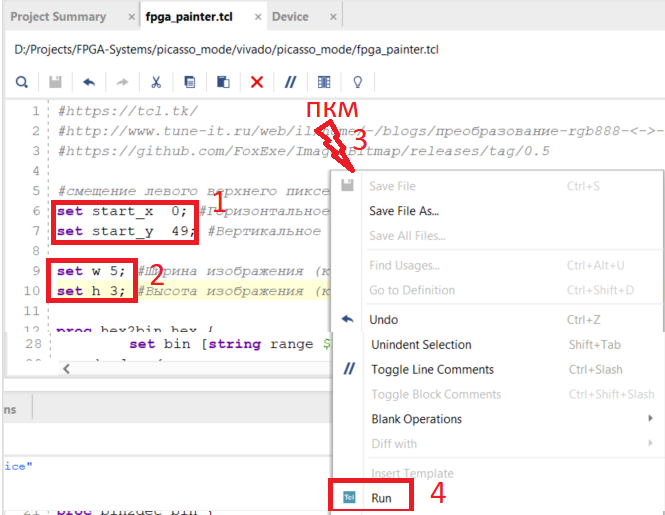
Let's open the script. Set the coordinate of the upper left pixel 0 and 49, the size of the test image is 5 by 3, and run the script. To do this, right-click in the script field and select Run.
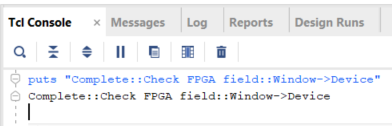
Go to Tcl console and make sure the script has been executed.
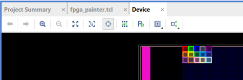
Go to the Device tab and make sure that the cells are colored in the appropriate color.
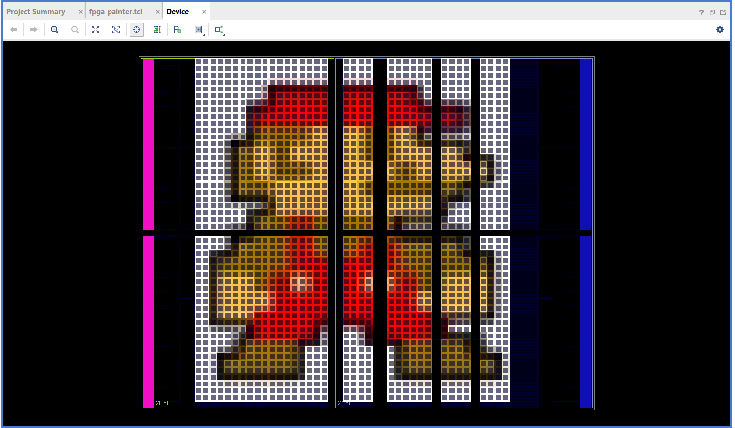
Now we can take any image, convert it to the desired size and fill in the FPGA field. Below are a few examples.
PS: custom color assignment replaces Vivado's default color setting
List of references
- UG835. Vivado Design Suite TclCommand Reference Guide
- https://github.com/FoxExe/Image2Bitmap/releases/tag/0.5
- https://tcl.tk
- http://www.tune-it.ru/web/il/home/-/blogs/conversion-rgb888 - <-> -rgb565-and-protection-mushrooms-from-fading