
I continue the series of three articles about the cloud smart home.
In a previous article , equipment for sensing a smart home was considered, as well as algorithms for converting sensory data into control commands for executive devices. The main component of a smart home is a controller, which most of the time works autonomously in accordance with the logic laid down at the setup stage. Various devices (IP cameras, sensors, actuators) are connected to the controller, which sends the data received from these devices to the cloud.
Now let's talk about the architecture of a cloud service for storing and processing information from sensors and cameras.
Cloud Service Benefits
A smart home cloud service offers a simple, flexible and inexpensive way to store and access data received from smart home devices. The user of the cloud service does not need to worry about the safety of their data. The capabilities of a multiprocessor media server, equipped with a disk basket with a RAID array of several 10 - 12 TB drives, far exceed the capacity of an SD or Flash card inside a smart home controller. In addition, memory cards are unreliable, as they have a limited number of rewriting cycles and often fail. The depth of data storage in the cloud is determined by the user's tariff and is easily configured in his personal account.
In addition, to access the data there is no need for “port forwarding” on the user's router when smart home devices are hidden from external networks by the NAT protocol. In your personal account, accessible from mobile devices, you can easily configure the configuration and logic of the smart home.
It is convenient not only to store data in the cloud, but also to process it, providing the user with statistics for various periods of time. Below we will consider an example of calculating the average room temperature per week based on multisensor measurements.
Cloud Service Architecture
In a previous article, we talked about a smart home controller that is installed on the user side and interacts with a cloud service using several protocols:
- MQTT is used to exchange JSON messages between the controller and the business logic server;
- HTTP to obtain the IP address of the least loaded media server from the load balancer of the cluster of media servers;
- RTMP to transmit the H.264 + AAC stream to the media server.
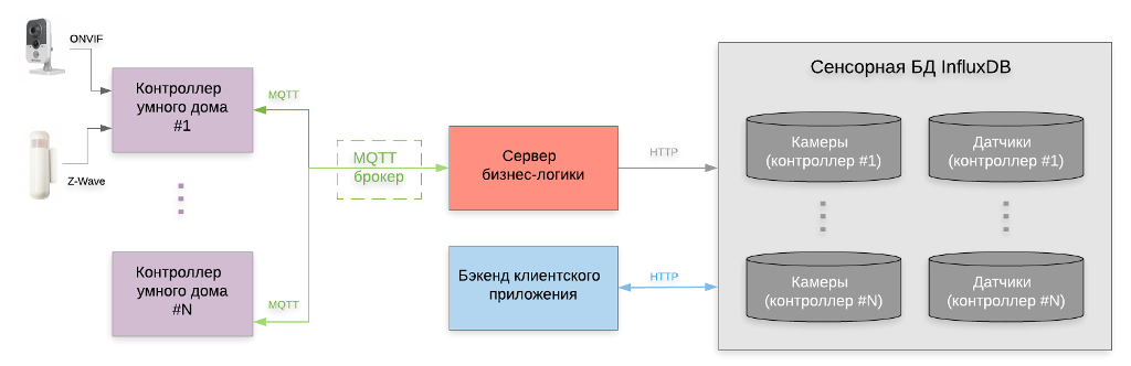
Now consider the cloud service of a smart home - the main components of which it consists, and how the interaction with the smart home controller occurs.
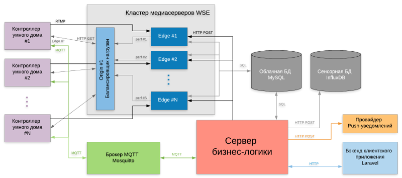
(click on the picture to open in higher resolution)
The business logic server is a key element in the entire scheme of information exchange within the cloud service. Its main purpose is to manage various server subsystems through RESTful API interfaces. It implements the logic of the cloud service based on the user model : recording a video archive and sensor measurements depending on the selected tariff, interaction between the user and the smart home controller, etc.
The MQTT broker is necessary for exchanging JSON messages between smart home controllers installed on the client side and the business logic server. Clients subscribe to topics within the broker that serve as message channels. As an MQTT broker, Eclipse Mosquitto is used .
A media server cluster is a distributed system for storing, processing, searching and playing video information for IP cameras of a cloudy smart home. A special load balancer collects information about the current performance of each server in the cluster, calculates the least loaded and reports its IP address to the smart home controller, which transfers video from cameras to it.
A cloud database is needed to store the user model of the cloud service, the configuration and current status of its equipment, as well as meta-information about the video archive entries. The MySQL DBMS is used as the implementation of the cloud database.
Touch Database is a non-relational NoSQL database. It stores events and measurements of smart home sensors, ordered by time. The use of InfluxDB DBMS, optimized for working with this type of data, significantly improves the performance of the cloud service.
The backend of the client application is a server application whose main function is to provide data received from the cloud and touch database in a convenient format for subsequent display by the client application on the user's device. The backend also generates control commands in JSON format for the smart home controller. The backend is based on the Laravel PHP framework. It will be discussed in more detail in the next article on a client application for interacting with a cloud smart home.
The push notification provider delivers messages about the events of the smart home to the user's mobile device so that he can quickly intervene in the situation (for example, when a water leak or smoke appears, call the appropriate response services). OneSignal service was chosen as the provider of Push-notifications, which has a convenient RESTful API interface and the function of identifying mobile devices necessary for the correct operation of notifications inside the user's personal account.
Business logic server
As mentioned earlier, the business logic server is a key component of the cloud smart home. Based on the user model (informational description of the system user, which includes system, personal, financial and logical features), he manages a variety of services within the cloud that have different implementations and functionalities and communicate with each other through RESTful API interfaces.

The business logic module inside the server is responsible for the following operations:
- management of storage of measurements of sensors and events of motion detectors from IP cameras of a smart home inside a touch database;
- managing the recording of the media stream of the IP camera broadcast by the smart home controller in the archive of the media server (constant / by motion detector);
- translation of commands from the client application to the smart home controller;
- broadcast the configuration of the smart home controller (connected devices, production logic rules defined by the user);
- sending push notifications about the status of the smart home controller and connected devices to the client application.
A feature of the business logic server is interprocess communication with remote applications running on multiple servers on the Internet. Most of the time, the business logic server application is idle on I / O locks, so it is designed based on a multi-threaded architecture and consists of a set of finite subtasks.
To ensure maximum efficiency, the internal implementation of the business logic server should be the simplest ( KISS principle ). Since the user model is completely deterministic and does not contain changing relationships between attributes, there is no need for a flexible inference mechanism (as in a smart home controller, where the user logic is configured by the user). Therefore, the operation of the business logic module inside the server can be described by a conventional algorithmic block diagram with conditional transitions.
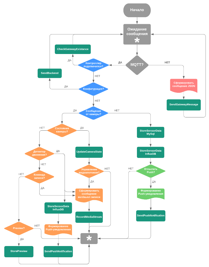
(click on the picture to open in higher resolution)
Immediately after starting up, the business logic server goes into the waiting state for messages using the MQTT protocols (from smart home controllers) and HTTP (from the backend of the client application). In case the message arrives via HTTP, this means that the user interacts with the client application and sends commands to the smart home controller or updates its configuration. In order for the message from the client to fall into the smart home controller, it is transmitted by the business logic server to the corresponding topic of the MQTT broker, to which the controller is subscribed ( SendGatewayMessage subtask).
At the initialization stage, the smart home controller waits for the user to register it in your account. Therefore, the sub-task CheckGatewayExistance is performed , which checks the corresponding status in the MySQL cloud database. To register in the personal account, the controller sends its full configuration to the business logic server, and that, in turn, broadcasts its backend to the client application ( SendBackend sub- task ), which creates and updates configuration records in the cloud and touch databases.
When the smart home controller is successfully registered in the user's personal account, the business logic server loads the user model from the cloud database into its RAM and starts processing messages from IP cameras and Z-Wave sensors in accordance with the following business logic algorithm.
JSON message from Z-Wave sensor with information fields:
{ "vendor": "*****", "version": "3.0.0", "timestampMs": "1571754749561", "clientType": "gateway", "deviceId": "c8e8de37-d301-45f4-ba01-************", "deviceType": "sensor", "protocol": "zwave", "messageType": "sensorData", "homeId": "0xefa0cfa7", "nodeId": "19", "sensorType": "SENSOR MULTILEVEL", "label": "Temperature", "sensorData": "26.1", "units": "C", "gatewayId": "6774f85a-0a5b-4059-9b68-************" }
When a message from the Z-Wave sensor arrives via the MQTT protocol, the following subtasks are performed:
- StoreSensorDataMySQL updates (UPDATE) an existing entry in the MySQL cloud database, where information about the current state and measurements from the sensor is stored. This is necessary for a client application that displays the current state of the smart home for the user;
- StoreSensorDataInfluxDB adds (INSERT) a new record to the InfluxDB touch database, where the history of measurements from the sensor is stored. This information is used in the calculation of statistical data for various periods of time (for example, energy consumption per day, month or year) and displayed in the client application in the form of graphs and tables;
- SendPushNotification generates a JSON message containing a time stamp, a sensor name, a text description of the event, the identifier of the smartphone of the user with whom he logged in to his personal account, and the internal identifier of the application in the OneSignal provider system. Further, this message is sent to the push notification provider through the RESTful API https://onesignal.com/api/v1/notifications , which delivers it to the user's smartphone.
An example of a JSON message from an IP camera with information fields:
{ "vendor": "*****", "version": "3.0.0", "timestampMs": "1571753150317", "clientType": "gateway", "deviceId": "1616453d-30cd-44b7-9bf0-************", "deviceType": "camera", "protocol": "onvif", "messageType": "deviceState", "deviceState": "streamingOn", "mediaserverIp": "***.***.***.***", "applicationName": "rtp-live-iot", "gatewayId": "6774f85a-0a5b-4059-9b68-************" }
When a message arrives from the IP camera using the MQTT protocol, the business logic server extracts its type from the messageType field. Depending on the value of this field, the following actions are performed:
- "MessageType": "deviceState" - the message contains information about the status change of the IP camera. The subtask UpdateCameraState is executed , updating information in the cloud database. If the deviceState field is either streamingOn or streamingOff (the IP camera sends / stops the data stream to the media server), the RecordMediaStream sub-task is executed , which generates a command to enable / disable the archive recording mode and sends it to the media server;
- "MessageType": "sensorData" - information about the operation of the motion detector on the IP camera. If in the user model the archive recording mode is set to “by motion detector”, then the RecordMediaStream subtask is executed . Next, the subtasks StoreSensorDataInfluxDB (saving the history of the detector in the touch database) and SendPushNotification (sending push notifications through the provider) are performed;
- "MessageType": "preview" - the message contains a frame of a thumbnail image from the IP camera, which is periodically sent to the cloud. The subtask StorePreview stores it in a cloud database. Further, it is used in the client application when displaying a list of cameras;
- "MessageType": "command" - a command sent by the smart home controller when the user changes its settings via the Web interface. The sub-task RecordMediaStream is performed , which, depending on the user model, turns on / off the recording mode on the media server.

(click on the picture to open in higher resolution)
As a result of the work of the business logic module, a task queue is formed - a sequence of minimal sections of code that are executed independently of each other. The task queue is passed to the thread pool , which distributes the tasks among the free cores of the central processor. When an I / O lock occurs during execution, the thread pauses and enters the idle state and frees the core of the central processor, which allows the thread pool to start the immediate execution of the next task from the queue. At the moment when the I / O lock is released, the blocked thread changes its state to working and continues execution as soon as one of the cores of the central processor is freed.
Thus, by decomposing the business logic task into many separate sub-tasks that are executed simultaneously, the performance of the business logic server is increased. System scaling is achieved by increasing the number of cores of the central processor and increasing the number of business logic servers in the system.
The business logic server application is developed in C ++ and runs as a systemd service of the Linux operating system Debian Sarge. For additional performance monitoring, the monit resource monitoring system is used, which restarts the service in case of performance problems.
Currently, the cloud service runs one business logic server running on the Yandex. Cloud virtual machine. Virtual machine parameters - 4 vCPU cores with a guaranteed share of 20%, 2 GB RAM, 100 GB HDD. According to the calculations, this performance is enough to process messages from ~ 1000 smart home controllers with 3 IP cameras and 5 Z-Wave sensors each (the calculations will be updated during the operation of the system).
Media server
A media server is a dedicated server on which special software is installed for:
- receiving streams of video and audio data from encoder devices using specialized network protocols;
- storing data in the form of archive files in its file system;
- Broadcast information from archive files in a standard streaming format for playback on client devices.
The Wowza Streaming Engine 4.7.2 with additional modules developed in the Java language is used as a media server in the cloud smart home system for recording streaming data to a file archive and for working with a cloud database.
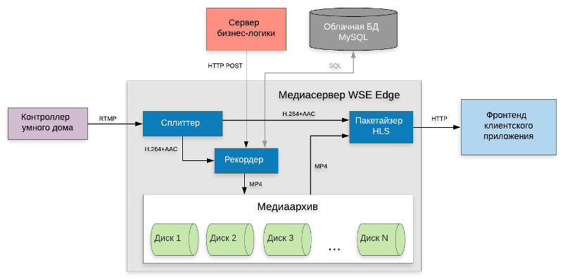
(click on the picture to open in higher resolution)
The media stream from the smart home controller in RTMP format enters the media server and is aligned with time stamps in the jitter buffer . This is necessary to compensate for the effect of network packet delays when transmitting data flow over the Internet.
To record the video stream to the media server file system as an MP4 file, the business logic server sends the following command to the media server through the RESTful HTTP API:
http://<mediaserverIp>:<port>/v2/servers/_defaultServer_/vhosts/_defaultVHost_/applications/rtp-live-iot/instances/_definst_/streamrecorders/1616453d-30cd-44b7-9bf0-************ { "instanceName": "_definst_", "fileVersionDelegateName": "CustomFileVersionDelegate", "serverName": "", "recorderName": "1616453d-30cd-44b7-9bf0-************", "segmentSchedule": "", "outputPath": "", "currentFile": "", "applicationName": "rtp-live-iot", "fileTemplate": "", "segmentationType": "SegmentByDuration", "fileFormat": "MP4", "recorderState": "", "option": "", "currentSize": "0", "segmentSize": "0", "segmentDuration": "1800000", "backBufferTime": "0", "currentDuration": "0", "startOnKeyFrame": "true", "recordData": "false", "moveFirstVideoFrameToZero": "true", "defaultRecorder": "false", "splitOnTcDiscontinuity": "false" }
The name of the video stream (the IP camera identifier on the smart home controller) is indicated in the recorderName field, in the fileVersionDelegateName field - the name of the inherited class for determining the path to the folder and file name. The Java code for the class is shown in the following listing:
import java.io.File; import java.util.Calendar; import java.util.TimeZone; import com.wowza.wms.livestreamrecord.manager.IStreamRecorder; import com.wowza.wms.livestreamrecord.manager.IStreamRecorderFileVersionDelegate; import com.wowza.wms.logging.WMSLoggerFactory; public class CustomFileVersionDelegate implements IStreamRecorderFileVersionDelegate { @Override public String getFilename(IStreamRecorder recorder) { String sDisk = GetDisk(); if(sDisk == null) { WMSLoggerFactory.getLogger(null).error("CustomFileVersionDelegate::getFilename(): No drive chosen"); return null; } String sStreamName = recorder.getStreamName(); int nCameraId = Integer.parseUnsignedInt(ServiceQueries.GetCameraId(sStreamName)); TimeZone tz = TimeZone.getTimeZone("Europe/Moscow"); Calendar now = Calendar.getInstance(tz); String sDirPath = ServerParams.m_sServerContentPath + "/" + sDisk + "/" + Integer.toString(nCameraId / 200) + "/" + sStreamName + "/" + String.format("%1$tY/%1$tm/%1$td", now); String sFullFilePath = sDirPath + "/" + sStreamName + "_" + String.format("%1$tH_%1$tM_%1$tS", now) + ".mp4"; File dirs = new File(sDirPath); dirs.setExecutable(true); dirs.setWritable(true); dirs.mkdirs(); WMSLoggerFactory.getLogger(null).info( "CustomFileVersionDelegate::getFilename(): Filename created: " + sFullFilePath); return sFullFilePath; } }
In the CustomFileVersionDelegate class, the virtual getFilename function of the base class IStreamRecorderFileVersionDelegate is overloaded , which is called by the media server before recording the stream to a file. The function creates a folder on disk with the path sDirPath and returns the full path to the sFullFilePath file.
Since the volume of media data is very large, the file system includes several physical disks of large volume (8 - 12 TB) mounted as subdirectories. The disc with the largest amount of free space is selected as the target disk during recording. For optimal operation of the file system when accessing the file, the path to the target folder is formed as follows:
/content/<diskId>/<cameraIdDivideBy200>/<streamUuid>/<year>/<month>/<day>/
where diskId is the identifier of the disk (mounted folder),
cameraIdDivideBy200 - the result of integer division of the camera identifier by 200,
streamUuid - media stream identifier,
year, month, day - year, month and day of recording, respectively.
This avoids a large number of subfolders within one folder and, accordingly, a dramatic drop in the performance of the entire file system with an increase in the number of IP cameras in cloudy smart homes.
Information about the IP address of the media server, the path to the file with media data, the start and end time of writing to the file is stored in the cloud database and then used by the client application to display the archive timeline on which the video can be selected and played.
To receive the video stream, the front-end of the client application accesses the media server by sending the following commands via HTTP. For a "live" video stream:
https://<mediaserverIp>:<port>/rtp-live-iot/<streamUuid>/playlist.m3u8
For archived video stream:
https://<mediaserverIp>:<port>/vod/_definst_/mp4:<diskId>/<cameraIdDivideBy200>/<streamUuid>/<year>/<month>/<day>/<fileName>/playlist.m3u8?wowzaplaystart=<offsetMs>&wowzaplayduration=<durationMs>
where fileName is the name of the archive file on disk,
offsetMs - playback offset relative to the beginning of the file in milliseconds,
durationMs - duration of playback in milliseconds.
The media server sends a stream in HLS format, which allows you to display H.264 + AAC video in all modern browsers and mobile devices with iOS and Android operating systems. The HLS packetizer encodes the stream in the form of separate chunks and sends it over HTTP as a response to a request from a mobile application.
To optimize storage costs and access to archive files, the cloud smart home media server is developed on the Supermicro CSE-825TQ hardware platform, motherboard X8DT6, 2xCPU Intel Xeon E5645 2.4 GHz, 32 GB RAM, 44 TB HDD Adaptec AAC-RAID. The media server is installed as a dedicated server on the hosting site and connects to the Internet channel with a guaranteed width of 400 Mbps. The performance of one media server is sufficient to process media streams from ~ 400 IP cameras with the H.264 codec, 720p frame resolution and 1 Mbps bitrate.
Accordingly, in order to be able to process streams from 1000 IP cameras, it is necessary to install 3 media servers and evenly distribute the load between them. For this, a load balancer is used, which is connected to the Wowza Streaming Engine media server as a separate Dynamic Load Balancing AddOn plugin. This distinguishes, in fact, the load balancer (or origin server ), which periodically receives the performance metrics from the final media servers (or edge servers ) and, based on this information, finds the least loaded server in the cluster.
The smart home controller accesses the balancer via HTTP and in response receives the IP address of this server, to which the controller transmits the media stream from the IP camera via RTMP. The performance metric includes the number of established connections with sources and consumers of media streams and the current bandwidth of the Internet channel on the server. In the settings of the balancer, you can also specify the choice of edge-server, taking into account its geospatial position, which allows you to host servers in different cities and countries to create a distributed network for delivering CDN content.
Touch database
As mentioned in a previous article, the readings of Z-Wave sensors, as well as the current status and events of IP cameras are sent in JSON format by the smart home controller to the cloud using the MQTT protocol. The business logic server decodes these messages and runs the StoreSensorDataInfluxDB subtask, which transmits data to the touch database via HTTP.
(click on the picture to open in higher resolution)
The cloud database of the smart home is developed on the basis of InfluxDB 1.7.x - an open source database management system for working with time sequences, which is used in many projects of the Internet of Things to store data from sensors and analytics. Queries to the touch database are generated in the InfluxQL language similar to traditional SQL.
The data storage time in the cloud smart home is determined by the selected tariff according to the user model. Due to the significant difference in the amount of video data and sensor data, their storage time will be different. The size of the video archive is measured in days (7, 14, 30 days at different rates), and the size of the archive of sensors is measured in years (3, 5, 7 years, respectively). Therefore, for each smart home controller, when it is registered in the user’s personal account, 2 separate databases with different retention policies are created inside the touch database:
CREATE DATABASE "gateway_6774f85a_0a5b_4059_9b68_************_cameras" WITH DURATION 720h SHARD DURATION 1h; CREATE DATABASE "gateway_6774f85a_0a5b_4059_9b68_************_sensors" WITH DURATION 61320h SHARD DURATION 24h;
The backend of the client application is responsible for creating, editing and deleting the database inside the touch database. For example, if a cloud smart home user changes the tariff, the backend sends the following commands to make changes to the storage policy:
ALTER RETENTION POLICY "autogen" ON "gateway_6774f85a_0a5b_4059_9b68_************_cameras" DURATION 168h SHARD DURATION 1h;
When removing the smart home controller from the user's personal account, the backend deletes the corresponding databases:
DROP DATABASE "gateway_6774f85a_0a5b_4059_9b68_************_cameras"; DROP DATABASE "gateway_6774f85a_0a5b_4059_9b68_************_sensors";
Upon receipt of an informational message from the smart home controller, the business logic server performs a request to insert data into the touch database:
INSERT device_20873eb0_dd5e_4213_a175_************,class=METER,label=Energy,units=kWh value_float=0.05 1572194550125;
An example of a table with data from Z-Wave sensors for one smart home controller:

One of the most useful features of a cloud house is the calculation of statistics based on the data received. The user needs to know the average temperature in the room or how much electricity he spent per month.
The InfluxQL language allows you to perform queries using analytic functions . For example, to calculate the average temperature for a week, you need to run the following query:
SELECT MEAN("value_float") FROM device_63c660da_f0e8_4eca_8d5f_************ WHERE label = 'Temperature' AND time >= '2019-10-21T00:00:00.000Z' AND time <= '2019-10-27T23:59:59.999Z' GROUP BY time(1d) fill(null);
The results of this query are shown in the table:
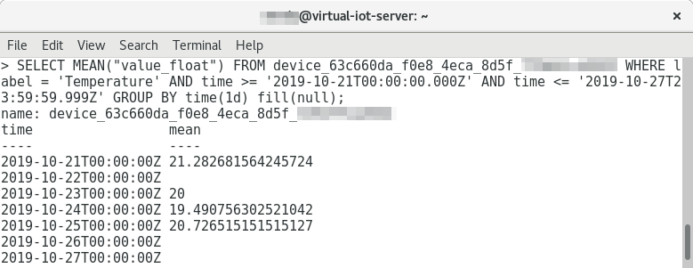
In the next article, which is entirely devoted to the client application, we will consider in detail the calculation of statistics for various parameters and the construction of tables and graphs based on it.
In the cloud smart home system, the InfluxDB DBMS is deployed on a Yandex. Cloud virtual machine with the following parameters: 4 vCPU cores with a guaranteed share of 20%, 2 GB RAM, 100 GB HDD. According to the calculations of this configuration, it is enough to store sensor data from 3,000 IP cameras and 5,000 Z-Wave sensors for 7 years.
Conclusion
The article examined the architecture of a cloud service for a smart home, the algorithm of a business logic server, the architecture of a media server for recording, storing and playing media streams from IP cameras, as well as the architecture of a touch database for storing and analyzing data from smart home sensors. The cloud service system works on both dedicated and virtual servers, for greater stability located on different hosting sites. The system is currently undergoing trial operation.
The older the data stored in the cloud, the less often the user accesses it. In the next version of the cloud service, it is proposed to use the mechanism of thinning (or oversampling) data using InfluxDB Continuous Queries in order to reduce the amount of stored data using aggregating functions and, thereby, increase the capacity of the touch database.
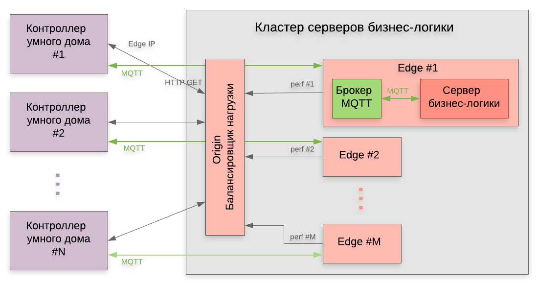
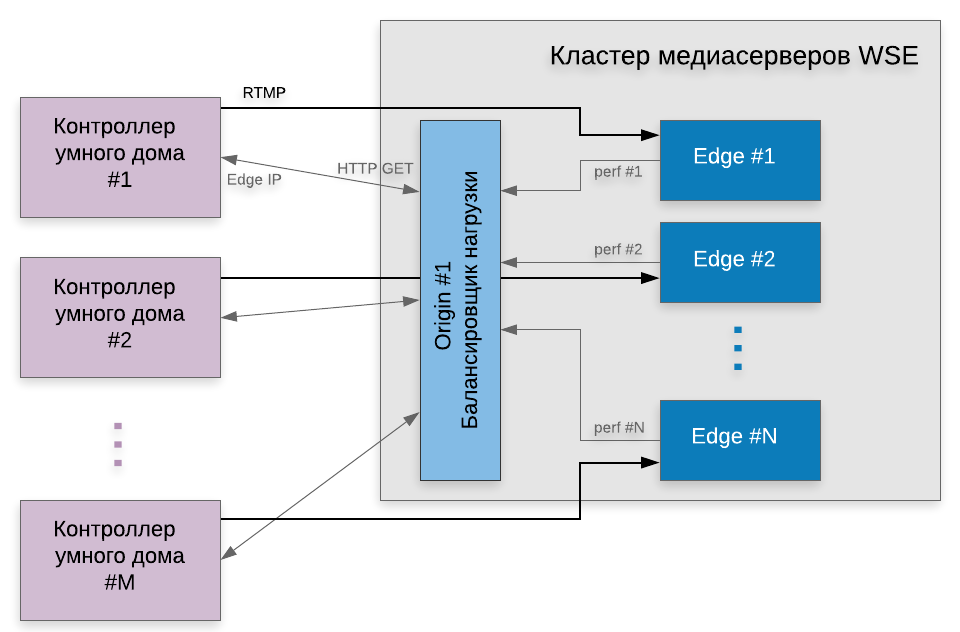
Also, in the next version of the cloud service, a cluster of business logic servers will be implemented according to the principle of a cluster of media servers, discussed in this article. The figure shows the architecture of such a cluster, where several edge servers (each of which has a separate MQTT broker and business logic server software) send performance metrics to the origin server, which calculates the IP address of the least loaded server. This will allow you to scale the system to a greater extent and overcome the existing limit of 1000 smart homes.