
The theme of the story is at the junction of hardware and software aspects. And in the firmware for the controller, I was not dealing with some abstract concepts or data, but with very real "physical" devices: relays, electric motors, transistors, etc. So I will give a brief description of the technical part, the composition that was at the time of all the dances with a tambourine.
Main nodes
Traction motor - universal collector. It can work both from direct and from alternating current. Operating voltage 220 volts.

Battery - 25 lead-acid cells of 6 volts from Casil each connected in series; as a result, we get a battery of 150-160 volts. It is installed at the back and rewound with blue electrical tape, everything is as it should :)

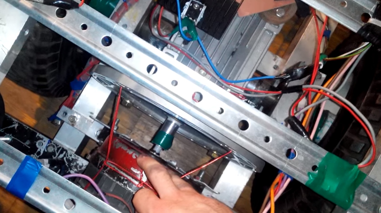
The engine drives the wheels through a worm gear with a gear ratio i = 10. The photo shows that the engine is coupled to the gearbox using a small roller, it was specially machined.
The braking system, that is, the brake disc with the caliper was not in principle. Put a physical brake at that time did not work. Therefore, engine braking remained the only real option, so the controller also had to take control of the braking of the machine.
Controller for control unit
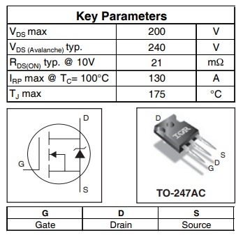
In principle, a simple controller for an electric car can also be assembled on a “loose bed”. But I would like it to be able to beautifully configure everything with the help of the program, after all, the 21st century. After much highly scientific discussion at dinner, I decided that the controller should be based on the Microchip chip - pic16f877a, here are its brief characteristics:

At that time, I did not really fumble in electronics, and initially I wanted to make the circuit stupidly disgraceful - the engine is turned on or the engine is turned off, but instead of a relay put a transistor key so that nothing clicks and does not burn. But I decided that the risk was justified, I did not lose anything and I just wanted to do something worthwhile. So I settled on a bunch of microcontroller + power field-effect transistor as a key. The throttle and reverse button brought to the steering wheel.
Circuit features
When choosing a transistor, I did not skimp and chose IRFP4227PBF - an N-channel field-effect transistor (opens with a positive pulse) for a voltage of 200 volts and a maximum current of 130 amperes. Case TO-247AC. But, looking ahead, I’ll say - I was able to burn it.
PWM - what is it and what does it eat with
Since I used a microcontroller in conjunction with a field-effect transistor, it was a sin not to try using pwm / pWM in the circuit. What is a shim? Pulse Width Modulation (PWM) is a process of power control using the pulsed on and off method. - thanks to Wikipedia.
The advantage of this method of controlling the transistor: during operation, it is in two states - either completely closed, there is no current and nothing is warming up, or it is completely open and its resistance is several miles, respectively, some fractions of a watt of heat are dissipated into the heat on the transistor itself , or units of watts, the circuit is barely warm in this mode of operation. And such a process - open / close occurs thousands of times per second. This is called the PWM frequency. There is also such a thing called “duty cycle”. Translating into human language - this figure shows how much time the transistor is open. If you go a little deeper, let's say we have a frequency of a PWM signal of 1000 hertz. So the transistor opens and closes 1000 times per second, and the switching process between on and off is 1/1000 a fraction of a second. The value 1/1000 is the period of the frequency. And with the help of the duty cycle, we show what part of the time from the period the transistor is open and current flows through it. For example: in the program, the duty cycle 255 is the maximum power, 127 - 50%, 0 - the transistor is closed.
To generate such a frequency, the “physical” controller built into the chip was used, although there is a possibility of software implementation, but in this case the controller will only do what to generate a frequency with a given period and duty cycle on the output. And using a controler from the periphery of the MK, it was possible to generate a signal, and so that the program would do something else.
The farther into the forest, the angrier the wolves - how effective the electric drive will work depends on the frequency of the PWM. I tried different frequencies, from 2 to 15 kilohertz, each time it changed programmatically. Honestly, I didn’t manage to notice much difference, but I’m sure that it is. Unfortunately, data on this issue could not be obtained in sufficient quantities. The only thing I noticed was that the machine squeaked at different frequencies during operation. By the way, if someone noticed in the subway, electric buses and trains that during the start you can hear a rumble, a squeak, howl - this is just the same squeaking of the motor windings due to operation at the controller frequencies. This is very noticeable on the train "Swallow", which goes along the MCC during the start.
Pitfalls in the algorithm of work
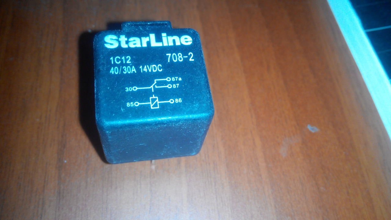
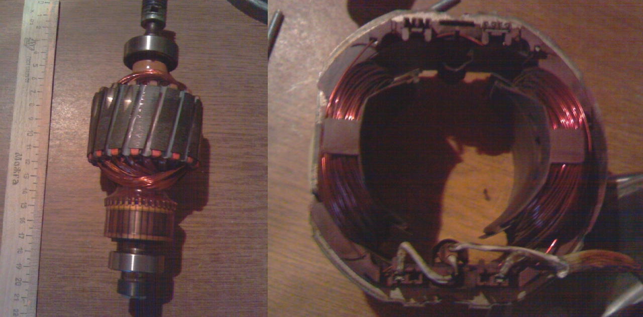
The next problem was with engine reverse. The engine is collector, it has two windings - fixed - stator, on the body, and rotating - rotor. To change the direction of rotation, it is necessary to deploy the direction of the current in one of the windings, not me the direction in the other. For this, two relays were used, they worked simultaneously, "throwing" the circuit to reverse when power was supplied to them. But in the first version of the firmware there was an error - the relays switched under load. As a result of the test under load, there are two burned-out relays, since the motor is an inductive load and there was a strong arc on the relay contacts, the contacts simply melted and burned during switching.
The way out of the situation is to introduce into the program the condition that before switching off we remove the load by unscrewing the duty cycle of the PWM signal by 0, throw the relay, and again turn on the power to the specified level. This is exactly how the brakes on the car worked - reverse. Only hardcore - no sensors and encoders, nothing. And here’s the photo of the relay, it’s kind of like a starter relay from the Lada. If you switch them under no load, then they also work with high voltages, they kept 160 volts at 15 amperes, but I assume that the contacts were heated due to the small cross-section.
After I finished the firmware, and the power rose smoothly to a given level. And this already eliminates shock in the transmission and load on the nodes. This is how one line in the program can increase the life of the unit.
We connect the controller with the transistor correctly
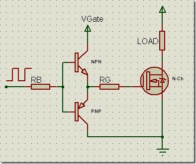
It only remained to correctly connect the transistor with the controller. I did this somewhat incorrectly, through an optical pair, directly. But this circuit rolls when working with low voltages, at high operating voltages the shutter of the transistor constantly burns, and a push-pull driver is needed for control. The normal circuit is shown below. Nevertheless, at one time, the circuit with the optical pair was enough, by some miracle, it worked for a test drive, and it started to burn out immediately after it. Here is the diagram of the “correct” driver, only in my version there was still a decoupling of optics from the controller. Image taken from Drive2:
Some interesting points
- When starting, the electric motor consumes many times more electricity even without load. And when the rotor braked during the start, the graphite brushes began to smoke.
- At that moment, when the transistor burns out on the machine - it starts to go by itself, because only the transistor separates the battery from the engine. So the introduction of protection schemes is justified if you do not want to run after the car and pray that it will not hit anyone.
- The engine I used is from a washing machine. Turnover without load, he claimed 14,000 - it is hard to believe, but this number was on the nameplate. Although he pulls perfectly "from the bottom."
- The voltage on the battery sags, without load I had about 150 volts, it can calmly be 140 under load. And if the battery is too low, then 130, because of this, the car could drive very well on fresh batteries for the first few minutes, then when the batteries spent somewhere around 20-30% of the energy, a more or less working mode began, the car drove more slowly, accelerated more slowly, but it was not so noticeable. When the batteries consumed approximately 70% of the charge, the ride turned into a turtle course.
- I even managed to burn a rather powerful transistor due to overvoltage on its shutter. To protect against this, you need to shunt the transistor gate with a diode to the + power supply of the transistor driver.
- The relays were connected to the MK using low-power transistor switches on small voles.
In the end, what happened on the video
In general, my experiments with the electric drive started back in school and I tried many different designs, but this is the most successful scheme at that time. If you like the material, I’ll write a separate post about the whole epic.
UPD: Changed the errors in the article, thanks to everyone who responded