Where do the “legs” grow from
Nowadays, various programmed machines have become available and have gained popularity. These are laser and milling cutters and engravers. As well as 3D printers. All these machines have one common node - a stepper motor.
And this engine needs a driver.
The principle of engine operation is not the subject of this article. We will consider only the driver. All we need to know in this context is what control signals we need to generate to control the stepper motor. It turns out that these are the most common rectangular pulses.
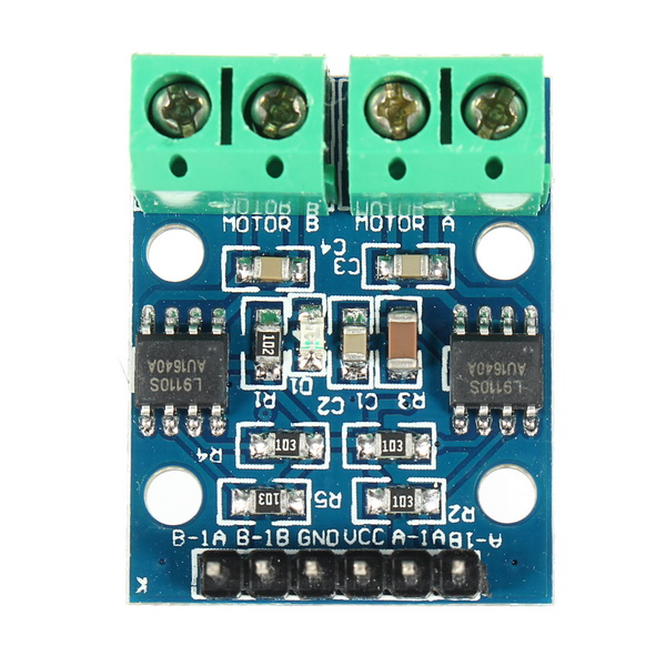
There are a number of driver solutions from various companies. In our article, we will consider the most affordable solution for the L9110 driver and its analog HG7881. This solution is often used in Arduino
Theory and practice
I decided to use the L9110 chip in my project.
Quite easily googled datasheet . Read. Everything is very clear. Characteristics, pinout, truth table ... In all respects, the driver seems to be suitable. The switching voltage is 12 volts, the output current is 800 mA. - just enough.
And what really is?
Without delay in the "long box" I made a board, wrote and launched a test program ...
The first thing I noticed in my device is that the driver chip is very hot. Attention! Idling. Without load. What are these miracles of circuitry?
Maybe my chip is defective?
The idea came up to consider this device in more detail. And not one, but a bunch.
No sooner said than done.
It’s good that I had an in-stock SO-8 socket and a simulation board.
Well, and a controller based on STM32.
The stand was assembled and measurements were made.

Yes, by the way, in addition to directly, the power node in the chip embedded logic exclusive OR. In a datasheet it is described .
Since I am studying the effect of heating the microcircuit, it is better not to limit myself to logical ones and zeros, but to remove real voltages.
As a result of the measurements, a plate was obtained:

Consider lines 2 and 3. What do we see here?
- The voltage drop at the output transistors, when there is a load, is about one and a half volts, which at a current of 0.33 amperes gives 0.5 watts per channel.
- At idle, the microcircuit consumes 0.05 A, which at a voltage of 12 V gives 0.6 watts per channel.
In other words, regardless of the load, it consumes about 0.5 watts per channel. Now it’s clear why I burned my fingers about her.
Strong heating is, of course, a drawback. But maybe the chip performs its function well? Here, a recently-attached 4-ray prefix oscilloscope came in handy. I did not expect me to need all 4 beams so soon. For testing, I wrote a simple program on stm32, which I have been using for a long time in various projects. The program simply generates 2 rectangular signals with a three-fold frequency difference.
Since it is better to see once than to read many times, I apply a scan of the control signals.

Nothing too complicated. Just rectangular pulses shifted with a frequency difference of 3 times.
The upper part of the screen - input signals - the lower - output.
It is immediately evident that with varying values of the signals at the inputs, the values at the outputs are quite clear. They are set without delay and with sharp edges.
If the signals at the inputs coincide, then the front is gentle. similar to capacitor discharge.
Looking through the documentation, I did not see anything that portended such behavior.
Maybe I set the input frequency too high? There is no limit in the datasheet.
Already knowing that this driver has an almost 100% analogue of the HG7881, I turned to its documentation .
She shed more light on this mysterious situation. It turns out that the logic of the driver is a bit wider. Two units at the input are braking (that is, at the output both signals must be low.) And two zeros at the input are “hanging” contacts. The gap.
So two zeros at the input should “suspend” the outputs. Then, the behavior of the discharge capacitor is quite predictable. However, two units at the inputs - should be a reliable zero at the output. But in fact this is not so.
I could blame this defect on the "Chinese manufacturer." However, I tested the chip honestly soldered from the Arduino board. At what - not one chip. From several boards. That is, the probability of marriage is greatly reduced.
Output
The scope of the L9110 microcircuit is narrower than declared, and the efficiency is low.
The scattering of 0.5-0.6 watts on one key is a bit too much. It is no coincidence that this solution is the cheapest. (10 cents per chip. On aliexpress).
The following articles will discuss alternative stepper motor drivers.