Why did I need this?
In short: I wanted to expand my CNC machine, but something went wrong ...
Full story
Since childhood, I wanted to have my own CNC machine, because dealt with models of aircraft where you need to make a lot of small repeating details. First I bought a ready-made DIY kit , and then I decided to increase it. I played for two months, but still the machine is small, the working area was only 18 by 10 cm, it does not have positioning sensors. I decided to buy a larger guide, put the limit switches and install the carriage in the middle with a stepper motor. I did it in half a day, but you can’t go straight to the dream - to a large CNC, you need to complicate the task and put the pendulum on the carriage, then it seemed easy to me, but I had to remember the institute years and get acquainted with TAU.
Unsuccessful attempts
The project took almost two years of trial and error, redesigning, waiting for details and incomplete days off so that those who wish to repeat saved their time and nerves, I consider it necessary to talk about unsuccessful decisions.
- a gyroscope (MPU6050) instead of an encoder - fundamentally nothing against it, but the sensor should be located on a rotating rod, this introduces an unpredictable effect and the inability to scroll the rod several times around the axis.
- absolute encoder - if it is a potentiometer, then even the movement of wires (mainly due to contacts in the arduino) introduces noise into the measurements, a 10-bit ADC is still not enough; if it is a more expensive sensor, then reading takes place via a serial interface, and this introduces a delay in the system, especially in combination with a stepper motor.
- the rigidity of the system - at some point I took an aluminum tube with a load at the end, with vibrations of the carriage, strong vibrations started in it, and it was not immediately clear which system we were stabilizing. We must strive to ensure that the physical system is as close as possible to what is modeled.
- friction - this phenomenon is often neglected, I tried to reduce it using large carriage wheels and V-slot profiles, in contrast to rails with sliders with small balls, because rolling friction is inversely proportional to the radius.
- the use of a stepper motor - I spent a lot of time trying to go this route, it is misleading to simplify the formulas (in fact, we immediately control the acceleration of the base of the pendulum) and the simplicity of the design (we can forget about the friction in the rail, the motor encoder, if we assume that the motor does not skip steps) but ... To accurately control the speed, the time between steps should be tens of microseconds, so you can forget about the state output to the console. Without feedback, you cannot be sure that the motor has not missed the steps and the speed is really the way the system thinks. I do not claim that this is a dead end solution, if someone succeeds in stabilizing the pendulum with a stepper motor, I will be glad to look at it.
Free pendulum
To complete the picture, we simulate a pendulum on a free carriage without friction.
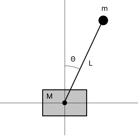
The equations of motion can be obtained by differentiating the Lagrangian with respect to generalized coordinates. We obtain the following equations:
from which you can find how the state vector changes:
and simulate the system. The code is here .
Why is the system unstable?
Common sense and visualization tell us that the pendulum itself will not stand. But how to verify this mathematically?
In general terms, the linearized system and solution are as follows:
An exponent in the power of the matrix looks clearer if you go to the coordinate system from eigenvectors, then the matrix will be diagonal ( ), and the exhibitor will look like:
Now it is seen, in the presence of eigenvalues ( ) with a positive real part, the corresponding component of the state vector will tend to infinity, and the system will fall apart. The above applies to continuous systems, more about sustainability is described in this video lecture.
Check if this is the case for the reverse pendulum. We linearize our system near the equilibrium position for :
Nonzero eigenvalues have the form , thus we became convinced of instability.
Add feedback
Now the force will act on the carriage , one of the equations can be rewritten in the form: , and the linearized system will take the form:
Now the system ( ) became controllable , this can be verified by checking that the rank of the matrix equal to the dimension of the state vector, i.e. 4. To keep the pendulum in an upright position, I used a linear-quadratic state controller, ie control (u or f) is the product of the state vector by a vector of parameters that are found once by minimizing the quadratic functional . The simulation code is here .

Engine control
Now you need to control the DC motor, it contains many parameters that I do not know, so I took it for a "black box", described by the following equations, taking into account friction:
You can read about the derivation of equations and parameter estimation here . Below are my graphs of the acceleration of the motor with the carriage depending on the voltage (in reality, the PWM signal is output from the controller) and the fitted curves.

I also found the coefficients of the model by brute force, the code .
Thus, the controller gives us the required acceleration, and from the 2nd equation, knowing all the constants, we find the voltage.
Putting the real device together
Now we have all the knowledge to collect and stabilize the pendulum. I used the following iron:
- Arduino Mega 2560 is not UNO, because two encoders need 4 pins for interrupts
- The encoder for the pendulum - OMRON E6B2-CWZ6C 2500 pulses per revolution - gives us the angle, we calculate the angular velocity, the resolution is quite high, so there were enough finite differences without smoothing and averaging
- Encoder for the motor - LPD3806-600BM-G5-24C 600 pulses per revolution - gives the position of the carriage, calculate the speed
- 12V DC motor with 5: 1 gearbox
- 10Amp 5V-30V Motor Driver
Thus, we explicitly measure the angle of the pendulum, the position of the carriage, calculate the angular velocity of the pendulum and the speed of the carriage - we get the full state, I found the controller parameters with this script. To my surprise, everything worked pretty quickly as it is. I am satisfied with the result, it stands and even holds a glass!
The code for Arduino is here
What could be improved compared to many of the options that can be found on youtube - this pendulum is quiet because the PWM is tuned outside the auditory range and plastic wheels are used.
Now this task looks like a laboratory work: measure the parameters of the motor and find the coefficients of the regulator, simultaneously understanding what is happening.
What's next?
I plan to produce a pendulum: make a swing, get rid of a coil of wires, make a shield with convenient connectors, so as not to be ashamed to present to some school or museum. If someone wants to join, I will be glad there are many more ambitious ideas.
References
- Detailed description of the inverse pendulum problem
- We chew a linear-quadratic regulator to control an inverted pendulum - this article saved me a lot of time when building my pendulum
- Excellent video lectures on TAU
Thanks for attention!