- Hello everyone, my name is Vitaly Podkolzin, I’m the head of the development of embedded systems for the unmanned vehicle project. And today I would like to talk with you about what an unmanned car is, what components are included in its composition, how to make the car move and how the autopilot and its components work depend on the devices used.
To understand where to go next, a person first needs to find out where he is. An unmanned car too. For this, the localization subsystem is responsible for us. Then you need to understand what is happening around us. The system of perception or perception is responsible for our vision, perception of the world. Based on location data, about objects around us, we can make forecasts on the road situation, on its development, on the behavior of road users. And choose the optimal route of movement, trajectory, further turning it into a control action.
But all of the above are, in the general case, algorithms. And you could run these algorithms on your computer, if it were powerful enough. Of course, this would not make an unmanned car out of a computer. Two important things are missing.
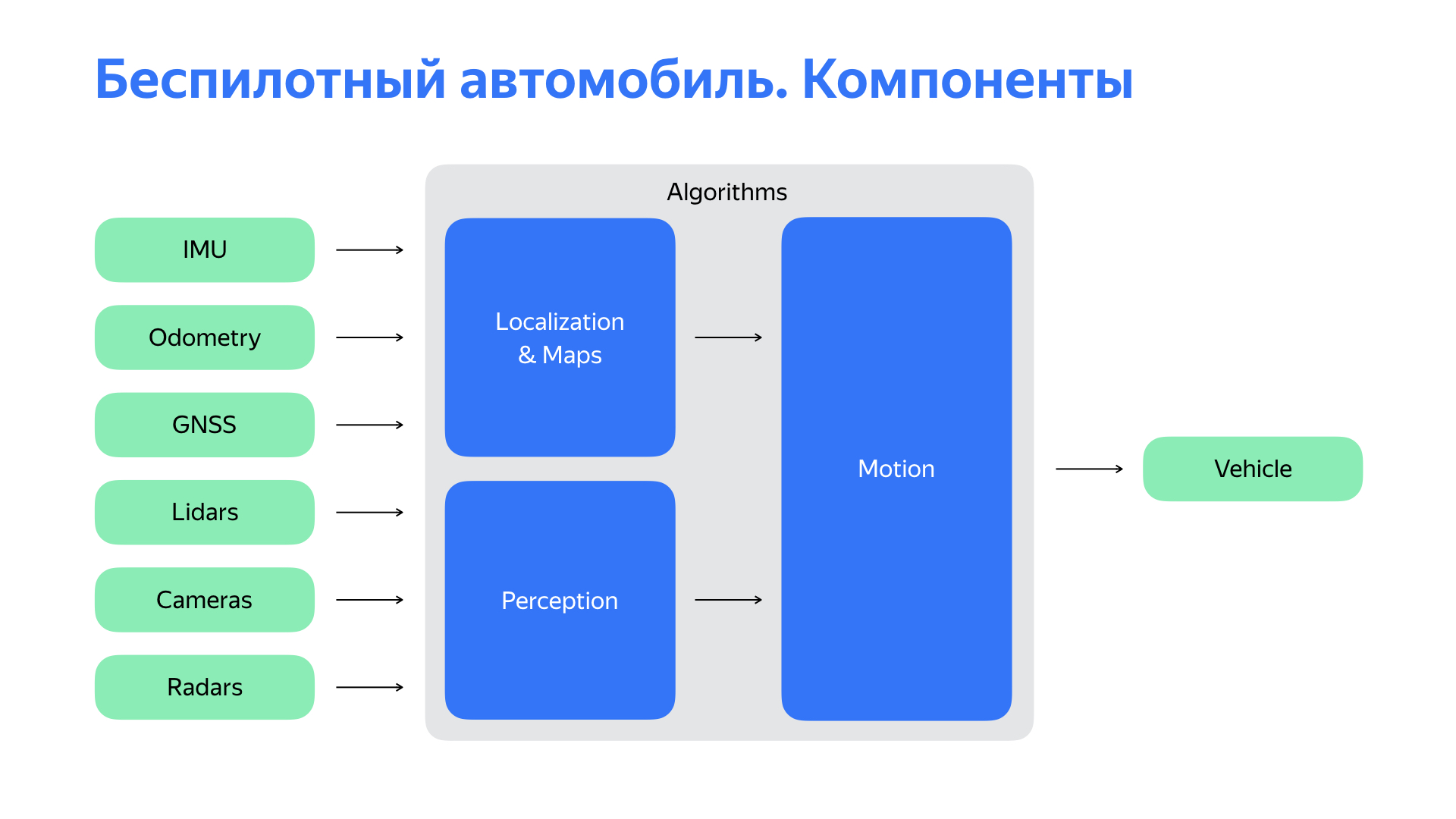
The first is a fairly rich set of sensors, the main of which are listed on the slide. And of course, we need a platform that will execute our commands. You need to interact with her.
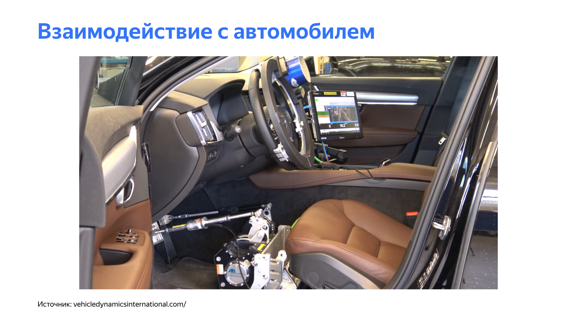
Let's dwell on the issue of interaction with the car. Autopilot, like a person, needs to do simple things to drive a car: turn the wheel, accelerate, slow down. A logical solution may seem to use actuators to control these bodies.
Link from the slide
But this approach has a number of significant difficulties. The development of an unmanned vehicle still implies the presence of a driver at certain stages - you need to take the car to a service or monitor the autopilot when we test various features, especially in the early stages. These devices significantly complicate the life of the driver.
Of course, the whole system is complex, and in general such mechanics can introduce unpleasant delays in the controls. This negatively affects the vehicle control circuit.
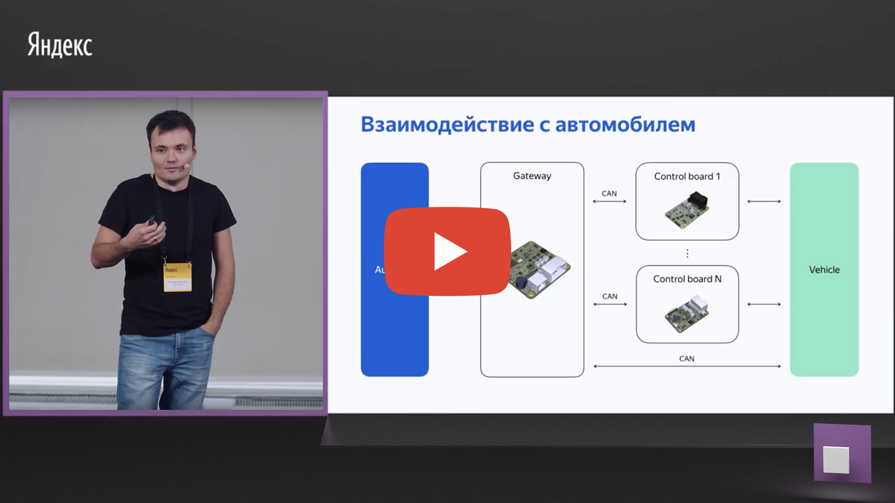
Yes, we still needed a simple platform at the start of the project, but we needed some other approach to interact with this platform. And we started digging deep into the car.
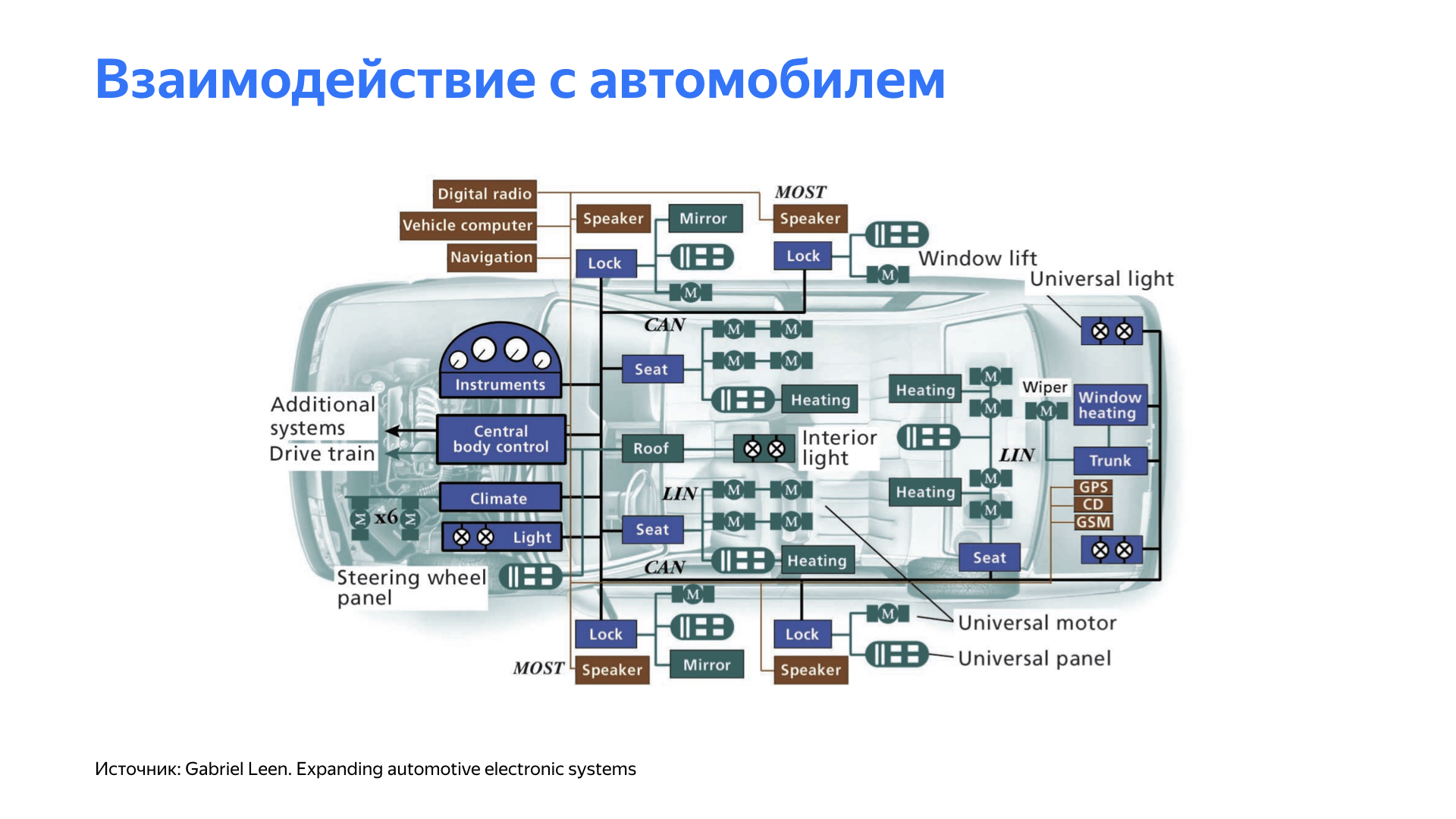
Having studied the features of different platforms, we found that many modern cars have the ability to control their own organs of the car. For example, an assistant controls the steering wheel during parking. Cruise control affects the acceleration of the car, adaptive cruise control or a speed limit system can affect the braking system.
All these systems, as a rule, are closed in cars. And to interact with them, it took the development of a number of specialized devices. In addition to interacting with the car, the system was required to provide a convenient, user-friendly interface for driving the car. And of course, the system should have been simple, straightforward, and very flexible.
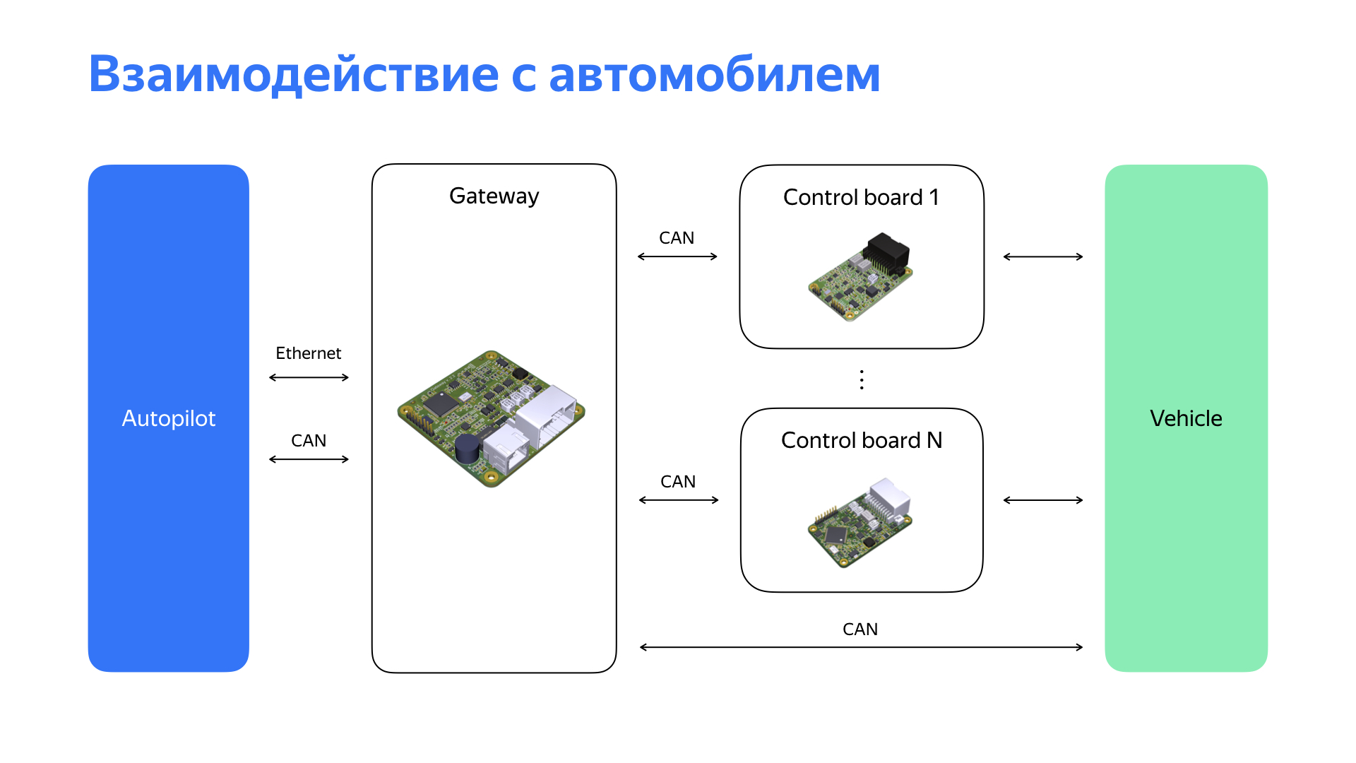
We came to a platform where, depending on the car, small control boards are developed that interact with a specific node. The composition and functionality of these boards differ from platform to platform, but they all come together in one network, where there is a head unit, which we conventionally called a gateway. It monitors these devices. In addition, the gateway provides an interface for autopilot on convenient devices. Here we see Ethernet, convenient for our infrastructure, and CAN, the most popular automotive interface. In addition, our head unit constantly interacts with the car, monitors the condition of components and assemblies. If any deviations are detected, then, depending on their nature, together with the autopilot, a decision is made on further steps.
We decided to implement the board on fairly popular and proven microcontrollers. We took them with a margin of performance and chose those that support the necessary interfaces for work: CAN, Ethernet and analog digital inputs / outputs.
We got a solution that really turned out to be flexible for us and which allowed us to switch from platform to platform with less problems.
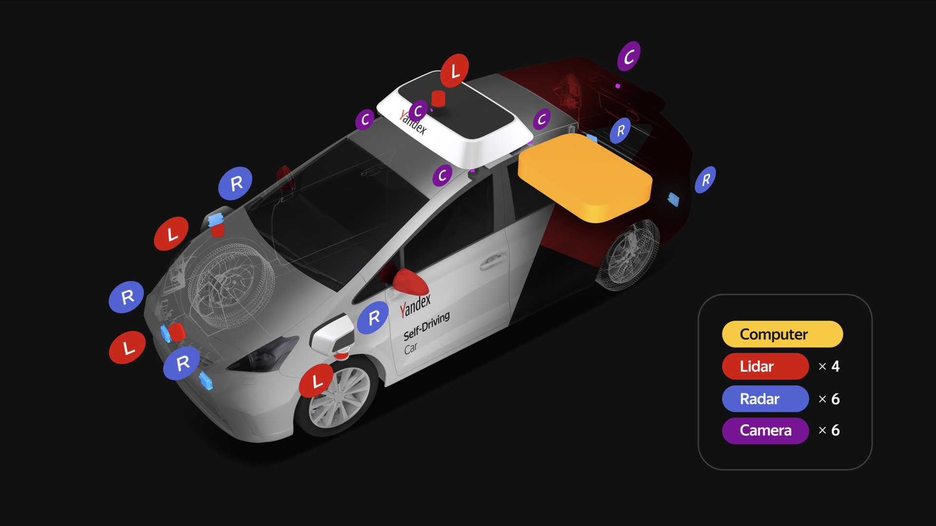
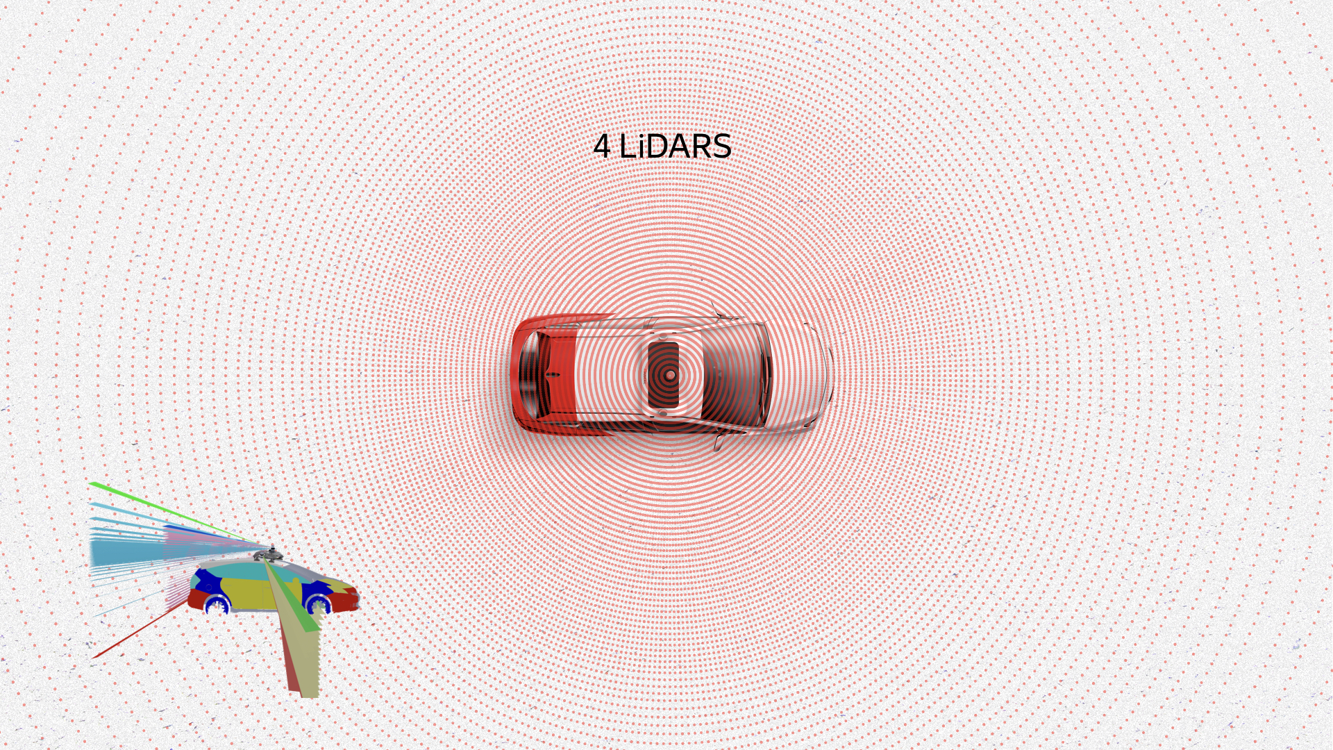
Let's talk about sensors. Each unmanned vehicle has a rich set of sensors. Each Yandex unmanned vehicle has four lidars on the roof and three in the front, six cameras that are placed on the roof, and six radars: two in the rear and four in the front, two of which are located on the sides.
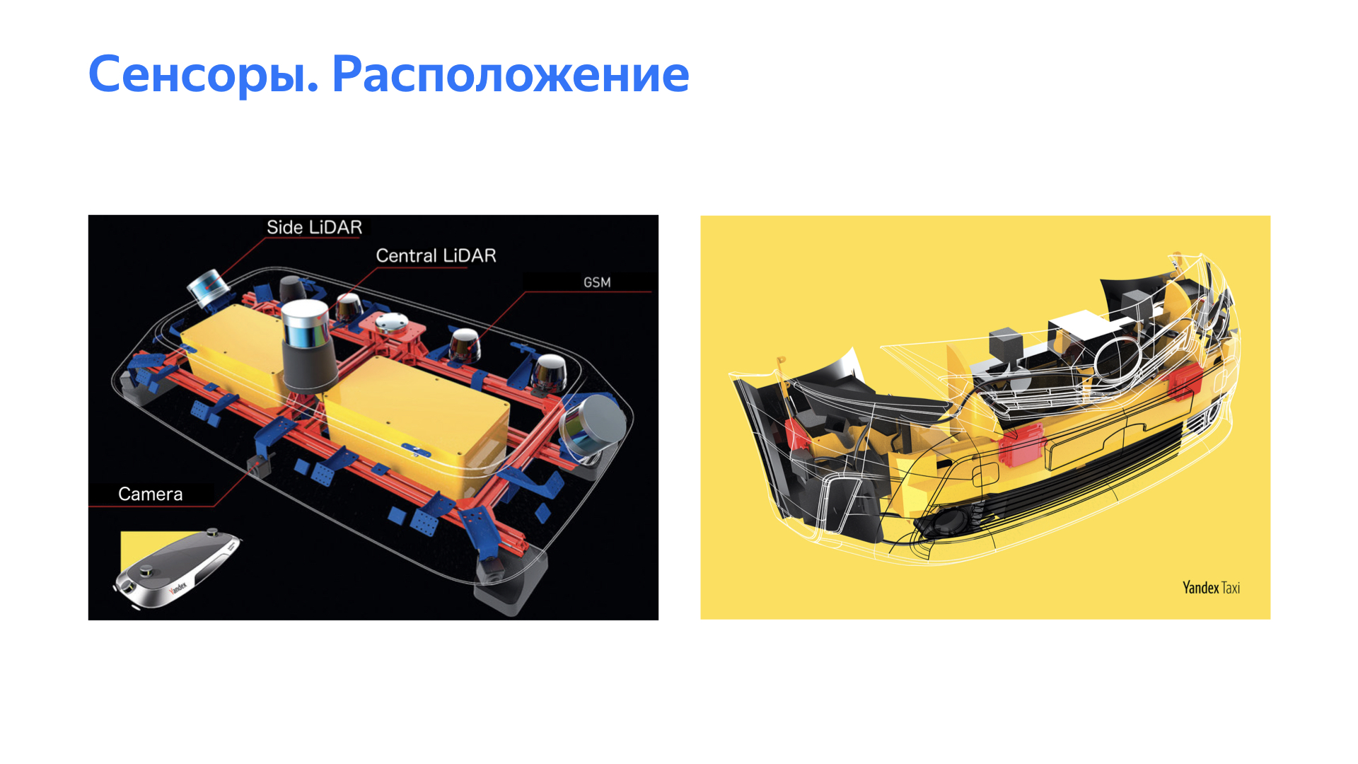
We take radars, lidars, cameras, connect, drive into the computer. But not so simple. It is very important to ensure that the sensor data is adequate and of high quality. We conducted a large number of experiments to understand where to place the sensors, so that we can see the world better and more clearly.
In addition, our designers had to work hard to ensure that all changes in the car related to sensors meet the requirements of certification bodies.
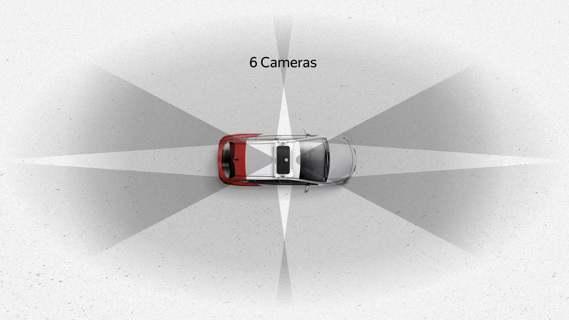
Here's what happened. Six cameras on the roof give a good 360-degree view with significant overlap - dark areas are marked on the slide. These cameras also give a good vertical view. The camera is the only sensor that sees traffic lights, because they can be located in different parts, depending on the intersection and other things.
Radars are another important sensor for every car. They are interesting in that they have a not very wide viewing angle, but a good range. Two frontal radars perform the function of monitoring what is happening ahead, the rear radars in our algorithms are used, as a rule, in rebuilding, overtaking and similar maneuvers. Radars that look sideways are necessary for driving through fairly complex intersections where information from the sensors may not be enough.
Probably the most interesting sensor is lidar. He is interested in the information that comes from him. Here is a point cloud, point cloud, this is data from lidars. They show pedestrians, cars, the road, even the edges of the roadway and other objects. Boxes are already the result of the work of our recognition algorithms.
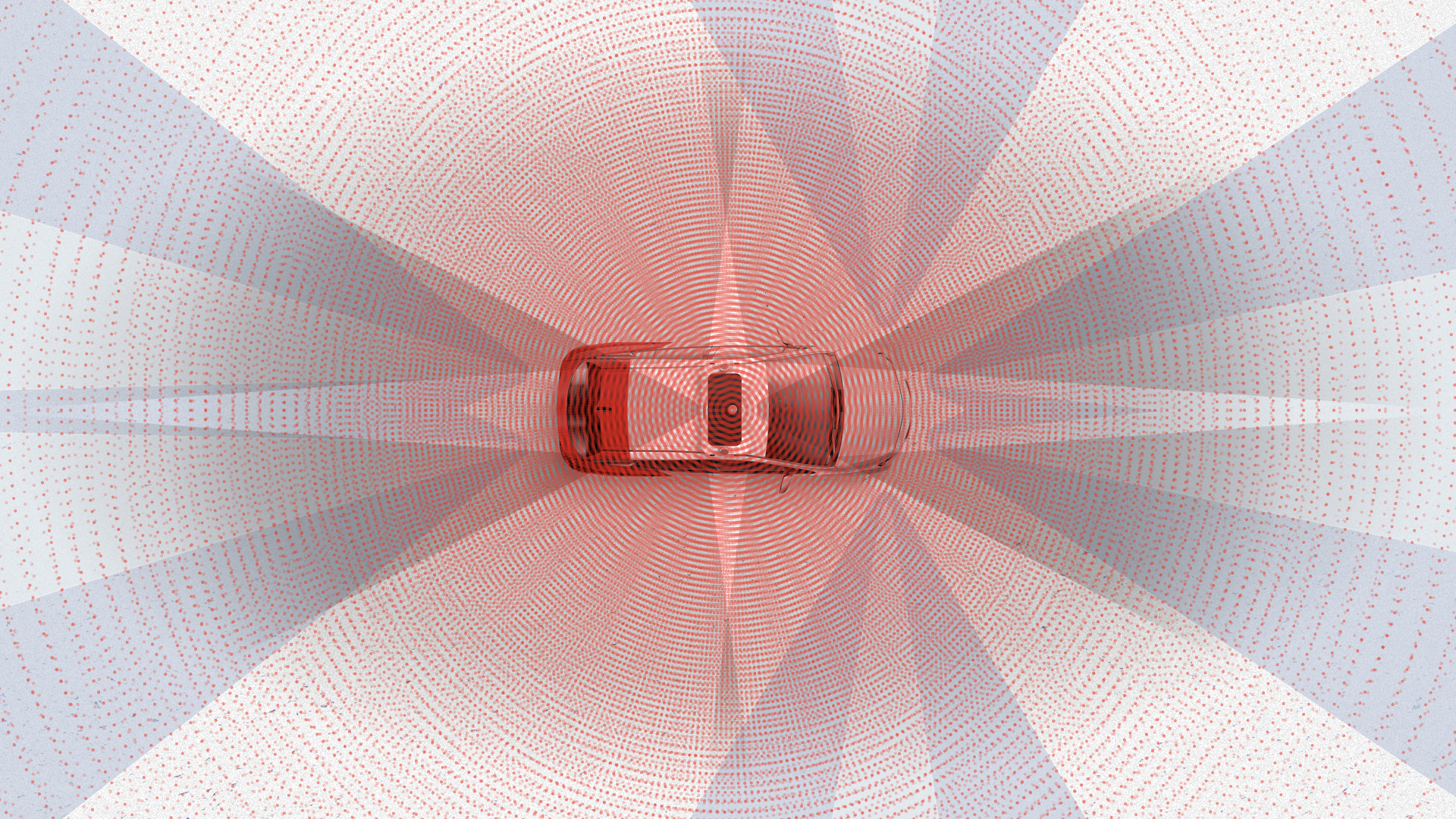
In total, all sensors give approximately the same picture. As you can see, it is impossible not to notice anything around the car with such a set of sensors.
I would like to dwell on two examples that we encountered when we needed to develop hardware. I'll start with the localization case.
The main source is high-definition cards. At each point in time, an unmanned vehicle compares data from lidars with these cards. Based on such a comparison, he gets his location with centimeter accuracy. GPS, Glonass or any other satellite navigation is simply not suitable for working with an unmanned vehicle due to its low stability, high dependence on external conditions, weather, noise, interference. In the city, all this is significantly complicated by signal overlaps, reflections from buildings, etc. But where do we get these cards? We build maps ourselves, using our unmanned vehicles with a set of sensors.
To build these maps, we need lidars and some kind of reference on the ground. You need to somehow get your coordinate. GPS could initially give a coordinate, but its accuracy is not very high. As I said, the accuracy of GPS is affected by atmospheric conditions, interference, and in the city there are also reflections.
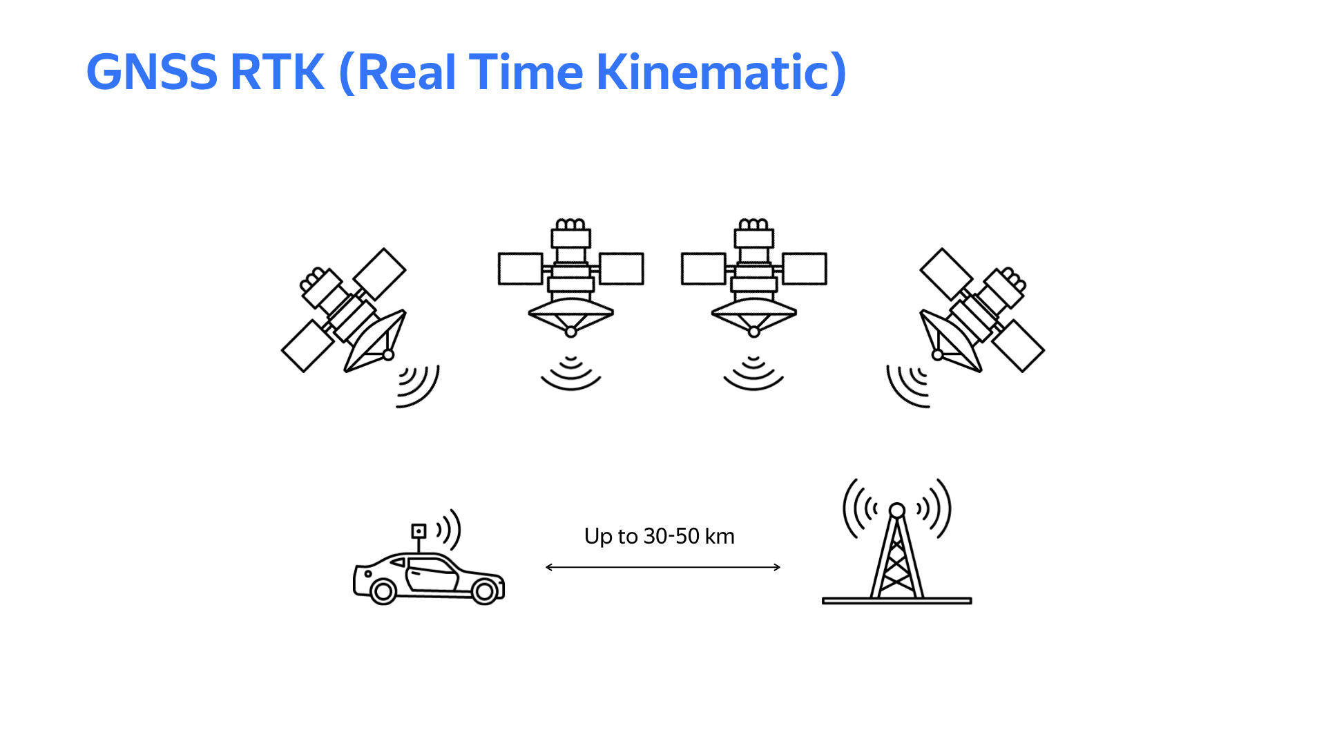
Realtime kinematic technology comes to the rescue. The bottom line is: somewhere on the ground a fixed base station is installed with the same receiving device as on a car. If the distance between the car and the base station does not exceed 30 km (in some cases 50 km), then the satellite data received by the car and the base station will be approximately similar. But the base station, knowing its exact coordinate (it is motionless) and calculating the coordinate according to satellite data, receives, conditionally, a calculation error. Based on this error, amendments are generated that are sent via car to the car via the Internet. The car, taking into account the received corrections when calculating the coordinates by satellites, gets its coordinate with centimeter accuracy. Of course, to work with this system, you need a good Internet channel and good weather so that the GPS signal is stable.
To get a working device with RTK support on a car or base station, you need software. Libraries providing RTK RTKLib features are publicly available. There are different variations with different features. Libraries typically require a Linux environment and satellite navigation modules that provide raw data.
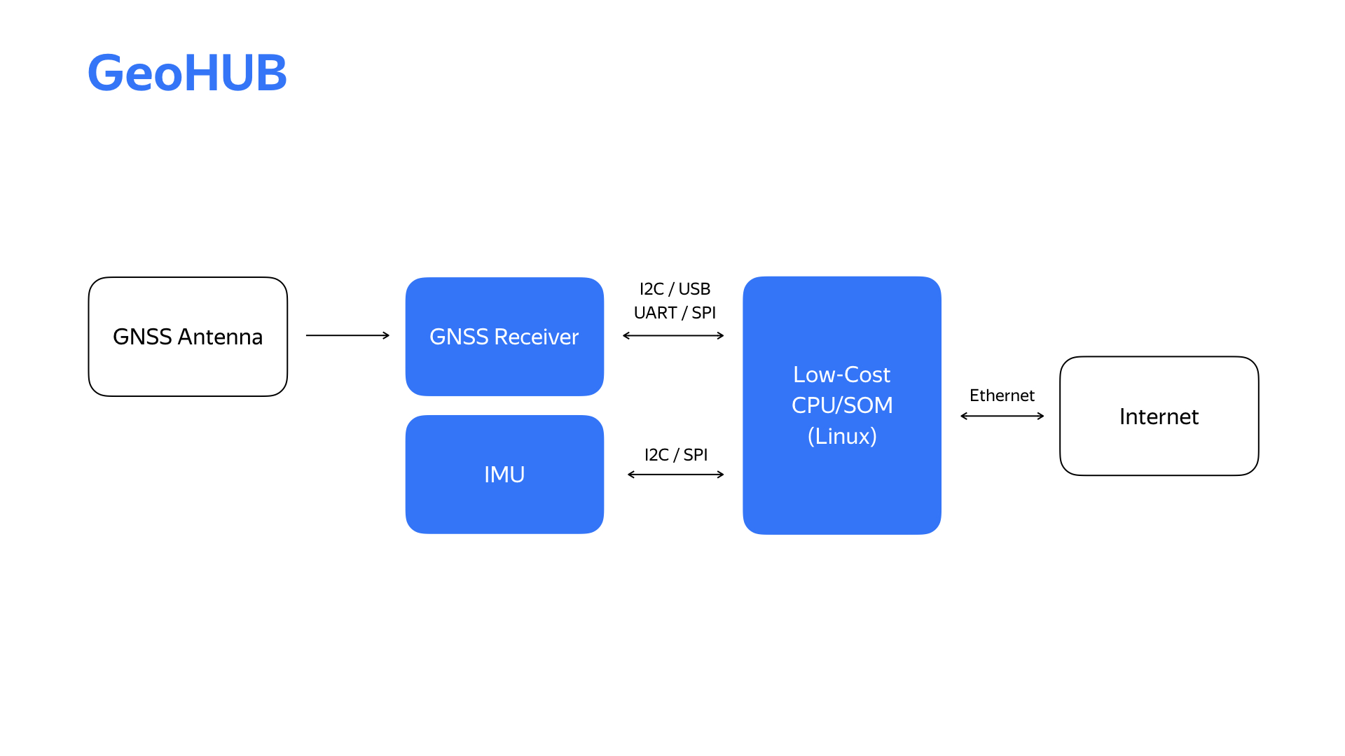
After conducting a couple of experiments, prototyping a couple of things, we got a block diagram of the localization block, which we called GeoHub.
In addition to the specified satellite navigation module, there is also a module of inertial measurements, which we use in the localization system. The Internet is now coming via the Ethernet interface that is convenient for our infrastructure.
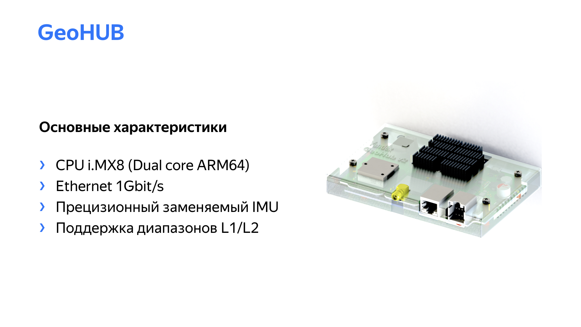
Here is the second device, its second generation and the main technical specifications.
We replaced the inertial measurement module and the satellite signal module. As a result, it allowed us to perform a series of experiments on a car and choose the module of inertial measurements that is optimal from the point of view of various parameters, and as for the satellite signal module, we were able to switch to a dual-band receiver in the process, which significantly improved the quality of positioning.
Why develop your device when you can certainly go to the market and buy something similar? The answer is that for us, one of the most important parameters is the flexibility of the device. Due to the rapidly changing requirements in the project, emerging new functionality, we need to be able to respond very quickly to this. Only having within the project, in-house, the development of hardware and software, we get a really high speed of development of these changes.
Another interesting sensor from the point of view of an unmanned vehicle is the camera. Okay, there is a camera in every phone and laptop. What could be complicated here? But let's see what problems you may encounter when using the camera in a drone.
The first problem is the flickering of LED light sources. Most traffic lights are just such sources. The video stopped at the moment when, due to flickering, the red signal almost disappeared.
For this problem, there are hardware solutions embedded in the sensor, but in order to work well and with high quality, you need to be able to actively interact with the sensor.
The second requirement for cameras is a high dynamic range, that is, the ability to work in any light conditions, both at night and in bright sunshine. The presence of HDR is also important, that is, the possibility of combining frames with different illumination into one to get a better picture.
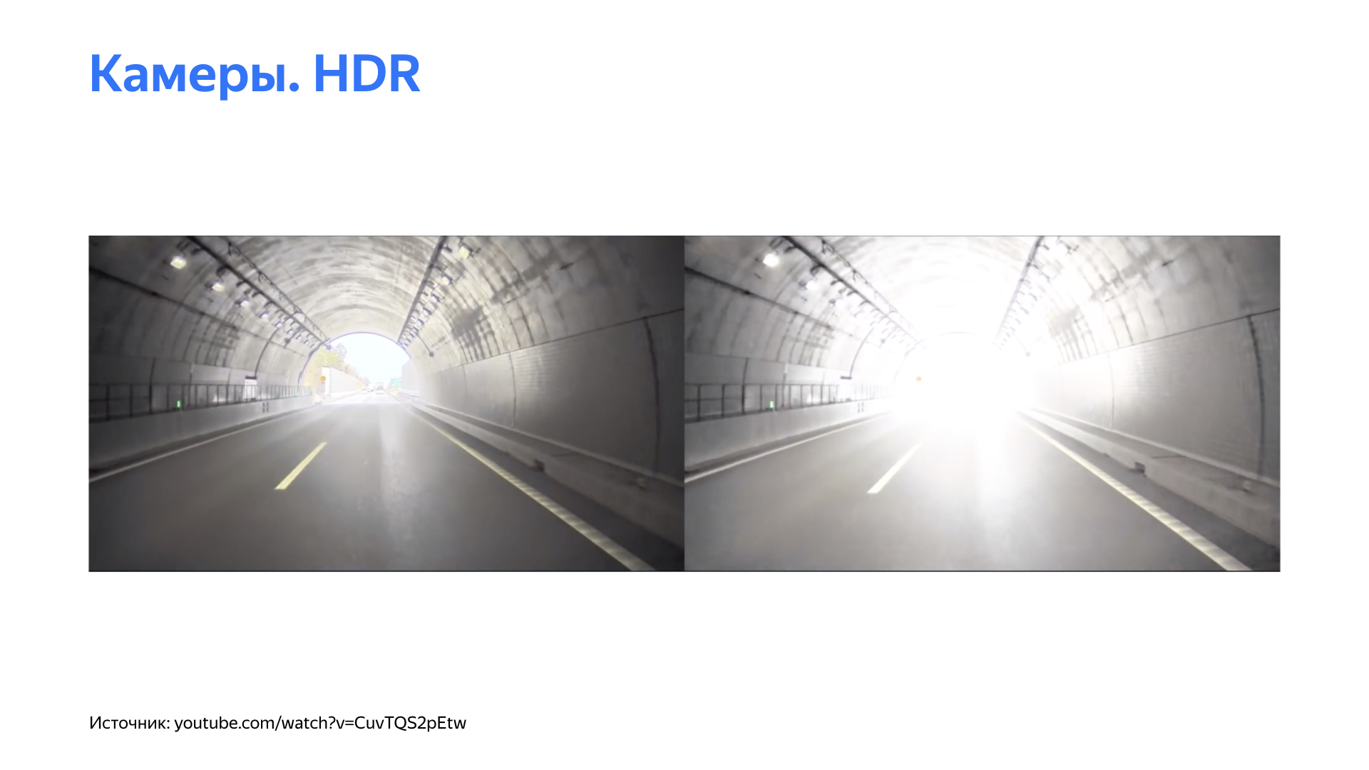
On the left is an example of a picture where where the HDR function is used, and on the right - where it is disabled.
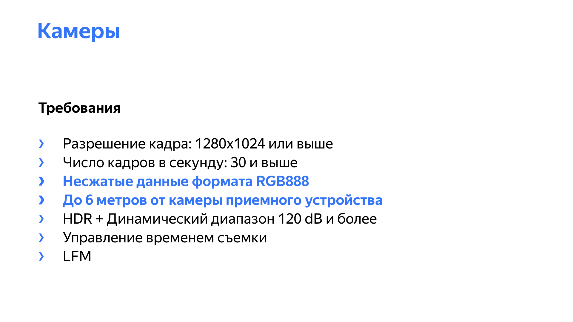
In addition, we, of course, must get a picture with a sufficient resolution and a sufficient frame rate. On the slide, a couple more points are highlighted, inherent in unmanned vehicles, including. The camera should produce an uncompressed video stream, preferably of the RGB888 format, because our networks, algorithms work with this format, they want to receive frames in this format.
Most cameras, ready-made solutions on the market, provide data in a compressed form - H264, MPEG. The problems here are simple: we lose quality during compression and introduce a delay in compression and decompression. Delay can be non-deterministic, especially with a high system load. A camera with Full HD resolution and a frequency of 30 frames per second with a bit rate of 16 bits per pixel produces a stream of about gigabits per second of pure video data.
In addition, cameras are usually located at a distance from the receiving device, and in the car, especially during some experiments, they can be located generally on the other end of the car. We needed cameras that allow the entire uncompressed video stream to be transmitted at a distance of 6-8 meters, taking into account the cabling. For a Full HD camera with 16 bits per pixel, the video stream is 1 gigabit, which no longer allows the use of gigabit Ethernet, since various service data and so on are involved in the transfer. Ten gigabit Ethernet is not entirely appropriate. It is expensive, high power consumption, high heat dissipation, increased complexity of the network infrastructure.
Yes, there are other interesting interfaces. I would like to talk about two of them that we have worked with. They are provided by Maxim Integrated and Texas Instruments. The peculiarity is that the video stream is serialized into data that goes on a simple physical level, in this case through a coaxial cable, at a speed of 3-4, sometimes 6 gigabits per second. In addition, this interface allows you to use the return channel to control the camera on the same coaxial cable. And on it the camera power can go. All of the above makes this interface very attractive.
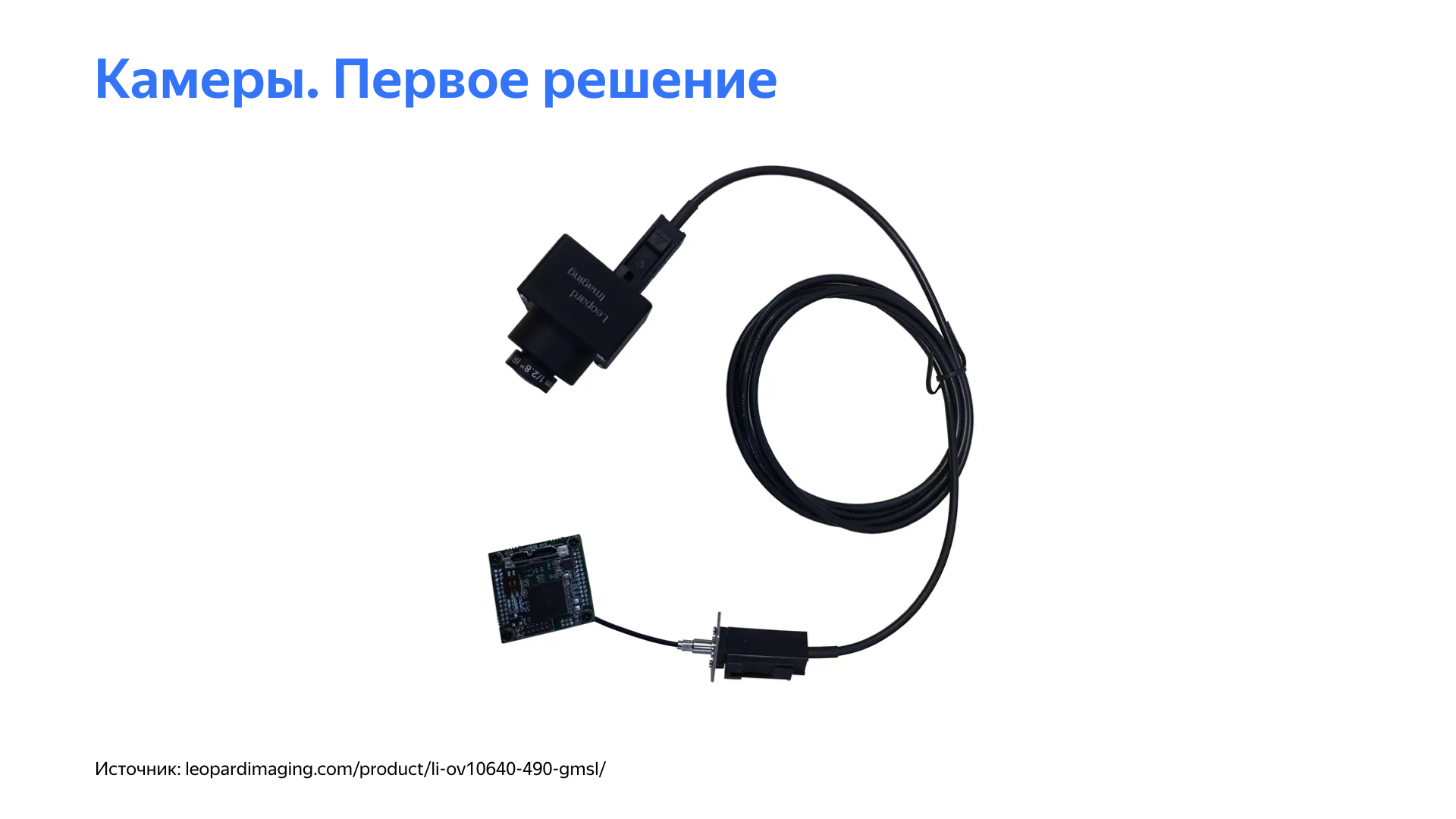
When we started, we found a solution in the market that basically satisfied most of the requirements. We used it for some time at the start of the project.
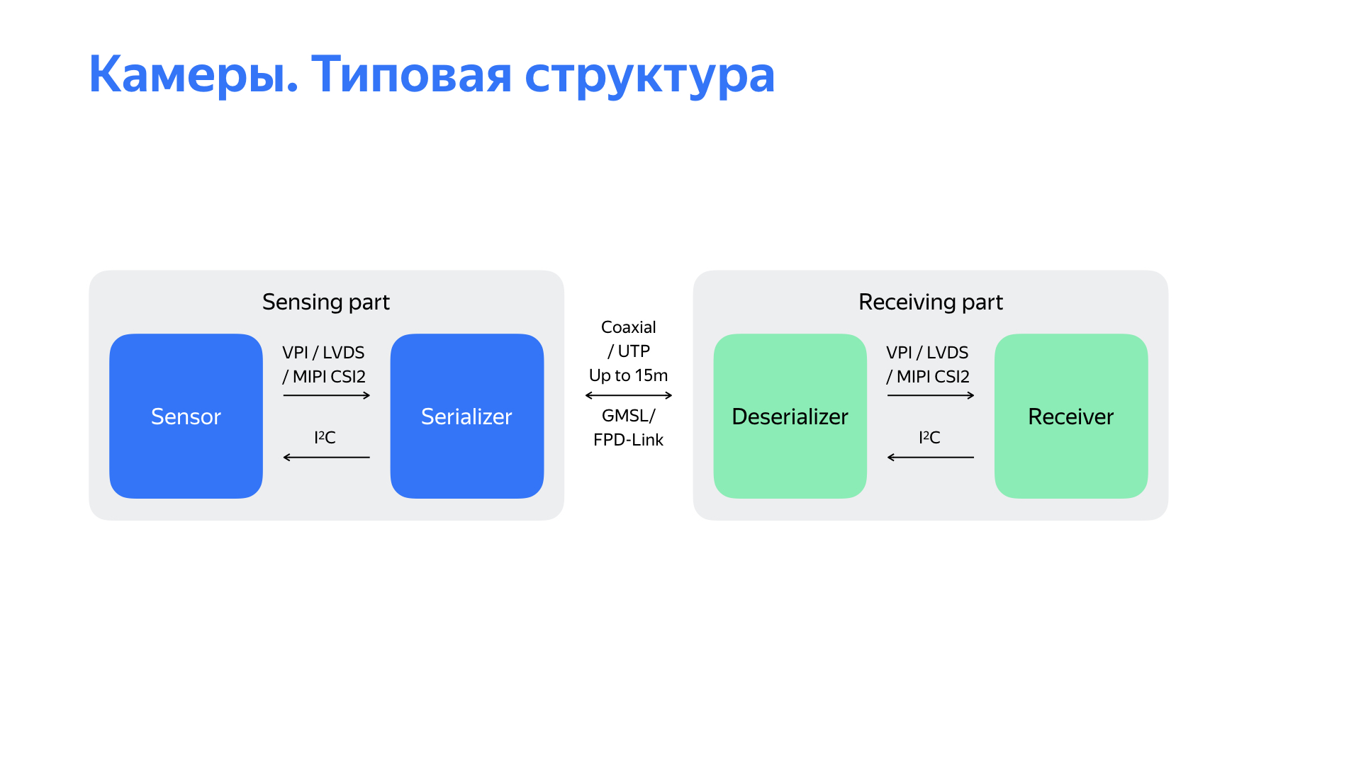
The block diagram of the solution is in front of you. This is a sensor from which data is serialized to the GMSL / FPD-Link interface. At the receiving part, which can be removed up to 15 meters, the data is deserialized and transmitted to the receiver. In our solution, this receiver then provided data via the USB 3.0 interface.
But starting to use this solution, we encountered a number of unpleasant problems. The main problem - the solution worked extremely unstable, “fell off” in the process, the cameras did not start well at the start of the autopilot. In addition, the solution did not allow to adjust the parameters of the sensors themselves in order to improve picture quality. There were also a number of problems. For example, it was difficult to get the exact timestamp of the camera, the shooting time, which is quite important, because at a speed of 15 m / s with a delay of 100 ms the car already travels one and a half meters, and this can very negatively affect the perception algorithms.
There was another interesting point. The output interface of the selected solution was USB 3.0, and we found that it was extremely noisy. How do we understand this? We had two cars not connected to anything. On one, they launched the camera, on both the satellite navigation signal sank very much. Then we began to study what was going on.
Having analyzed all these shortcomings in general, having studied the structural diagram in front of you and so on, we came to the conclusion that the problem is in the receiving part. Then they began to think what to do with it. We looked at what is on the market, solutions of other teams, and came to the conclusion that we need to make our own receiving device that will work with the camera via the GMSL or FPD-Link interface.
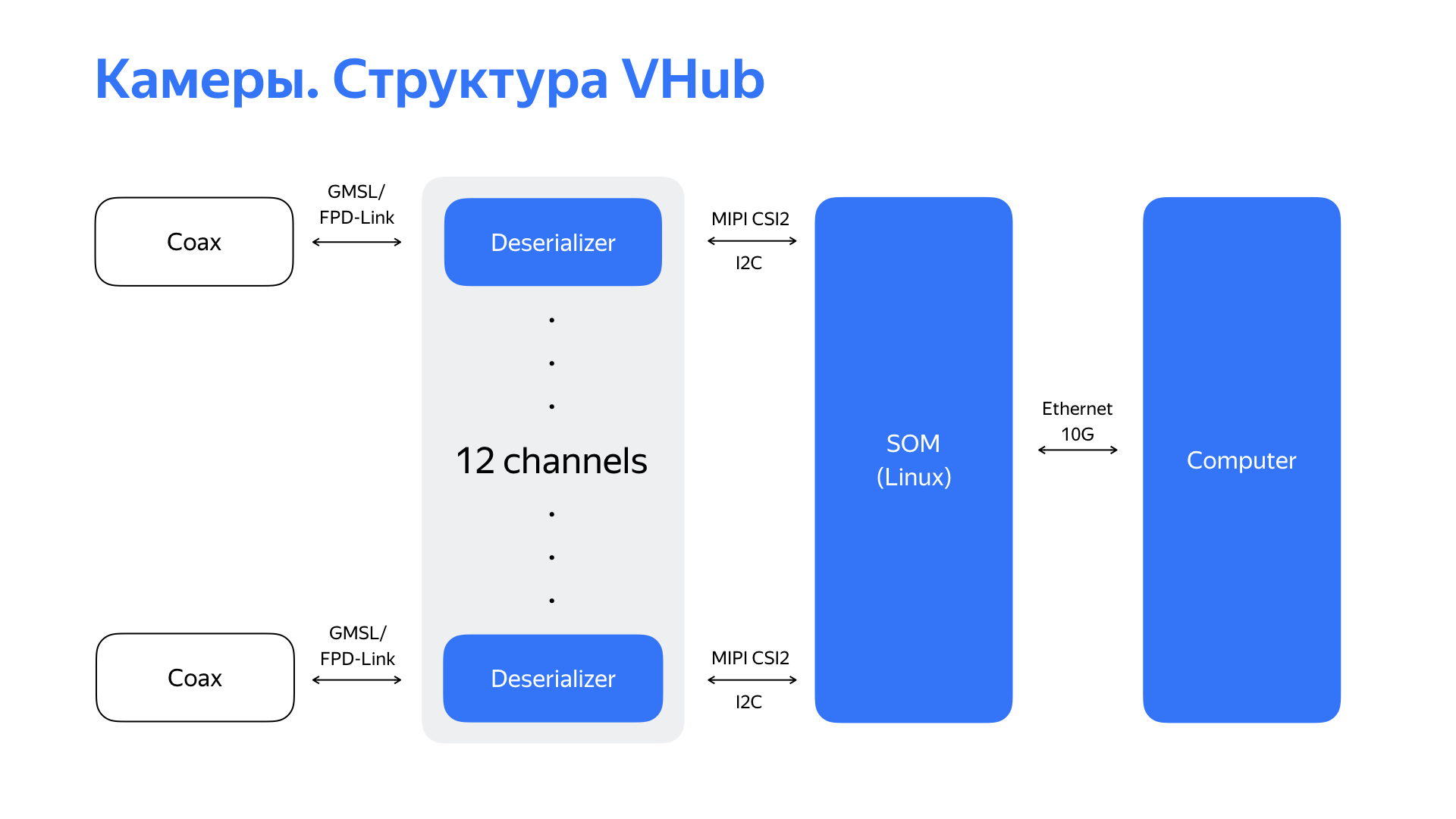
We took deserializers, which, as a rule, have a MIPI CSI2 interface, and started looking for a module or processor that could support this interface. And we found an interesting solution with six MIPI CSI2 interfaces, as well as high performance and rich peripherals. This allowed us to ultimately use the 10 gigabit Ethernet interface convenient for our network infrastructure as the output interface of this device. Having received GMSL / FPD-Link data from 6 cameras (or, in some cases, from 12 cameras), having processed them, the device transfers the already processed video stream further to the computer via 10-gigabit Ethernet.
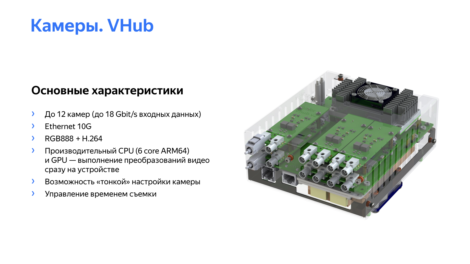
Here is the solution itself and its main characteristics. Having developed such a thing, we learned not only how to reliably work with 6 or 12 cameras, but also got the opportunity to fine-tune the cameras. This made it possible to improve the quality of the image, which positively affected the operation of perception algorithms. We also got a clear understanding about the time of shooting the frame, learned to manage this time. And high-performance CPUs, the computing power of the module allowed us to carry out primary video processing with minimal delays right on the module.
The hardware codec of this module also allowed to compress video data for subsequent storage in the logs.
We had to work not only with localization sensors and cameras. We had to develop hardware solutions for almost all the sensors that we use. All this was done to solve the increase in the reliability and quality of the data on which the detection and perception algorithms depend. And it depends on them how optimal the solution issued by the autopilot will be.
Okay, we learned how to drive a car, worked on sensors, positioned them well, taught them to give us a high-quality picture. What other work do the engineers of embedded systems, hardware developers on our project? We monitor not only the development of sensors that have become routine, but also alternative sources of information. We are constantly exploring alternative accelerators of neural networks and other algorithms, including those using FPGAs. And it is difficult to imagine the development of the project without interacting with an experienced automaker.
The new platform is always a challenge for embedded developers, designers, high-level software developers.
The sphere of unmanned vehicles is now at a very active stage of development. As an engineer, I am very pleased to observe this, but it is much more pleasant to participate. And not far off is the time when it will become quite usual for us to get into a car and, heading for the place we need, go about our business in comfort and safety. That's all, thanks for your attention.