
Greetings Habroyuzery. My name is Eugene and in a series of articles I want to talk about the process of developing and testing a collision avoidance system for industrial equipment and people working with it side by side.
But first a little story. One northern city is our immense. The city has a large mine, which in essence is the main place of work for residents of the city. Friday, the working day has already passed in the afternoon. Miners on the horizon of 720 meters celebrated a colleague's birthday with a drink of alcohol smuggled into the site secretly. And then one drunken miner went to aerate before going to the surface, but in the process he got a little tired and dozed off on the rails of the underground railway for ore removal. He was awakened by an electric locomotive, the driver of which in the dark did not notice the unfortunate miner, dozing off the rail. As a result of a collision of an electric locomotive at a miner, he lost his wrist. A terrible story, and many similar stories from other parts of Russia each time make different leaders think. And what can be done to make such stories less or never more. This is where the request for a system begins, which will solve the problem of preventing equipment hitting people.
The background of the issue that prompted us to start developing such a system in 2016 is as follows. Mining is one of the most dangerous occupations in the world. And in our country, this is one of the key sectors of the economy after oil and gas production. There are two ways to extract minerals all over the world: open (surface) and underground.
We, as a developer of positioning systems, have long been engaged in the positioning of miners in mines, and nowadays, practically in all mines, the positioning problem has been solved to one degree or another. But incidents related to collisions of mining equipment and hitting equipment on personnel unfortunately continue to occur. In the West, this issue began to be addressed as far back as 2006-2010 by the development and implementation of collision avoidance systems. First of all, such systems were introduced in quarries, since similar incidents more often occurred there. Since March 2019, the installation of collision avoidance systems has become mandatory in Russia, but not in quarries, but in mines. And here we come actually to TK and the request for such systems.
All mining enterprises in Russia are required to comply with industrial safety rules. Rostekhnadzor (Federal Service for Ecological, Technological and Atomic Supervision) monitors compliance with these rules and we first of all took into account the requirements put forward by this service when developing the system. But since the requirements for collision avoidance systems in our country are so far broadly stated , in drawing up TK for development, test scenarios and acceptance criteria, we relied on an international document developed by EMESRT (Earth Moving Equipment Safety Round Table) . This organization brings together mining companies, government agencies, mining equipment manufacturers, service and engineering companies around the world.
This organization has developed a classification of management and safety systems for mining:
- Level 7 - Operator Awareness
Technologies that provide information to enhance the operator’s ability to observe and understand potential hazards in the vicinity of equipment.
- Level 8 - Advisory Control
Technologies that provide alarms and / or instructions to enhance the operator’s ability to predict potential unsafe actions and necessary corrective actions. - Level 9 - Intervention Control
Technologies that automatically intervene and take some form of equipment control to prevent or reduce the consequences of a hazardous situation.
The basis for the development of the system and the program for subsequent tests and test scenarios was taken as the document Vehicle Interaction Systems , which spelled out the main scenarios and situations that arise during the operation of equipment and people in mining and possible incidents with them.
When developing a system for mining equipment, it is necessary to exclude the following dangerous situations or minimize harm from them (minimizing the consequences of an incident):
- Injury due to workstation design and external structures
- Injury or hospitalization resulting from physical and / or mental fatigue
- Damage from impaired visibility (including distorted or impaired visibility) or a violation of hazard awareness in various operating conditions
- Damage from limited or difficult viewing by the operator of the environment and the operation of the tool
- Collision damage caused by the movement of people and vehicles in the operator’s blind zone
- Harm from loss of stability of the machine during operation, movement, articulation
- Damage from improper use of equipment controls, incorrect / inaccurate calibration, or inefficient maintenance due to poorly designed controls and displays
- Damage from misinterpretation of information on displays or labels
- Harm, including mental overload, from missed warnings and alarms that are ignored or not heard
They contain requirements, both for the system itself and for the type of devices, visualization of notifications and notification methods.
You must admit that there are much more requirements for collision avoidance systems than in the Russian edition of industrial safety rules for mining companies ( Order of December 11, 2013 No. 599 On the Approval of Federal Standards and Rules in the Field of Industrial Safety “Safety Rules for Mining and Solid Processing minerals " ), where only one point is written:
Point: 325 Transport vehicles operating in mines for mining shall be equipped with collision avoidance systems. The collision avoidance system should provide timely notification to the driver about the presence of people and vehicles within the radius of the vehicle trajectory.
It is the much larger list of initial requirements for the collision avoidance system described by EMESRT and the consideration of these requirements in the development of the product that will meet all existing and new requirements that may be added to the relevant documents and regulations for Russian mining enterprises in the future.
So we came to the key scenarios of the work of equipment and people in which a collision avoidance system should determine the danger and warn all participants in such a situation about it.
List of mining scenarios:
- P1-Man is located directly next to the machine
- P3-Man is monitored when working with machinery and equipment
- P4-Man sits in or out of the cab
- L1-Frontal approach with a standing machine
- L2-Approaching the machine when reversing with a standing machine
- L3-Rapprochement of 2 cars when moving each reverse
- L4-Rapprochement of 2 cars when driving one by one
- L5-Departure of two cars moving towards each other
- L6-Two cars move backward, with one car overtaking the other
- L7-Rapprochement of 2 moving cars and overtaking one of them
- L8 Zero Visibility Approach
- C1-Rapprochement of 2 cars to meet each other when driving along a bend of the road with insufficient visibility
- C3-Approaching a vehicle moving forward with a vehicle moving backward in bending conditions with insufficient visibility
- T1-Rapprochement of 2 cars moving in the same direction at the intersection
- T2-Rapprochement of 2 cars towards each other with the intention of turning at the intersection of one of the cars
- T3-Rapprochement of 2 cars moving in the same direction at a T-junction at an angle of 90 degrees
- T4-Rapprochement of 2 cars moving in the same direction at the intersection of 2 technological roads
- R1-Machine with a rotating working tool works next to another machine
- R2-Machine reloads materials to another machine
- O1-machine comes close to a fixed structure, wall or stationary equipment
- V1-Magin enters a restricted area where traffic is prohibited
- V4-Machine moves without operator control
- V6-Machine moves through the territory where there are a large number of other cars and people, for example, a workshop
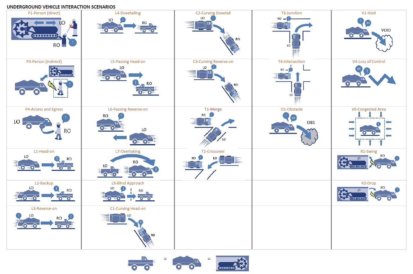
There are 24 scenarios in total, which cover 99% of all typical tasks solved in underground mining, where self-propelled equipment, transport are used and people can be present.
Next, I will tell you how we chose the technologies for developing the product, what we had to go through when creating it and what happened at the output, and how each of the scenarios described above was tested.
Technologies and solutions for creating a collision avoidance system
Since 2016, we have been developing such collision avoidance systems, and you can read about it in the article on Habré here .
in 2016 it looked something like this 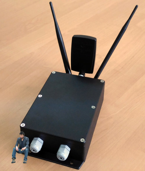
During this time, we changed the technology from the then obsolete Nanoloc technology to the more promising UWB technology . We wrote more about UWB technology on Habré here and here .
What is the advantage of UWB (UWB) technology for positioning objects?
- High positioning accuracy: up to 10 cm.
- Resistance to reflections of radio signals in direct visibility conditions.
By 2018, based on UWB technology, a collision avoidance system was developed and went through several stages of development.
It looked like the first prototype antenna
At the first stages of development, the antenna board was built into a flashlight for special equipment. The flash frequency of the flashlight determined in which zone the personal tag is located.
 "alt =" image "/>
"alt =" image "/>
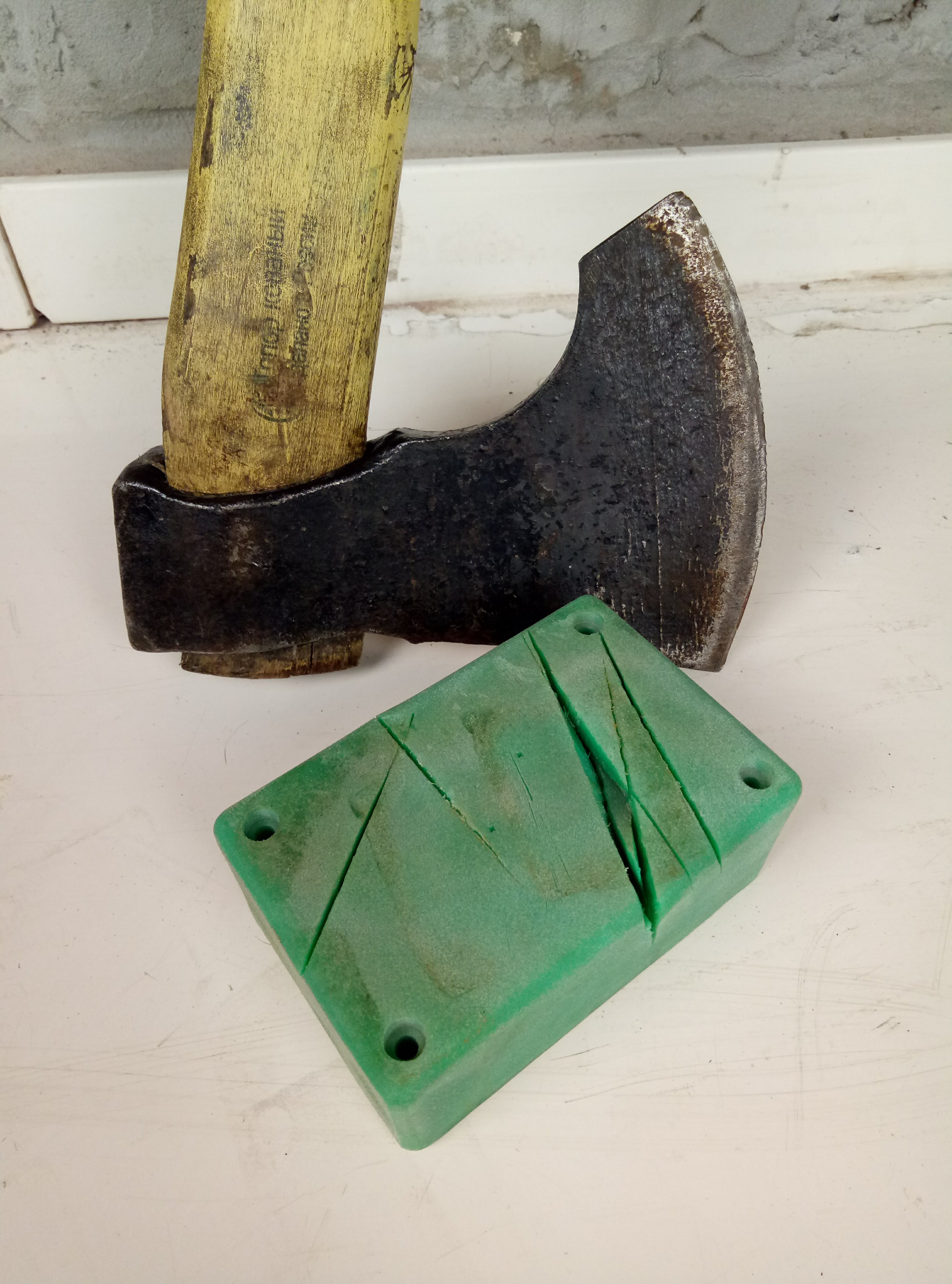
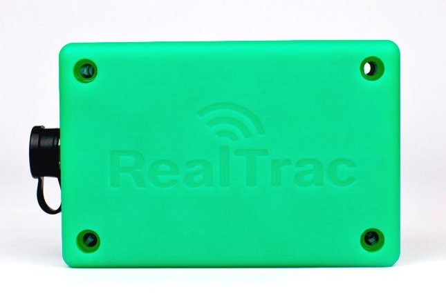
One of the stages of testing a new antenna housing
The antenna housing is molded from a heavy-duty green polymer. The color was selected based on the fact that it should not be found in the environment where the system will be used.
Now the system consists of the following components:

Tag (TAG) - a chip with support for UWB technology, built into the miner's flashlight or a separate device based on it.
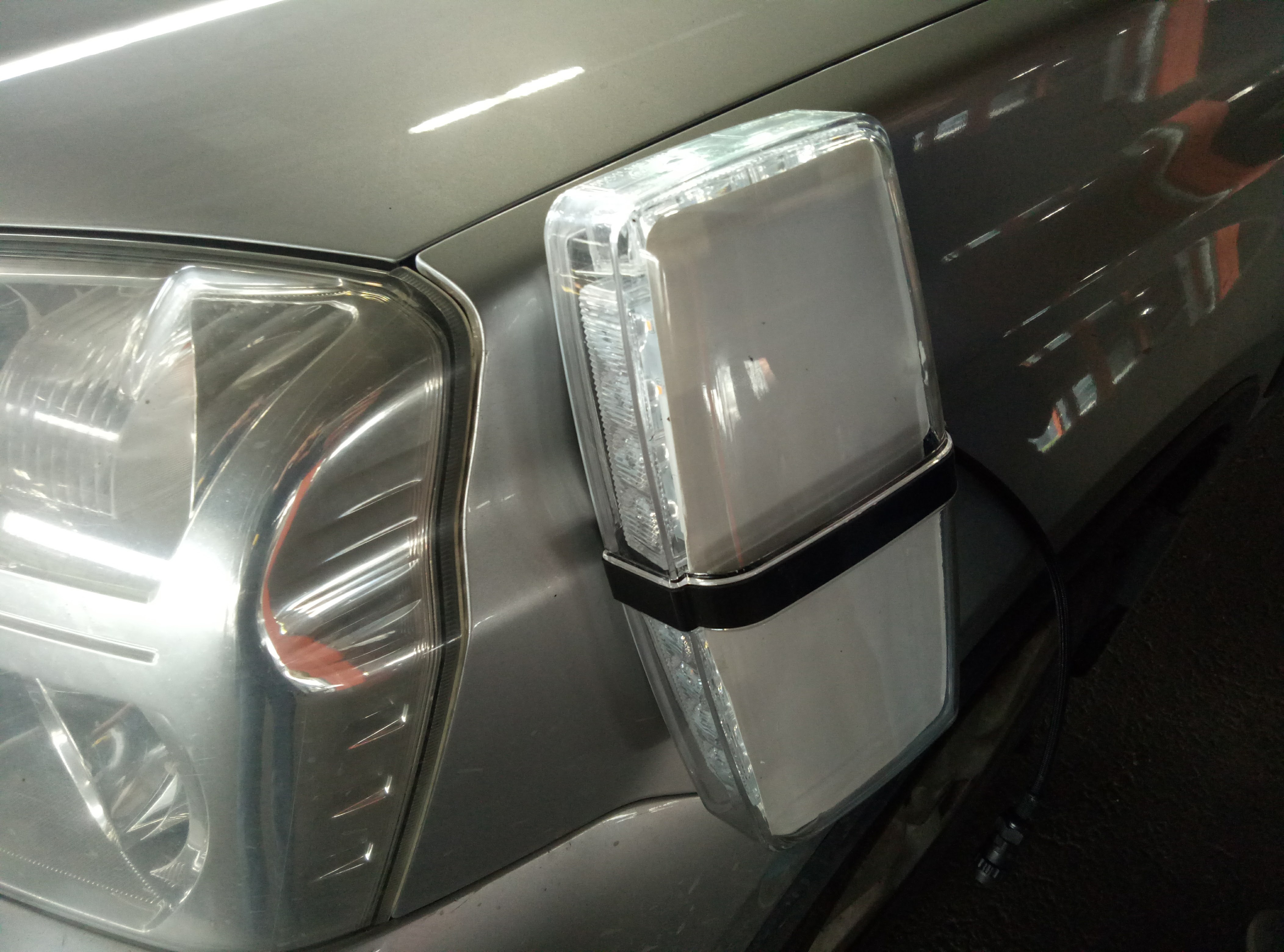
Antenna (VBU) - is installed on the skin of the vehicle. It also contains a UWB chip, which determines the distance to another UWB chip by ToF (Time of Flight).
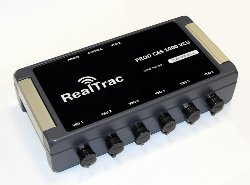
The control unit (VCU) is a microcomputer that processes the received measurements from the antennas and, using a mathematical algorithm, determines the location of the tag relative to the vehicle and sends the data for visualization to the driver’s display.
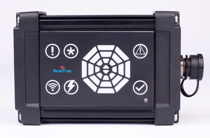
Display (VOD) - provides a visual representation of information about the location of tags relative to the car.
At the heart of UWB positioning technology is the chip of the Irish company Decawave. The chips have their own antenna, thanks to which they can measure the signal transit time between themselves. Since VBU has the same UWB chip as in the tags, they detect each other in the presence of radio visibility and also measure between themselves. This principle allows you to determine the time of flight of the signal, as between the antennas of vehicles, so between the antenna and the tag.
From here we get two areas of control:
- transport-vehicle (Vehicle to Vehicle or V2V)
- transport-person (Vehicle to Personnel, V2P)
The principle of the system
The system is based on the principle of creating around the vehicle 3 zones of control of dangerous proximity. Moreover, the zones can be of any shape and take into account both the design features and the vehicle motion parameters.
Attention Zone
Warns employees about the presence of vehicles, equipment, etc. at a short distance.
The system signals a possible dangerous approach and allows the driver and the miner to draw attention to the fact of approaching another object.
Antennas (VBUs) radiate a signal around the UWB vehicle in search of other antennas (VBUs) or personal tags (TAGs) in the radio visibility zone.
If other antennas (VBU) or personal tag (TAG) are detected in the “Attention” zone, the distance from the antenna (VBU) to the object is measured.
Data on distance measurements is transmitted to the control unit (VCU), where the location of the detected objects at a distance, direction and zone is calculated.
The calculation result is displayed on the driver display (VOD).
Attention area on display 
Danger Zone
It fixes dangerous rapprochement and attracts the attention of workers, it can slow down equipment and transport.
The system notifies of a possible accident and allows you to draw the attention of the driver and the miner to the fact of approaching another object.
The driver sees on the display (VOD) in which zone the detected object is located and when it approaches the vehicle, the object will move from the “Attention” zone to the “Danger” zone on the display (VOD). At the same time, a light and sound warning (VOD) will appear in the cabin when the object enters the “Danger” zone, flashing beacons and sound warning will be turned on both in the driver’s cabin and on the outside of the vehicle. At the same time, a sound and light warning will also be activated on the employee’s personal tag (TAG) or in the cab of another vehicle equipped with the RealTrac Collision Avoidance product.
Danger zone on display 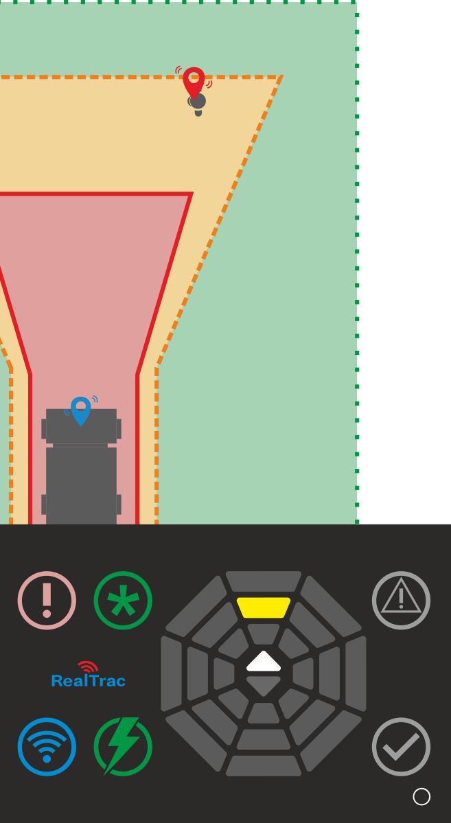
Crash Zone
It generates an alarm when another object equipped with a system enters the Alarm zone.
When an object enters from the “Danger” zone into the “Accident” zone, all means of alerting the driver of the vehicle are included. A red hazard signal lights up on the driver's display (VOD) and a constant audible alert sounds. The miner’s personal tag (TAG) also includes sound alerts and vibration alerts to indicate that they are in the Accident zone.
Crash zone on display 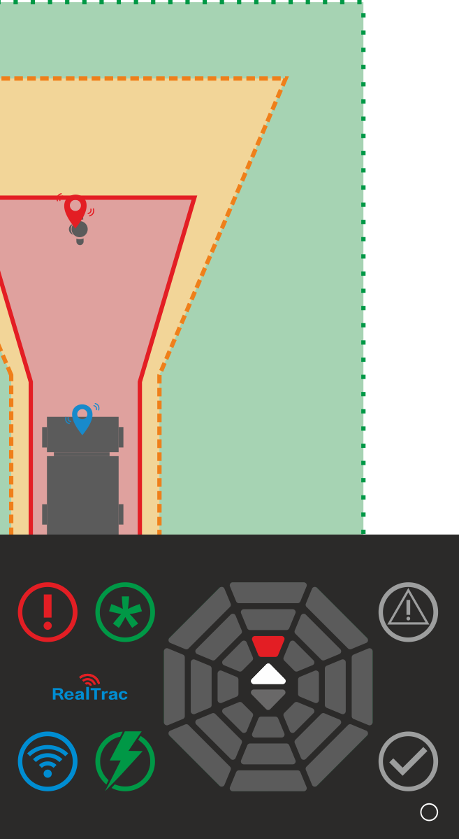
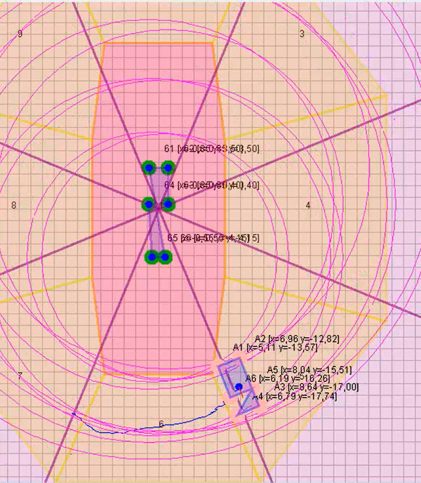
This is what the control zones look like in the collision avoidance system configurator. The antenna installation points on the vehicle and the tag installed on another vehicle are visible. Grid pitch 1 m.
This is the principle of the system described in theory. How all this looks in practice, I will tell in the second part of the article in a week.
If you have questions, write in the comments.