This is a myth that is quite common in the field of server hardware. In practice, hyperconverged solutions (when all in one) need a lot for what. Historically, the first architectures were developed by Amazon and Google for their services. Then the idea was to make a computing farm of the same nodes, each of which has its own drives. All this was combined by some system-forming software (hypervisor) and was already divided into virtual machines. The main task is a minimum of effort to maintain one node and a minimum of scaling problems: we just bought another thousand or two of the same servers and connected nearby. In practice, these are isolated cases, and much more often we are talking about a smaller number of nodes and a slightly different architecture.
But the plus remains the same - the incredible ease of scaling and control. Minus - different tasks consume resources differently, and somewhere there will be many local disks, somewhere there will be little RAM, and so on, that is, with different types of tasks, resource utilization will drop.
It turned out that you pay 10-15% more for ease of setup. This caused the myth from the title. We searched for a long time where the technology will be applied optimally, and found it. The fact is that Tsiska did not have its own storage systems, but they wanted a complete server market. And they made Cisco Hyperflex, a local storage solution on nodes.
And this suddenly turned out to be a very good solution for backup data centers (Disaster Recovery). Why and how - now I will tell. And I will show cluster tests.
Where to
Hyper convergence is:
- Transfer disks to compute nodes.
- Full integration of the storage subsystem with the virtualization subsystem.
- Transfer / integration with the network subsystem.
Such a combination allows you to implement many features of storage systems at the virtualization level and all from one control window.
In our company, projects for designing backup data centers are very popular, and often it is the hyperconverged solution that is often chosen because of the heap of replication options (up to the metro cluster) out of the box.
In the case of backup data centers, it is usually a question of a remote facility on a site on the other side of the city or in another city in general. It allows you to restore critical systems in the event of a partial or complete failure of the main data center. Sales data is constantly replicated there, and this replication can be at the application level or at the block device level (SHD).
So now I’ll talk about the system’s device and tests, and then about a couple of real-life scenarios with data on savings.
Tests
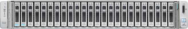
Our copy consists of four servers, each of which has 10 SSDs with 960 GB. There is a dedicated disk for caching write operations and storage of the service virtual machine. The solution itself is the fourth version. The first one is frankly raw (judging by the reviews), the second one is damp, the third one is already quite stable, and this one can be called a release after the end of beta testing for the general public. During the testing of the problems I did not see, everything works like a clock.
Initially, the platform could only work with the VMware ESXi hypervisor and supported a small number of nodes. Also, the deployment process did not always end successfully, I had to restart some steps, there were problems updating from old versions, the data in the GUI was not always displayed correctly (although I’m still not happy with displaying performance graphs), sometimes there were problems at the interface with virtualization .
Now all the children's sores have been fixed, HyperFlex can do both ESXi and Hyper-V, plus this is possible:
- Creating a stretched cluster.
- Creating a cluster for offices without using Fabric Interconnect, from two to four nodes (we buy only servers).
- Ability to work with external storage.
- Support for containers and Kubernetes.
- Creation of accessibility zones.
- Integration with VMware SRM, if the built-in functionality does not suit.
The architecture is not much different from the decisions of the main competitors; they did not begin to create a bicycle. It all works on the VMware or Hyper-V virtualization platform. Hardware hosted on Cisco UCS proprietary servers. There are those who hate the platform for the relative complexity of the initial setup, a lot of buttons, a non-trivial system of templates and dependencies, but there are those who have learned Zen, inspired by the idea and no longer want to work with other servers.
We will consider the solution specifically for VMware, because the solution was originally created for it and has more functionality, Hyper-V was added along the way to keep up with competitors and meet market expectations.
There is a cluster of servers full of disks. There are disks for data storage (SSD or HDD - to your taste and needs), there is one SSD disk for caching. When data is written to the datastore, data is saved on the caching layer (dedicated SSD-disk and service VM RAM). In parallel, the data block is sent to the nodes in the cluster (the number of nodes depends on the cluster replication factor). After confirmation from all nodes about the successful recording, the confirmation of the recording is sent to the hypervisor and then to the VM. Recorded data in the background is deduplicated, compressed and written to storage disks. At the same time, a large block is always written to storage disks and sequentially, which reduces the load on storage disks.
Deduplication and compression are always on and cannot be disabled. Data is read directly from storage disks or from the RAM cache. If a hybrid configuration is used, the read is also cached on the SSD.
Data is not tied to the current location of the virtual machine and is distributed evenly between the nodes. This approach allows you to equally load all drives and network interfaces. The obvious minus begs: we cannot minimize the read delay, since there is no guarantee of data availability locally. But I believe that this is an insignificant sacrifice in comparison with the pluses received. Moreover, network delays have reached such values that they practically do not affect the overall result.
For all the logic of the disk subsystem, a special service VM of the Cisco HyperFlex Data Platform controller is responsible, which is created on each storage node. In our service VM configuration, eight vCPUs and 72 GB of RAM were allocated, which is not so small. Let me remind you that the host itself has 28 physical cores and 512 GB of RAM.
The service VM has access to physical disks directly by forwarding the SAS controller to the VM. Communication with the hypervisor occurs through a special IOVisor module, which intercepts I / O operations, and using an agent that allows you to transfer commands to the hypervisor API. The agent is responsible for working with HyperFlex snapshots and clones.
In the hypervisor, disk resources are mounted as an NFS or SMB ball (depending on the type of hypervisor, guess which one). And under the hood, this is a distributed file system that allows you to add features of adult full-fledged storage systems: thin volume allocation, compression and deduplication, snapshots using Redirect-on-Write technology, synchronous / asynchronous replication.
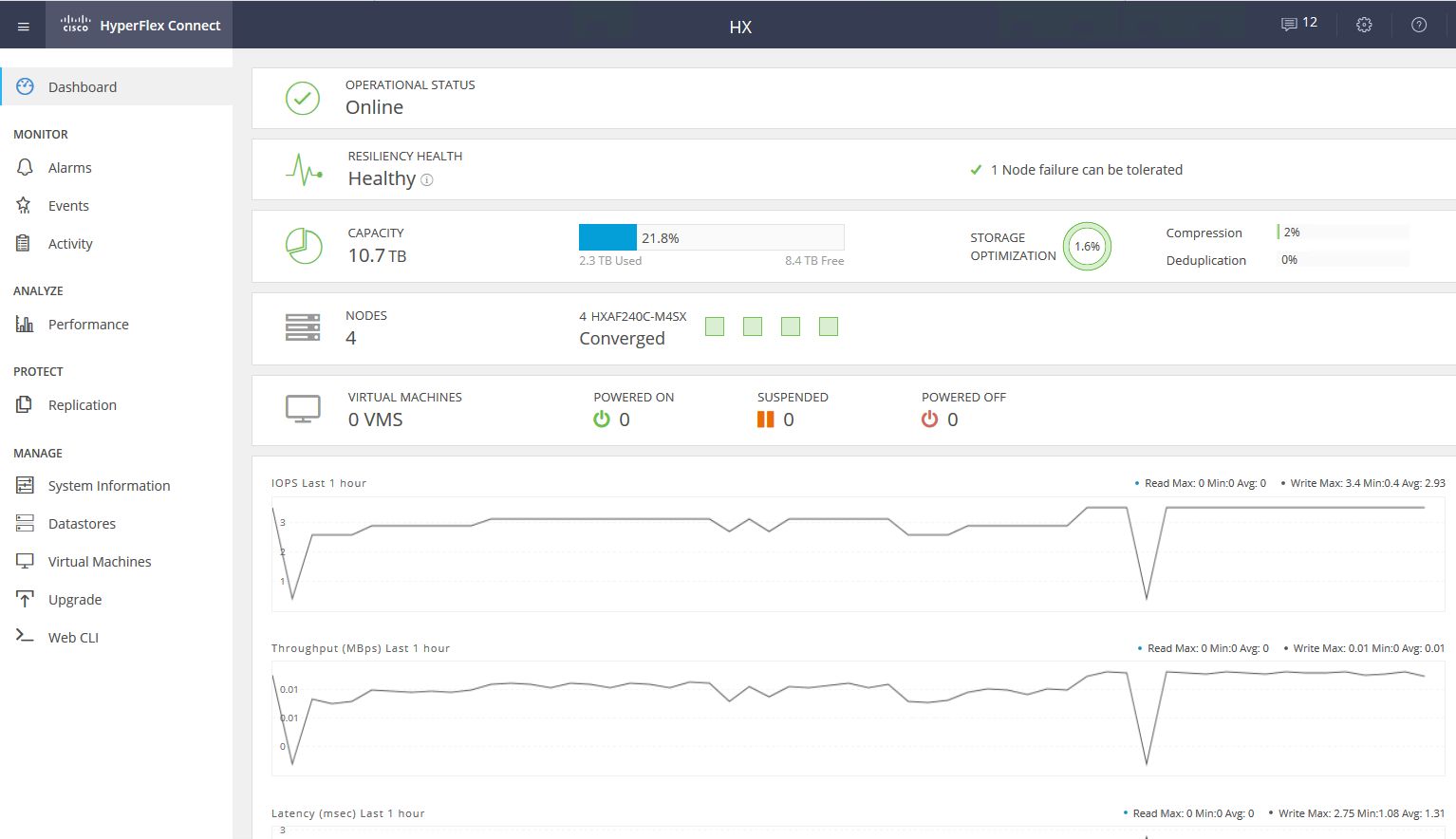
The service VM provides access to the WEB-management interface of the HyperFlex subsystem. There is integration with vCenter, and most of the daily tasks can be performed from it, but datastores, for example, are more convenient to cut from a separate webcam if you have already switched to a fast HTML5 interface, or use a full Flash client with full integration. In the service webcam, you can see the performance and detailed status of the system.
There is another kind of node in a cluster - computational nodes. It can be rack or blade servers without built-in drives. On these servers, you can run VMs whose data is stored on servers with disks. From the point of view of access to data, there is no difference between the types of nodes, because the architecture involves abstracting from the physical location of the data. The maximum ratio of compute nodes and storage nodes is 2: 1.
Using computational nodes increases flexibility when scaling cluster resources: we don’t have to buy nodes with disks if we only need CPU / RAM. In addition, we can add a blade basket and save on rack server space.
As a result, we have a hyperconverged platform with the following features:
- Up to 64 nodes in a cluster (up to 32 storage nodes).
- The minimum number of nodes in a cluster is three (two for an Edge cluster).
- Data redundancy mechanism: mirroring with replication factor 2 and 3.
- Metro cluster.
- Asynchronous VM replication to another HyperFlex cluster.
- Orchestration of switching VMs to a remote data center.
- Native snapshots using Redirect-on-Write technology.
- Up to 1 PB of usable space with replication factor 3 and without deduplication. We do not take into account replication factor 2, since this is not an option for serious selling.
Another huge plus is the ease of management and deployment. All the complexities of configuring UCS servers are handled by a specialized VM prepared by Cisco engineers.
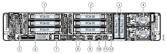
Testbed configuration:
- 2 x Cisco UCS Fabric Interconnect 6248UP as a management cluster and network components (48 ports operating in Ethernet 10G / FC 16G mode).
- Four Cisco UCS HXAF240 M4 Servers.
Server Features:
|
CPU |
2 x Intel ® Xeon ® E5-2690 v4 |
|
RAM |
16 x 32GB DDR4-2400-MHz RDIMM / PC4-19200 / dual rank / x4 / 1.2v |
|
Network |
UCSC-MLOM-CSC-02 (VIC 1227). 2 x 10G Ethernet |
|
Storage hba |
Cisco 12G Modular SAS Pass through Controller |
|
Storage disks |
1 x SSD Intel S3520 120 GB, 1 x SSD Samsung MZ-IES800D, 10 x SSD Samsung PM863a 960 GB |
- HXAF240c M5.
- One or two CPUs ranging from Intel Silver 4110 to Intel Platinum I8260Y. The second generation is available.
- 24 memory slots, slats from 16 GB RDIMM 2600 to 128 GB LRDIMM 2933.
- From 6 to 23 disks for data, one caching disk, one system and one boot disk.
Capacity drives
- HX-SD960G61X-EV 960GB 2.5 Inch Enterprise Value 6G SATA SSD (1X endurance) SAS 960 GB.
- HX-SD38T61X-EV 3.8TB 2.5 inch Enterprise Value 6G SATA SSD (1X endurance) SAS 3.8 TB.
- Caching drivers
- HX-NVMEXPB-I375 375GB 2.5 inch Intel Optane Drive, Extreme Perf & Endurance.
- HX-NVMEHW-H1600 * 1.6TB 2.5 inch Ent. Perf NVMe SSD (3X endurance) NVMe 1.6 TB.
- HX-SD400G12TX-EP 400GB 2.5 inch Ent. Perf 12G SAS SSD (10X endurance) SAS 400 GB.
- HX-SD800GBENK9 ** 800GB 2.5 inch Ent. Perf 12G SAS SED SSD (10X endurance) SAS 800 GB.
- HX-SD16T123X-EP 1.6TB 2.5 inch Enterprise performance 12G SAS SSD (3X endurance).
System / Log Drives
- HX-SD240GM1X-EV 240GB 2.5 inch Enterprise Value 6G SATA SSD (Requires upgrade).
Boot drivers
- HX-M2-240GB 240GB SATA M.2 SSD SATA 240 GB.
Connection to a network on 40G, 25G or 10G Ethernet ports.
As FI can be HX-FI-6332 (40G), HX-FI-6332-16UP (40G), HX-FI-6454 (40G / 100G).
Test itself
To test the disk subsystem, I used HCIBench 2.2.1. This is a free utility that allows you to automate the creation of load from multiple virtual machines. The load itself is generated by regular fio.
Our cluster consists of four nodes, replication factor 3, all Flash drives.
For testing, I created four datastores and eight virtual machines. For write tests, it is assumed that the caching disk is not full.
The test results are as follows:
|
100% Read 100% Random |
0% Read 100% Random | |||||||||
|
Block / Queue Depth |
128 |
256 |
512 |
1024 |
2048 |
128 |
256 |
512 |
1024 |
2048 |
|
4K |
0.59 ms 213804 IOPS |
0.84 ms 303540 IOPS |
1.36ms 374348 IOPS |
2.47 ms 414116 IOPS |
4.86ms 420180 IOPS |
2.22 ms 57408 IOPS |
3.09 ms 82744 IOPS |
5.02 ms 101824 IPOS |
8.75 ms 116912 IOPS |
17.2 ms 118592 IOPS |
|
8K |
0.67 ms 188416 IOPS |
0.93 ms 273280 IOPS |
1.7 ms 299932 IOPS |
2.72 ms 376.484 IOPS |
5.47 ms 373.176 IOPS |
3.1 ms 41148 IOPS |
4.7 ms 54396 IOPS |
7.09 ms 72192 IOPS |
12.77 ms 80-132 IOPS | |
|
16K |
0.77 ms 164116 IOPS |
1.12 ms 228328 IOPS |
1.9 ms 268140 IOPS |
3.96 ms 258480 IOPS |
3.8 ms 33640 IOPS |
6.97 ms 36696 IOPS |
11.35 ms 45060 IOPS | |||
|
32K |
1.07 ms 119292 IOPS |
1.79 ms 142888 IOPS |
3.56 ms 143760 IOPS |
7.17 ms 17810 IOPS |
11.96 ms 21396 IOPS | |||||
|
64K |
1.84 ms 69440 IOPS |
3.6 ms 71008 IOPS |
7.26 ms 70404 IOPS |
11.37 ms 11248 IOPS | ||||||
Bold values are indicated, after which there is no increase in productivity, sometimes even degradation is visible. Due to the fact that we rest on the network performance / controllers / drives.
- Sequential read 4432 MB / s.
- Sequential write 804 MB / s.
- If one controller fails (virtual machine or host failure), the performance drawdown is two times.
- If the storage drive fails, the drawdown is 1/3. Rebild disk takes 5% of the resources of each controller.
On a small block, we run into the performance of the controller (virtual machine), its CPU is 100% loaded, while increasing the block we run into port bandwidth. 10 Gbps is not enough to unlock the potential of the AllFlash system. Unfortunately, the parameters of the provided demo stand do not allow checking the work at 40 Gb / s.
In my impression of the tests and the study of architecture, due to the algorithm that places data between all the hosts, we get scalable predictable performance, but this is also a limitation when reading, since it would be possible to squeeze more from local disks and more, here to save a more productive network, for example, 40 Gbps FIs are available.
Also, one disk for caching and deduplication may be a limitation; in fact, in this stand we can write on four SSD disks. It would be great to be able to increase the number of cached disks and see the difference.
Real use
To organize a backup data center, you can use two approaches (we do not consider placing backup on a remote site):
- Active Passive All applications are hosted in the main data center. Replication is synchronous or asynchronous. In the event of a fall in the main data center, we need to activate the backup one. You can do this manually / scripts / orchestration applications. Here we get an RPO commensurate with the replication frequency, and the RTO depends on the reaction and skills of the administrator and the quality of the development / debugging of the switching plan.
- Active Active In this case, only synchronous replication is present, the availability of data centers is determined by a quorum / arbiter, placed strictly on the third site. RPO = 0, and RTO can reach 0 (if the application allows) or equal to the time to fail over a node in a virtualization cluster. At the virtualization level, a stretched (Metro) cluster is created that requires Active-Active storage.
Usually, we see clients with already implemented architecture with classic storage in the main data center, so we design another one for replication. As I mentioned, Cisco HyperFlex offers asynchronous replication and the creation of an extended virtualization cluster. At the same time, we don’t need a dedicated Midrange or higher storage system with expensive replication and Active-Active data access features on two storage systems.
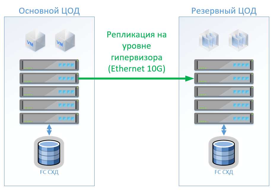
Scenario 1: We have primary and backup data centers, a virtualization platform on VMware vSphere. All productive systems are located mainly in the data center, and virtual machine replication is performed at the hypervisor level, this will allow not to keep the VMs turned on in the backup data center. We replicate databases and special applications with built-in tools and keep VMs turned on. If the main data center fails, we start the system in the backup data center. We believe that we have about 100 virtual machines. While the main data center is operating, test environments and other systems can be launched in the backup data center, which can be disabled if the main data center is switched. It is also possible that we use two-way replication. From the point of view of equipment, nothing will change.
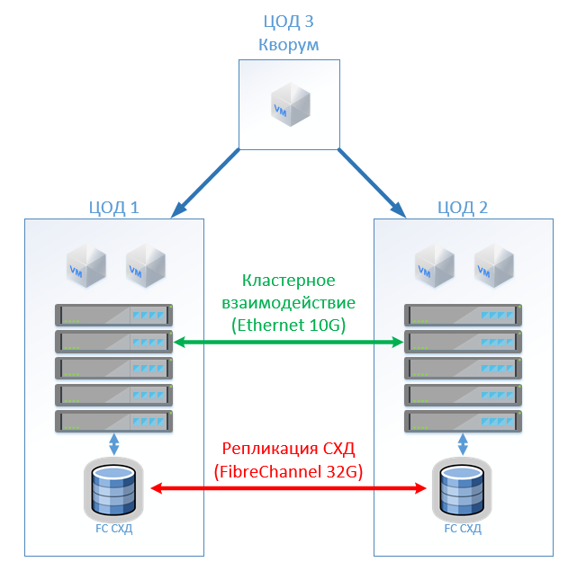
In the case of the classical architecture, we will put in each data center a hybrid storage system with access via FibreChannel, tearing, deduplication and compression (but not online), 8 servers per site, 2 FibreChannel switches and Ethernet 10G. For replication and switching control in a classical architecture, we can use VMware tools (Replication + SRM) or third-party tools that will be slightly cheaper and sometimes more convenient.
The figure shows a diagram.
If you use Cisco HyperFlex, you get the following architecture:
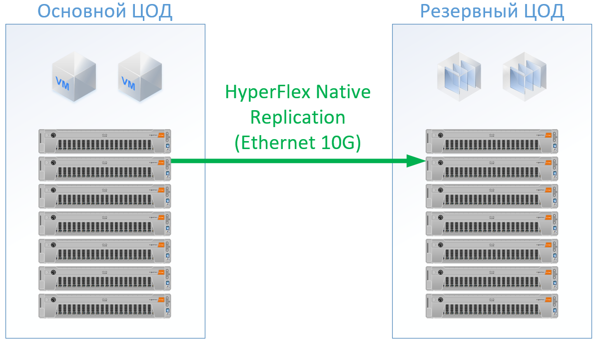
For HyperFlex, I used servers with large CPU / RAM resources, as part of the resources will go to the HyperFlex controller’s VM, I’ve even reloaded the HyperFlex configuration on the CPU and memory a bit so as not to play alongside Cisco and guarantee resources for the rest of the VMs. But we can refuse from FibreChannel switches, and we do not need Ethernet ports for each server, local traffic is switched inside FI.
The result is the following configuration for each data center:
|
Servers |
8 x 1U Server (384 GB RAM, 2 x Intel Gold 6132, FC HBA) |
8 x HX240C-M5L (512 GB RAM, 2 x Intel Gold 6150, 3.2 GB SSD, 10 x 6 TB NL-SAS) |
|
SHD |
Hybrid Storage with FC Front-End (20TB SSD, 130 TB NL-SAS) |
- |
|
LAN |
2 x Ethernet switch 10G 12 ports |
- |
|
San |
2 x FC switch 32 / 16Gb 24 ports |
2 x Cisco UCS FI 6332 |
|
Licenses |
VMware Ent Plus VM replication and / or orchestration |
VMware Ent Plus |
For Hyperflex, I did not pledge replication software licenses, since this is available out of the box with us.
For classical architecture, I took a vendor who has established himself as a quality and inexpensive manufacturer. For both options I used a standard for a specific solution skid, at the output I got real prices.
The solution on Cisco HyperFlex was 13% cheaper.
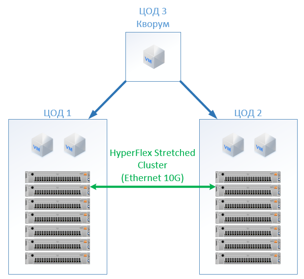
Scenario 2: creating two active data centers. In this scenario, we are designing an extended cluster on VMware.
The classical architecture consists of virtualization servers, SAN (FC protocol) and two storage systems that can read and write on the one stretched between them. On each SHD we lay a useful capacity for the lock.
At HyperFlex, we simply create a Stretch Cluster with the same number of nodes on both sites. In this case, the replication factor 2 + 2 is used.
The following configuration has turned out:
|
Classic architecture |
Hyperflex | |
|
Servers |
16 x 1U Server (384 GB RAM, 2 x Intel Gold 6132, FC HBA, 2 x 10G NIC) |
16 x HX240C-M5L (512 GB RAM, 2 x Intel Gold 6132, 1.6 TB NVMe, 12 x 3.8 TB SSD, VIC 1387) |
|
SHD |
2 x AllFlash Storage (150 TB SSD) |
- |
|
LAN |
4 x Ethernet switch 10G 24 ports |
- |
|
San |
4 x FC switch 32 / 16Gb 24 ports |
4 x Cisco UCS FI 6332 |
|
Licenses |
VMware Ent Plus |
VMware Ent Plus |
In all calculations, I did not take into account the network infrastructure, data center costs, etc.: they will be the same for the classical architecture and for the HyperFlex solution.
At cost, HyperFlex is 5% more expensive. Here it is worth noting that for the CPU / RAM resources, I got a bias for Cisco, because in the configuration it filled the channels of the memory controllers evenly. The cost is slightly higher, but not by an order of magnitude, which clearly indicates that hyperconvergence is not necessarily a "toy for the rich", but can compete with the standard approach to building a data center. It may also be interesting to those who already have a Cisco UCS server and the corresponding infrastructure for them.
The advantages include the absence of SAN and storage administration costs, online compression and deduplication, a single entry point for support (virtualization, servers, they are storage systems), space saving (but not in all scenarios), and simplification of operation.
As for support, here you get it from one vendor - Cisco. Judging by the experience with Cisco UCS servers, I like it, I didn’t have to open it on HyperFlex, everything worked like that. Engineers respond promptly and can solve not only typical problems, but also complex border cases. Sometimes I turn to them with questions: “Is it possible to do so, fasten it?” Or “I have configured something here, and it does not want to work. Help! ”- they will patiently find the necessary guide there and point out the correct actions, answer:“ We solve only hardware problems ”they will not.
References
- Specs
- Virtual data center
- Data center in a desk drawer
- My mail is StGeneralov@croc.ru