And so I want to introduce you to a designer the size of a plastic bank card, which was designed to familiarize children with simple schemes, but in a rather unusual way. The idea was to make Connoisseur level simplicity, but on breadboards.
To make a constructor, you will need to download three PDF files from the link .
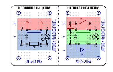
Then print and paste on the thick paper the first of them: Map-scheme.
Then you need to poke holes with a needle in it in the designated places, cut it into two halves and fix it with the button-nails on the breadboard.
The other two files are the front and back of the explanation cards with tasks. They must be printed on A4 format, glued together and cut.
In addition to cards, you will need to find in your bins or buy:
- Mini breadboard 10x17 for assembly without soldering;
- A set of resistors (220 Ohm, 1 KOhm, 10 KOhm, but other close denominations are possible and preferably with thin legs);
- Diode 1A;
- LED (2-2.5V) of any color;
- Mini incandescent light bulb (3 V);
- Jumpers for a breadboard 1 cm wide;
- Two AA batteries;
- Three neodymium magnets with a diameter of 5 mm or a battery compartment for 2 batteries;
- Four wire probes connecting for prototyping boards;
- Four buttons-cloves;
- Examples of conductors and dielectrics.
The principle is simple - all cards are numbered in numbers and letters. The child starts with A1, then goes to B1, etc., then to a new digit. The letter denotes a segment on the chart map, a digit indicates the chart card number.
On one side of the card is given a theory of the component being studied and assembly instructions, on the other side is a graphic image, an interesting fact and a question that the child must give an answer to.

The circuit is assembled using a circuit map on a breadboard and tested for operability.
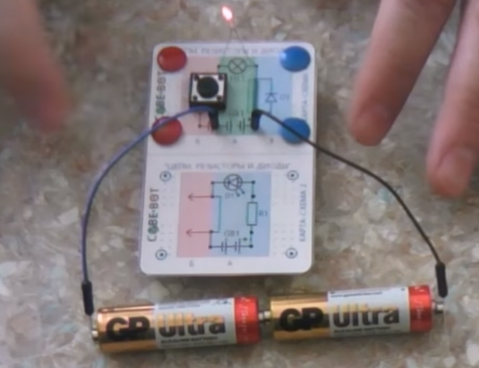
The designer, although tiny, but shows how the simplest electrical circuit is arranged allows you to "touch" the real radio components.
You can see more details about the designer in the attached video:
All files are free and free to download, you can use them as you wish, but I would be grateful if you mention my project SIMPLEROBOT | SIMPLY.