Application MATLAB / Simulink with equipment manufactured by InSys JSC
An important practical task is the use of Matlab / Simulink with real equipment that will allow you to receive a signal from the real world. This is very useful for debugging algorithms. This paper presents the technology for connecting ADC devices manufactured by InSys JSC to Simulink. A DLL is used to connect, which is visible in Simulink as a sm_adc component. A separate console program is used to work with the equipment. Communication with the DLL is through shared memory. According to this technology, any ADCs on any supporting modules of InSys JSC can be connected. The paper presents a system from an A7_DAC generator and an FMC128E / FM412x500M acquisition module.
This work was demonstrated at the conference "Technologies for the development and debugging of complex technical systems" on March 27-28, 2018.
Formulation of the problem
It requires the development of a system of a signal generator and an ADC that will generate a signal with the given parameters and digitize it. The received data should be transferred to Simulink for processing.
Equipment
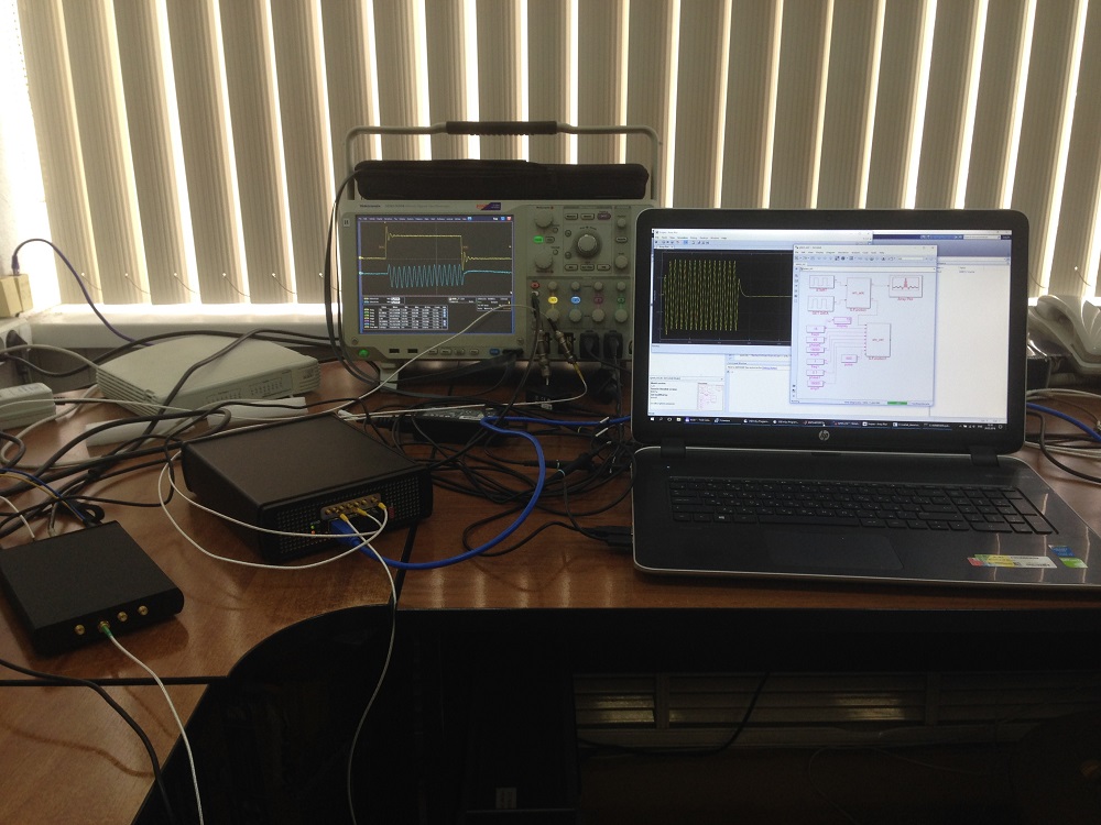
For work, a stand was assembled from the ADC module and the generator. As the ADC, the FM412x500M submodule is used in which there are four ADC channels with a sampling frequency of 500 MHz. The submodule is installed on the FMC128E carrier module in which there is an Artix 7 FPGA and a USB 3.0 interface. Both devices are connected to a laptop running Simulink. To monitor performance, of course, an oscilloscope is used.
Appearance of the stand:
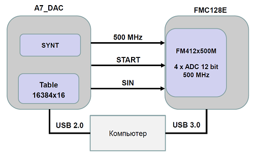
Structural diagram of the stand:
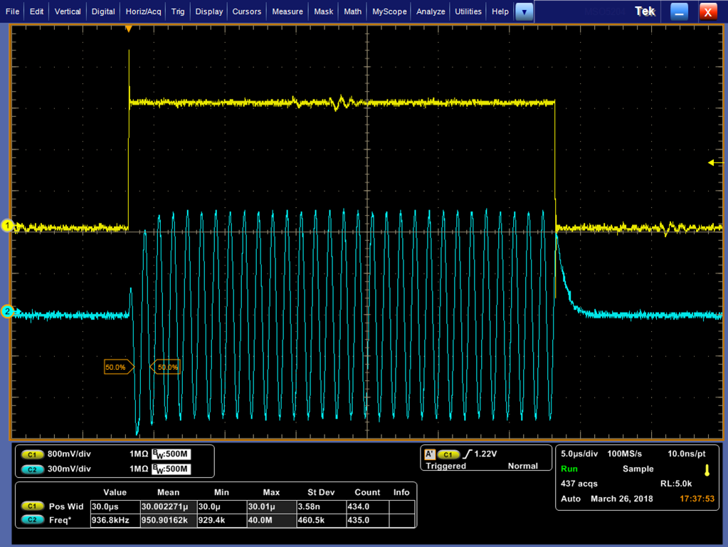
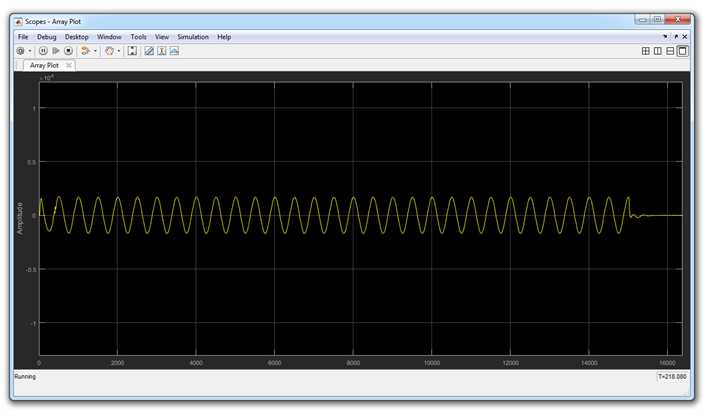
Signal generated:
The algorithm of the stand:
This is a classic one-time collection mode. Its peculiarity is just singleness. The equipment along the signal front collects a given data array. The phase of data collection occurs in the "hard real time" mode, but the processing is how to get it. The collection rate is determined by the number of selected channels and sampling rate. For four ADC channels and a sampling frequency of 500 MHz, the data rate is 4 GB / s. At this speed, data can be written to the SODIMM of the FMC128E module. That is, a 4 GB sample can be saved.
Further, the data should be transferred to the computer. The FMC128E module is connected to the computer via the USB 3.0 interface. The data transfer rate is 300 MB / s.
Simulink takes an array of data and passes it on for further processing. The time for this processing is already determined by the complexity of the model. In this example, the array is simply displayed on the oscilloscope panel.
At some point, Simulink decides that it is necessary to carry out the next cycle and everything repeats. Again USB commands are sent to prepare the ADC, to start the generator and to collect data.
This mode is very convenient for debugging hardware and algorithms. You can not rush anywhere. Collect an array of data. You can calmly look at it, burn it to a disc, drink coffee. But when everything is worked out, then it is already possible to switch to a continuous collection mode.
DLL connection
Matlab allows you to connect functions implemented in external DLLs. Simulink also has the ability to connect external DLLs, while it adds some requirements. Inside Simulink, the external DLL looks like an S-Function block.
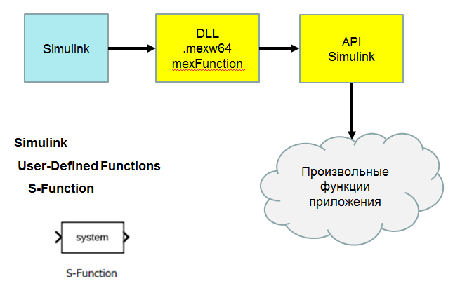
MATLAB provides a huge number of examples, including the creation of external DLLs. However, the method that MATLAB offers is not very convenient. There is an OpenSource easyLink project. This project has developed a class library for connecting to Simulink.
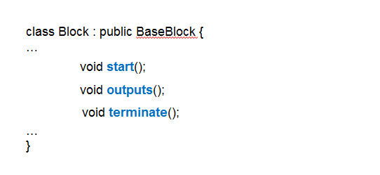
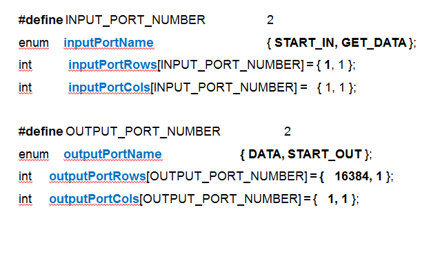
To create a component, you need to create a class derived from BaseBlock and declare ports:
DLL connection problems
External DLLs allow a lot, but there are a number of problems when working with them. The most significant for me personally are the following:
When debugging a program, step-by-step debugging is required. In the case of a DLL, it is possible to connect to a DLL already loaded into memory, assign a breakpoint there, and conduct a debugging session. But it is necessary to catch the moment of loading the DLL through Simulink, somehow delay the start of work. All this can be done, but inconvenient.
In the process, I really want to see the debug output that is formed as a standard stdout stream. In the case of the DLL, this thread can be intercepted somehow, but I did not succeed.
And finally, the most important inconvenience is the need to exit MATLAB when recompiling the DLL. Otherwise, you just cannot write a new file. And exit and subsequent launch of MATLAB takes a lot of time.
To solve these problems, there is a classic way to build complex software systems. This is the interaction between programs through shared memory.
Shared Memory Connection
Modern operating systems, both Windows and Linux, allow you to organize common areas of memory. This allows you to create reliable programs. For example, one program may contain a graphical interface and interact with the operator, and another program may interact with the equipment. In this case, the freezing of the program that interacts with the equipment will not lead to the freezing of the program of interaction with the operator. In the case of Simulink, this approach also provides some advantages. The program for working with the equipment will be launched once, it will prepare the equipment and will wait for the command through shared memory. The DLL will load every time you run Simulink on simulation. Since the DLL does not work directly with the hardware, this launch will be quick.
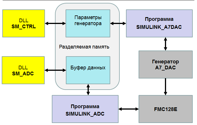
Two programs and two DLLs have been developed for this stand:
The block diagram is presented in the figure below:
The simulink_adc program is based on the Bardy library. This program allows you to work with any ADC manufactured by InSys JSC. Tuning to a specific ADC and carrier module is done through initialization files.
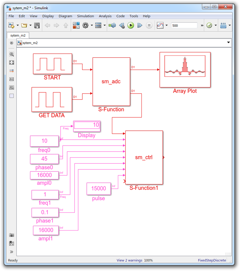
Scheme view in Simulink
And finally, what it looks like inside Simulink:
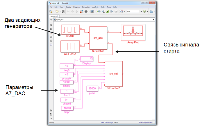
Everything looks as it is in Simulink. One unit for ADC control. The second block to control the generator. A number of parameters are available to control the generator. For the ADC, everything is through the initialization file. If necessary, a number of ADC parameters can also be displayed at the block level.
Note the two master oscillators. In terms of model time, they specify the start time and the moment of data collection. These points are very important. They actually set the connection between the model and the real world. The start signal enters the ADC block, it is processed in the DLL. Through shared memory, he enters the ADC program. Then it is converted into a sequence of write commands to the registers, which via USB enter the FPGA. And inside the FPGA, the search front edge of the start signal is cocked. And only after the machine is cocked in the opposite direction, the confirmation goes through the same chain. When the confirmation reaches Simulink, the start_out signal will appear at the output of the sm_adc block, which will be passed to the sm_ctrl block. And it will be all the same moment of model time. In the sm_ctrl block, along the same chain, the signal will be transmitted to the FPGA of the generator and it will form a signal. The ADC will capture this signal in its memory. A data acquisition signal will be generated from the second master oscillator. In the same way, the data gets into Simulink and goes to the data output of the sm_adc block. At the moment, a block of 16384 counts is being returned. The received block is displayed on the oscilloscope.
results
Work through shared memory has been shown to be effective. The ADC management program allows you to work with any of our ADCs. At the same time, there remains a convenient way to configure parameters through the configuration file. The program is designed as a console application, while all the debug output is visible. There is an indication of operability. The SM_CTRL component allows you to connect various external applications for controlling equipment. Debugging the ADC control program does not cause any difficulties. This is a common program where you can set breakpoints and debug. Using the same technology, other programs for interaction between Matlab / Simulink and the outside world can be developed.
The work is published on the site hub.exponenta.ru ;
References:
This work was demonstrated at the conference "Technologies for the development and debugging of complex technical systems" on March 27-28, 2018.
Formulation of the problem
It requires the development of a system of a signal generator and an ADC that will generate a signal with the given parameters and digitize it. The received data should be transferred to Simulink for processing.
Equipment
For work, a stand was assembled from the ADC module and the generator. As the ADC, the FM412x500M submodule is used in which there are four ADC channels with a sampling frequency of 500 MHz. The submodule is installed on the FMC128E carrier module in which there is an Artix 7 FPGA and a USB 3.0 interface. Both devices are connected to a laptop running Simulink. To monitor performance, of course, an oscilloscope is used.
Appearance of the stand:
Structural diagram of the stand:
Signal generated:
The algorithm of the stand:
- Simulink prepares to launch the ADC and generator
- Simulink instructs the generator to start
- The generator forms a strobe (yellow signal) and the actual signal (blue)
- ADC on the front of the gate starts collecting data
- The ADC collects the array and passes it to Simulink
- Simulink displays the received signal from the ADC
This is a classic one-time collection mode. Its peculiarity is just singleness. The equipment along the signal front collects a given data array. The phase of data collection occurs in the "hard real time" mode, but the processing is how to get it. The collection rate is determined by the number of selected channels and sampling rate. For four ADC channels and a sampling frequency of 500 MHz, the data rate is 4 GB / s. At this speed, data can be written to the SODIMM of the FMC128E module. That is, a 4 GB sample can be saved.
Further, the data should be transferred to the computer. The FMC128E module is connected to the computer via the USB 3.0 interface. The data transfer rate is 300 MB / s.
Simulink takes an array of data and passes it on for further processing. The time for this processing is already determined by the complexity of the model. In this example, the array is simply displayed on the oscilloscope panel.
At some point, Simulink decides that it is necessary to carry out the next cycle and everything repeats. Again USB commands are sent to prepare the ADC, to start the generator and to collect data.
This mode is very convenient for debugging hardware and algorithms. You can not rush anywhere. Collect an array of data. You can calmly look at it, burn it to a disc, drink coffee. But when everything is worked out, then it is already possible to switch to a continuous collection mode.
DLL connection
Matlab allows you to connect functions implemented in external DLLs. Simulink also has the ability to connect external DLLs, while it adds some requirements. Inside Simulink, the external DLL looks like an S-Function block.
MATLAB provides a huge number of examples, including the creation of external DLLs. However, the method that MATLAB offers is not very convenient. There is an OpenSource easyLink project. This project has developed a class library for connecting to Simulink.
To create a component, you need to create a class derived from BaseBlock and declare ports:
DLL connection problems
External DLLs allow a lot, but there are a number of problems when working with them. The most significant for me personally are the following:
- DLL debugging is difficult
- Inconvenient to see printf () output
- Recompiling a DLL requires exit from MATLAB
When debugging a program, step-by-step debugging is required. In the case of a DLL, it is possible to connect to a DLL already loaded into memory, assign a breakpoint there, and conduct a debugging session. But it is necessary to catch the moment of loading the DLL through Simulink, somehow delay the start of work. All this can be done, but inconvenient.
In the process, I really want to see the debug output that is formed as a standard stdout stream. In the case of the DLL, this thread can be intercepted somehow, but I did not succeed.
And finally, the most important inconvenience is the need to exit MATLAB when recompiling the DLL. Otherwise, you just cannot write a new file. And exit and subsequent launch of MATLAB takes a lot of time.
To solve these problems, there is a classic way to build complex software systems. This is the interaction between programs through shared memory.
Shared Memory Connection
Modern operating systems, both Windows and Linux, allow you to organize common areas of memory. This allows you to create reliable programs. For example, one program may contain a graphical interface and interact with the operator, and another program may interact with the equipment. In this case, the freezing of the program that interacts with the equipment will not lead to the freezing of the program of interaction with the operator. In the case of Simulink, this approach also provides some advantages. The program for working with the equipment will be launched once, it will prepare the equipment and will wait for the command through shared memory. The DLL will load every time you run Simulink on simulation. Since the DLL does not work directly with the hardware, this launch will be quick.
Two programs and two DLLs have been developed for this stand:
- simulink_a7dac - generator control program
- simulink_adc - ADC control program
- sm_ctrl - generator control DLL
- sm_adc - ADC control DLL
The block diagram is presented in the figure below:
The simulink_adc program is based on the Bardy library. This program allows you to work with any ADC manufactured by InSys JSC. Tuning to a specific ADC and carrier module is done through initialization files.
Scheme view in Simulink
And finally, what it looks like inside Simulink:
Everything looks as it is in Simulink. One unit for ADC control. The second block to control the generator. A number of parameters are available to control the generator. For the ADC, everything is through the initialization file. If necessary, a number of ADC parameters can also be displayed at the block level.
Note the two master oscillators. In terms of model time, they specify the start time and the moment of data collection. These points are very important. They actually set the connection between the model and the real world. The start signal enters the ADC block, it is processed in the DLL. Through shared memory, he enters the ADC program. Then it is converted into a sequence of write commands to the registers, which via USB enter the FPGA. And inside the FPGA, the search front edge of the start signal is cocked. And only after the machine is cocked in the opposite direction, the confirmation goes through the same chain. When the confirmation reaches Simulink, the start_out signal will appear at the output of the sm_adc block, which will be passed to the sm_ctrl block. And it will be all the same moment of model time. In the sm_ctrl block, along the same chain, the signal will be transmitted to the FPGA of the generator and it will form a signal. The ADC will capture this signal in its memory. A data acquisition signal will be generated from the second master oscillator. In the same way, the data gets into Simulink and goes to the data output of the sm_adc block. At the moment, a block of 16384 counts is being returned. The received block is displayed on the oscilloscope.
results
Work through shared memory has been shown to be effective. The ADC management program allows you to work with any of our ADCs. At the same time, there remains a convenient way to configure parameters through the configuration file. The program is designed as a console application, while all the debug output is visible. There is an indication of operability. The SM_CTRL component allows you to connect various external applications for controlling equipment. Debugging the ADC control program does not cause any difficulties. This is a common program where you can set breakpoints and debug. Using the same technology, other programs for interaction between Matlab / Simulink and the outside world can be developed.
The work is published on the site hub.exponenta.ru ;
References:
All Articles