Fake DS18B20 waterproof: what to do?
Good day! This article reflects the problem of fake sensors, the limitations of existing devices using these sensors, and the solution to this problem.

Source: ali-trends.ru
Before me, fake sensors were also written here . Characteristic differences of fake sensors from the original:
Unfortunately, I do not have an oscilloscope, and the Galileosky BaseBlock Lite GPS tracker acted as a test bench.
Sensors were purchased from various sellers, and only one batch earned on parasitic food. Only 5 lots of 50 pieces were purchased.
The rest did not earn parasitic food at all. The terminal does not provide external power for the sensor, and the installation of the system on the car must be simplified as much as possible.
So, the sensors were purchased, but only one batch earned correctly, and a decent time would have taken up the proceedings and ordering a new batch, and would have led to cost overruns. Therefore, the problem had to be solved on their own.
Since only a two-wire circuit is used, it is necessary to organize the power supply of the sensor from the signal wire, that is, to organize spurious power. I organized parasitic food according to the following scheme:
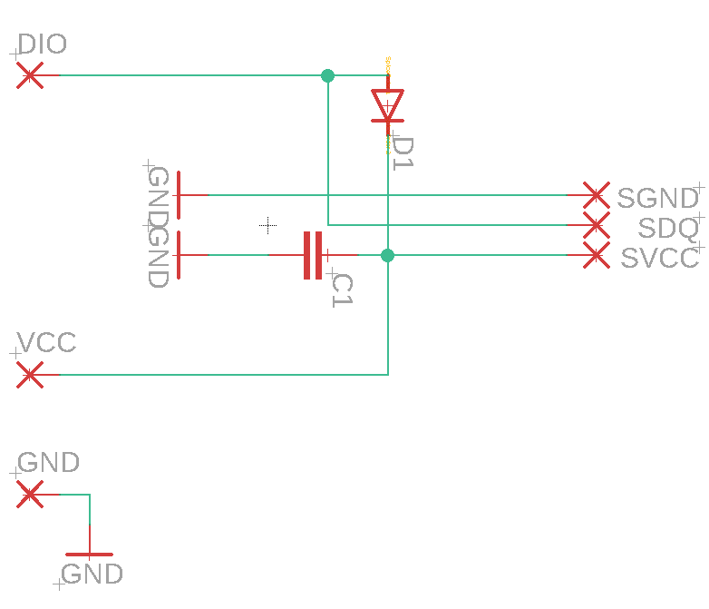
In this scheme, the operation of parasitic power is improved, but, at the same time, the ability to connect external power is left. At the same time, the connection scheme changes slightly: when connecting to stray power, the Vcc wire is not used .
After assembling the circuit by hinged mounting, the sensor was detected by the terminal with a capacitor capacity of 1 μF. For mass implementation, panel boards with spurious power boards were designed and ordered:

An interesting point: manufacturers can use hot melt adhesive or silicone to seal the sensor. In the first case, you can heat the sleeve, remove the sensor, introduce the board, return it to the sleeve and fill it with hot glue. In the second, this will not work out anymore, and I had to solder the board close to the sensor, pour hot glue and put on heat shrink, as a result, it looks like this:

Here I would like to encourage device manufacturers to take this moment into account in their products, and sellers to check sensors before selling or not to deal with the supplier at all if they supply counterfeit sensors and users to cover this topic in comments, letters or appeals.
Source: ali-trends.ru
Before me, fake sensors were also written here . Characteristic differences of fake sensors from the original:
- The sensor, even connected in close proximity, responds in a mode of parasitic power uncertainly, through time.
- In the parasitic power mode, a high level is restored for too long (you can measure it with a microcontroller or watch an oscillogram)
- current consumption is much higher than several microamps (GND and VCC minus, DQ through microammeter +5 volts)
- After the enumeration procedure (0xF0), the sensors do not respond to the scratchpad read command (0xBE)
- The temperature read from the scratchpad after power is supplied without a measurement command differs from 85.0 degrees.
- The values in the scratchpad at positions 5 and 7 do not correspond to 0xFF and 0x10
- The temperature values (in the first two positions of the scratchpad) read after the first switch-on of the de-energized sensor without a previously issued measurement command return the previous value, not 50 05 (85.0 degrees).
Unfortunately, I do not have an oscilloscope, and the Galileosky BaseBlock Lite GPS tracker acted as a test bench.
Sensors were purchased from various sellers, and only one batch earned on parasitic food. Only 5 lots of 50 pieces were purchased.
The rest did not earn parasitic food at all. The terminal does not provide external power for the sensor, and the installation of the system on the car must be simplified as much as possible.
Solution
So, the sensors were purchased, but only one batch earned correctly, and a decent time would have taken up the proceedings and ordering a new batch, and would have led to cost overruns. Therefore, the problem had to be solved on their own.
Since only a two-wire circuit is used, it is necessary to organize the power supply of the sensor from the signal wire, that is, to organize spurious power. I organized parasitic food according to the following scheme:
In this scheme, the operation of parasitic power is improved, but, at the same time, the ability to connect external power is left. At the same time, the connection scheme changes slightly: when connecting to stray power, the Vcc wire is not used .
After assembling the circuit by hinged mounting, the sensor was detected by the terminal with a capacitor capacity of 1 μF. For mass implementation, panel boards with spurious power boards were designed and ordered:
An interesting point: manufacturers can use hot melt adhesive or silicone to seal the sensor. In the first case, you can heat the sleeve, remove the sensor, introduce the board, return it to the sleeve and fill it with hot glue. In the second, this will not work out anymore, and I had to solder the board close to the sensor, pour hot glue and put on heat shrink, as a result, it looks like this:
Conclusion
Here I would like to encourage device manufacturers to take this moment into account in their products, and sellers to check sensors before selling or not to deal with the supplier at all if they supply counterfeit sensors and users to cover this topic in comments, letters or appeals.
All Articles