Hyperconverged solution AERODISK vAIR. Basis - ARDFS File System
Hello, readers of Habr. With this article, we open a cycle that will talk about the hyperconverged system AERODISK vAIR that we developed. Initially, we wanted the first article to tell everything about everything, but the system is quite complex, so we will eat an elephant in parts.
Let's start the story with the history of the system, go deeper into the ARDFS file system, which is the foundation of vAIR, and also talk a bit about positioning this solution on the Russian market.
In future articles, we will talk more about different architectural components (cluster, hypervisor, load balancer, monitoring system, etc.), the configuration process, we will raise licensing issues, separately show crash tests and, of course, write about load testing and sizing. We will also devote a separate article to the community version of vAIR.
Is aerodisk a bit of a storage story? Or why did we even start hyperconverging?
Initially, the idea to create our own hyperconvergent came to us somewhere around the 2010th year. Then there was no Aerodisk or similar solutions (commercial boxed hyperconverged systems) on the market. Our task was as follows: from a set of servers with local disks connected by an interconnect via Ethernet, we had to make extended storage and run virtual machines and a program network in the same place. All this was required to be implemented without storage systems (because there was simply no money for storage and its bundling, and we had not yet invented our own storage system).
We tried many open source solutions, and yet we solved this problem, but the solution was very complicated, and it was difficult to repeat. In addition, this decision was from the category of “Works? Don’t touch! ” Therefore, having solved that problem, we did not further develop the idea of turning the result of our work into a full-fledged product.
After that incident, we moved away from this idea, but we still had a feeling that this task was completely solvable, and the benefits of such a solution were more than obvious. Subsequently, the HCI products of foreign companies that were released only confirmed this feeling.
Therefore, in the middle of 2016, we returned to this task as part of the creation of a full-fledged product. Then we did not have any relations with investors yet, so we had to buy a development stand for our not very big money. Having typed on Avito BU-shyh servers and switches, we set to work.

The main initial task was to create your own, albeit simple, but your own file system, which would be able to automatically and evenly distribute data in the form of virtual blocks on the nth number of cluster nodes that are interconnected via Ethernet. In this case, the FS should be well and easily scaled and independent of adjacent systems, i.e. be alienated from vAIR in the form of "just storage."

VAIR First Concept
We intentionally refused to use ready-made open source solutions for organizing extended storage (ceph, gluster, luster and the like) in favor of our development, since we already had a lot of project experience with them. Of course, these solutions themselves are wonderful, and before we worked on Aerodisk, we implemented more than one integration project with them. But it’s one thing to realize the specific task of one customer, to train staff and, possibly, buy support for a large vendor, and it’s quite another thing to create an easily replicated product that will be used for different tasks, which we, as a vendor, may even know ourselves we will not. For the second purpose, the existing open source products did not suit us, so we decided to saw the distributed file system ourselves.
Two years later, several developers (who combined work on vAIR with work on the classic Storage Engine) achieved a certain result.
By 2018, we had written the simplest file system and supplemented it with the necessary binding. The system integrated physical (local) disks from different servers into one flat pool via an internal interconnect and “cut” them into virtual blocks, then block devices with varying degrees of fault tolerance were created from virtual blocks on which virtual KVM hypervisors were created and executed cars.
We did not bother with the name of the file system and succinctly called it ARDFS (guess how it decrypts))
This prototype looked good (not visually, of course, there was no visual design then) and showed good results in performance and scaling. After the first real result, we set the course for this project by organizing a fully-fledged development environment and a separate team that was engaged only in vAIR.
Just at that time, the general architecture of the solution had matured, which until now had not undergone major changes.
Diving into the ARDFS file system
ARDFS is the foundation of vAIR, which provides distributed failover storage of the entire cluster. One (but not the only) distinguishing feature of ARDFS is that it does not use any additional dedicated servers for meta and management. This was originally conceived to simplify the configuration of the solution and for its reliability.
Storage structure
Within all cluster nodes, ARDFS organizes a logical pool from all available disk space. It is important to understand that a pool is not yet data and not formatted space, but simply markup, i.e. any nodes with vAIR installed when added to the cluster are automatically added to the shared ARDFS pool and disk resources automatically become shared across the entire cluster (and available for future data storage). This approach allows you to add and remove nodes on the fly without any serious impact on an already running system. Those. the system is very easy to scale with "bricks", adding or removing nodes in the cluster if necessary.
Virtual disks (storage objects for virtual machines) are added on top of the ARDFS pool, which are built from virtual blocks of 4 megabytes in size. Virtual disks store data directly. At the virtual disk level, a fault tolerance scheme is also defined.
As you might have guessed, for the fault tolerance of the disk subsystem, we do not use the concept of RAID (Redundant array of independent Disks), but use RAIN (Redundant array of independent Nodes). Those. fault tolerance is measured, automated and managed based on nodes, not disks. Disks, of course, are also a storage object, they, like everything else, are monitored, you can perform all standard operations with them, including building local hardware RAID, but the cluster operates with nodes.
In a situation where you really want RAID (for example, a scenario that supports multiple failures on small clusters), nothing prevents you from using local RAID controllers, and doing stretched storage and a RAIN architecture on top. This scenario is quite lively and is supported by us, so we will talk about it in an article about typical scenarios for using vAIR.
Storage Failover Schemes
There may be two vAIR virtual disk resiliency schemes:
1) Replication factor or just replication - this method of fault tolerance is simple “like a stick and a rope”. Synchronous replication between nodes with a factor of 2 (2 copies per cluster) or 3 (3 copies, respectively) is performed. RF-2 allows a virtual disk to withstand a failure of one node in a cluster, but “eats” half of the usable volume, and RF-3 will withstand a failure of 2 nodes in a cluster, but it will reserve 2/3 of usable volume for its needs. This scheme is very similar to RAID-1, that is, a virtual disk configured in RF-2 is resistant to failure of any one node of the cluster. In this case, the data will be all right and even I / O will not stop. When a fallen node returns to operation, automatic data recovery / synchronization will begin.
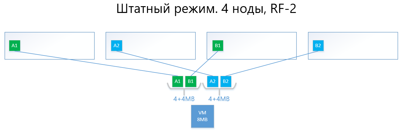
The following are examples of the distribution of RF-2 and RF-3 data in normal mode and in a failure situation.
We have a virtual machine with a capacity of 8MB of unique (useful) data that runs on 4 vAIR nodes. It is clear that in reality it is unlikely there will be such a small amount, but for a scheme that reflects the logic of ARDFS, this example is most understandable. AB are 4MB virtual blocks containing unique virtual machine data. With RF-2, two copies of these blocks A1 + A2 and B1 + B2 are created, respectively. These blocks are “laid out” by nodes, avoiding the intersection of the same data on the same node, that is, copy A1 will not be on the same note as copy A2. With B1 and B2 it is similar.
In the event of a failure of one of the nodes (for example, node 3, which contains a copy of B1), this copy is automatically activated on the node where there is no copy of its copy (that is, copy B2).
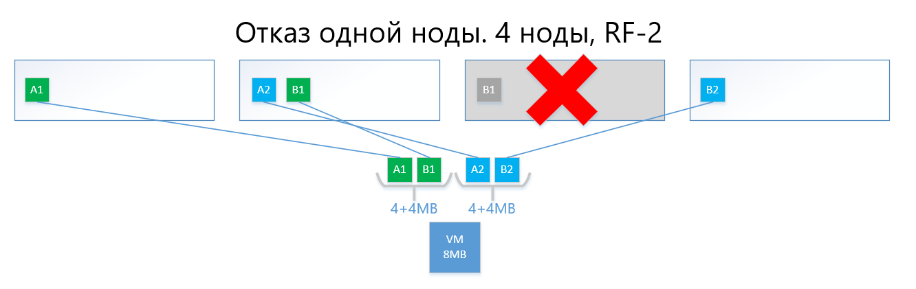
Thus, the virtual disk (and VMs, respectively) will easily survive the failure of one node in the RF-2 scheme.
A circuit with replication, with its simplicity and reliability, suffers from the same sore as RAID1 - there is little usable space.
2) Erasure coding or deletion coding (also known as “redundant coding”, “erasure coding” or “redundancy code”) just exists to solve the problem above. EC is a redundancy scheme that provides high data availability with less disk overhead compared to replication. The principle of operation of this mechanism is similar to RAID 5, 6, 6P.
When encoding, the EC process divides the virtual block (4 MB by default) into several smaller “pieces of data” depending on the EC scheme (for example, the 2 + 1 scheme divides each 4 MB block into 2 pieces of 2 MB). Further, this process generates “parity chunks” for “pieces of data” of no more than one of the previously separated parts. When decoding, the EC generates the missing pieces, reading the "surviving" data across the cluster.
For example, a virtual disk with an EC scheme 2 + 1, implemented on 4 nodes of the cluster, can easily withstand the failure of one node in the cluster in the same way as RF-2. At the same time, overhead costs will be lower, in particular, the capacity coefficient with RF-2 is 2, and with EC 2 + 1 it will be 1.5.
If it is simpler to describe, the bottom line is that the virtual block is divided into 2-8 (why from 2 to 8 see below) "pieces", and for these pieces the "pieces" of parity of the same volume are calculated.
As a result, data and parity are evenly distributed across all nodes of the cluster. At the same time, as with replication, ARDFS automatically distributes data among nodes in such a way as to prevent the storage of the same data (copies of data and their parity) on one node in order to eliminate the chance of losing data due to the fact that the data and their parity will suddenly end up on the same storage node, which will fail.
Below is an example, with the same virtual machine at 8 MB and 4 nodes, but already with the EC 2 + 1 scheme.
Blocks A and B are divided into two pieces of 2 MB each (two because 2 + 1), that is, A1 + A2 and B1 + B2. Unlike the replica, A1 is not a copy of A2, it is a virtual block A, divided into two parts, also with block B. In total, we get two sets of 4 MB, each of which contains two two-megabyte pieces. Further, for each of these sets parity is calculated with a volume of not more than one piece (i.e. 2 MB), we get an additional + 2 parity pieces (AP and BP). Total we have 4x2 data + 2x2 parity.
Next, the pieces are “laid out” by nodes so that the data does not overlap with their parity. Those. A1 and A2 will not lie on the same node with AP.

In the event of a failure of one node (say, also the third one), the fallen block B1 will be automatically restored from the parity BP, which is stored on node No. 2, and will be activated on a node where there is no B-parity, i.e. pieces of BP. In this example, this is node # 1

I am sure the reader has a question:
“All that you described has long been implemented by both competitors and open source solutions, what is the difference between your implementation of EC in ARDFS?”
And then there will be interesting features of the work of ARDFS.
Erasure coding with emphasis on flexibility
Initially, we provided a rather flexible EC X + Y scheme, where X is equal to a number from 2 to 8, and Y is equal to a number from 1 to 8, but always less than or equal to X. Such a scheme is provided for flexibility. Increasing the number of pieces of data (X) into which the virtual unit is divided allows to reduce overhead, that is, increase the usable space.
An increase in the number of parity pieces (Y) increases the reliability of the virtual disk. The larger the Y value, the more nodes in the cluster can fail. Of course, increasing the amount of parity reduces the amount of usable capacity, but this is a payment for reliability.
The dependence of performance on EC circuits is almost straightforward: the more "pieces", the lower the performance, then, of course, you need a balanced look.
This approach allows administrators the most flexible way to configure extended storage. Within the ARDFS pool, you can use any fault tolerance schemes and their combinations, which is also, in our opinion, very useful.
The table below compares several (not all possible) RF and EC circuits.

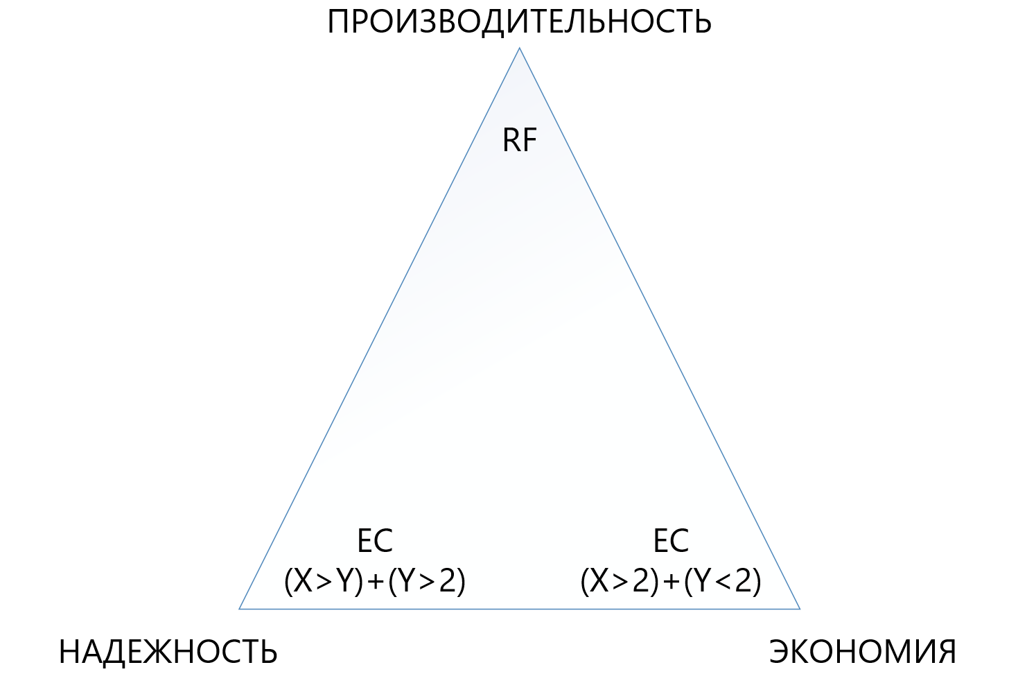
The table shows that even the most “terry” combination of EC 8 + 7, which allows loss of up to 7 nodes in a cluster at the same time, “eats up” less usable space (1,875 against 2) than standard replication, and protects 7 times better, which makes this protection mechanism, although more complex, but much more attractive in situations where you need to ensure maximum reliability in the conditions of lack of disk space. At the same time, you need to understand that each “plus” to X or Y will be an additional overhead for performance, so you need to choose very carefully in the triangle between reliability, economy and performance. For this reason, we will devote a separate article to sizing deletion coding.
Reliability and autonomy of the file system
ARDFS runs locally on all nodes of the cluster and synchronizes them using its own means through dedicated Ethernet interfaces. The important point is that ARDFS independently synchronizes not only data, but also metadata related to storage. While working on ARDFS, we simultaneously studied a number of existing solutions and we found that many do file system meta synchronization using an external distributed DBMS, which we also use to synchronize, but only configurations, not FS metadata (about this and other related subsystems in the next article).
Synchronizing FS metadata using an external DBMS is, of course, a working solution, but then the consistency of the data stored on ARDFS would depend on the external DBMS and its behavior (and she, frankly, is a capricious lady), which is bad in our opinion. Why? If the metadata of the FS is damaged, the FS data itself can also be said “goodbye”, so we decided to take a more complex but reliable path.
We made the metadata synchronization subsystem for ARDFS independently, and it lives absolutely independently of the adjacent subsystems. Those. no other subsystem can corrupt ARDFS data. In our opinion, this is the most reliable and correct way, and is it really so - time will tell. In addition, with this approach, an additional advantage appears. ARDFS can be used independently of vAIR, just like extended storage, which we will certainly use in future products.
As a result, having developed ARDFS, we got a flexible and reliable file system that gives you a choice where you can save on capacity or give everything away on performance, or make storage highly reliable for a moderate fee, but reducing performance requirements.
Together with a simple licensing policy and a flexible delivery model (looking ahead, it is licensed by vAIR by nodes, and is delivered either by software or as a PAC) this allows you to very precisely tailor the solution to the most different requirements of customers and in the future it is easy to maintain this balance.
Who needs this miracle?
On the one hand, we can say that there are already players on the market who have serious decisions in the field of hyperconvergence, and where we are actually going. This statement seems to be true, BUT ...
On the other hand, going “into the fields” and communicating with customers, we and our partners see that this is not at all the case. There are many problems for the hyperconvergent, somewhere people simply did not know that there were such solutions, somewhere it seemed expensive, somewhere there were unsuccessful tests of alternative solutions, but somewhere they generally forbid buying, because of sanctions. In general, the field was not plowed, so we went to raise the virgin lands))).
When is storage better than GCS?
In the course of working with the market, we are often asked when it is better to use the classical scheme with storage, and when - hyper convergent? Many companies - manufacturers of GCS (especially those that do not have storage in their portfolio) say: "Storage is outlived, only hyperconvergent!" This is a bold statement, but it does not quite reflect reality.
In truth, the storage market, indeed, swims towards hyperconvergent and similar solutions, but there is always a “but”.
Firstly, the data centers and IT infrastructures built according to the classical scheme with storage systems cannot be easily rebuilt like this, therefore the modernization and completion of such infrastructures is still a legacy of 5-7 years.
Secondly, those infrastructures that are now being built in large part (meaning the Russian Federation) are being built according to the classical scheme using storage systems and not because people do not know about hyperconvergent, but because the hyperconvergent market is new, solutions and standards have not yet been established , IT employees are not yet trained, there is little experience, and we need to build data centers here and now. And this trend is for another 3-5 years (and then another legacy, see paragraph 1).
Thirdly, a purely technical limitation in additional small delays of 2 milliseconds per write (excluding the local cache, of course), which are fees for distributed storage.
Well, let's not forget about using large physical servers that love the vertical scaling of the disk subsystem.
There are many necessary and popular tasks where the storage system behaves better than the GCS. Here, of course, those manufacturers who do not have storage systems in their product portfolio will disagree with us, but we are ready to argue reasonably. Of course, we, as the developers of both products in one of the future publications, will definitely make a comparison of storage systems and GCS, where we will clearly demonstrate what is better under what conditions.
And where will hyperconverged solutions work better than storage systems?
Based on the theses above, there are three obvious conclusions:
- Where an additional 2 milliseconds of recording delays that occur steadily in any product (now we are not talking about synthetics, you can show nanoseconds on synthetics) are non-critical, hyper convergent will do.
- Where the load from large physical servers can be turned into many small virtual ones and distributed by nodes, the hyper convergent will also go there well.
- Where horizontal scaling is more priority than vertical, GCS will also work fine there.
What are these solutions?
- All standard infrastructure services (directory service, mail, EDS, file servers, small or medium ERP and BI systems, etc.). We call this "general computing."
- The infrastructure of cloud providers, where it is necessary to quickly and standardize horizontally expand and easily "slice" a large number of virtual machines for clients.
- Infrastructure of virtual desktops (VDI), where many small user virtuala are launched and quietly "float" inside a uniform cluster.
- Branch networks, where in each branch you need to get a standard, fault-tolerant, but at the same time inexpensive infrastructure of 15-20 virtual machines.
- Any distributed computing (big data services, for example). Where the load does not go “deep”, but “breadth”.
- Test environments where additional small delays are acceptable, but there are budgetary constraints, because these are tests.
At the moment, we have made AERODISK vAIR just for these tasks and are focusing on them (successfully so far). Perhaps this will change soon. the world does not stand still.
So…
This completes the first part of a large series of articles; in the next article we will talk about the solution architecture and the components used.
We welcome questions, suggestions and constructive disputes.
All Articles