Android for the radio engineer (part two)
In the first part, I talked a little about the RF & Microwave Toolbox application. In the second part I’ll tell you about an equally interesting application that allows you to design microwave devices (mainly planar) on a smartphone / tablet running Android OS. If you are interested, then welcome under the cat…
Development of automation tools for the design of microwave devices began quite a while ago. And I missed this beginning :) Therefore, I will start from the moment when I connected to the development process.
It was 2000 AD, when, as a 3rd year student of the 4th faculty of the Moscow Aviation Institute , I came to work in the linear section of the Center for Special Developments of the Moscow Research Institute of Radio Communications (or simply the Central Research Center of the Moscow Scientific Research Institute of Radio Engineering). The time was hard - there was no sausage, and the computers were slow and worked under DOS . And under DOS worked Super-Compact . And, for example, the task of calculation and optimization in the frequency domain of the microstrip matching circuit looked like this :
BLK
TRL 1 2 Z = 50 P = 34.817MM K = 1
TRL 2 3 Z = 50 P = 299.79MM K = 1
TRL 1 0 Z = 50 P =? 85.444MM? K = 1
RES 2 0 R = 40
BR: 1POR 1
End
Freq
STEP 0.8GHZ 1.2GHZ 100MHZ
End
OUT
PRI BR S
End
OPT
BR
F = 1GHZ MS11
End
DATA
SUB: MS H = 0.5mm ER = 2.2 TAND = 0.01 MET1 = CU 30E-6
End
Well, remember? :) I think that older comrades and my peers remember this software .
Super-Compact was good at running on 386 PCs . The problem was that working with a complex circuit was not very convenient, because when a schematic or topological error occurred, it was difficult to detect, because there was no graphical representation of the circuit or topology (only if the developer had a piece of paper).
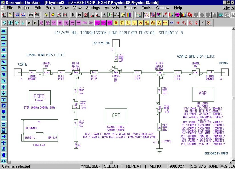
Since 2001, normal working PCs running under Windows XP have appeared . And with them came more advanced design systems - Serenade (from developer S-Compact, Compact Software)
and AWR Microwave Office.

Serenade at that time was very good - the window interface, a huge number of types of graphs, various circuit elements, rich technical documentation ... But most importantly, Serenade could read text files written under S-Compact and play back the topology (!) Of the designed device . It was very cool and thanks to this we were able to find errors in old projects.
AWR Microwave Office also did not lag behind. Its main advantage, in my opinion, was a more convenient and understandable interface, within which it was possible to create complex projects, for the calculation of which different modules were used (circuitry, electrodynamics, data files, NET-lists, etc.).
Now these microwave CAD systems have evolved and turned into powerful and voluminous tools that can solve a variety of problems.
What united all these CAD systems? (In addition to the fact that this software is designed to calculate microwave devices). But they were united by the fact that all these programs used the Oliner method to calculate microwave devices . Those. any microwave device being designed could be represented as compounds of various heterogeneities - segments of transmission lines, bevels, tees, etc. Each heterogeneity is a graphic block, a kind of "brick" from which the entire device is built. This method has proven itself quite well and is still used in many microwave CAD systems (not only those that I wrote about above).
Good, you say. It's like that. But what is it for?
But to what ...
It also allows simulation of microwave devices using the Oliner method. But you can run it on a smartphone or tablet. Personally, I prefer to use this softinka on the tablet - it’s more convenient.
Let's see what RF Designer , created by MMC Technologies LLC, can do .
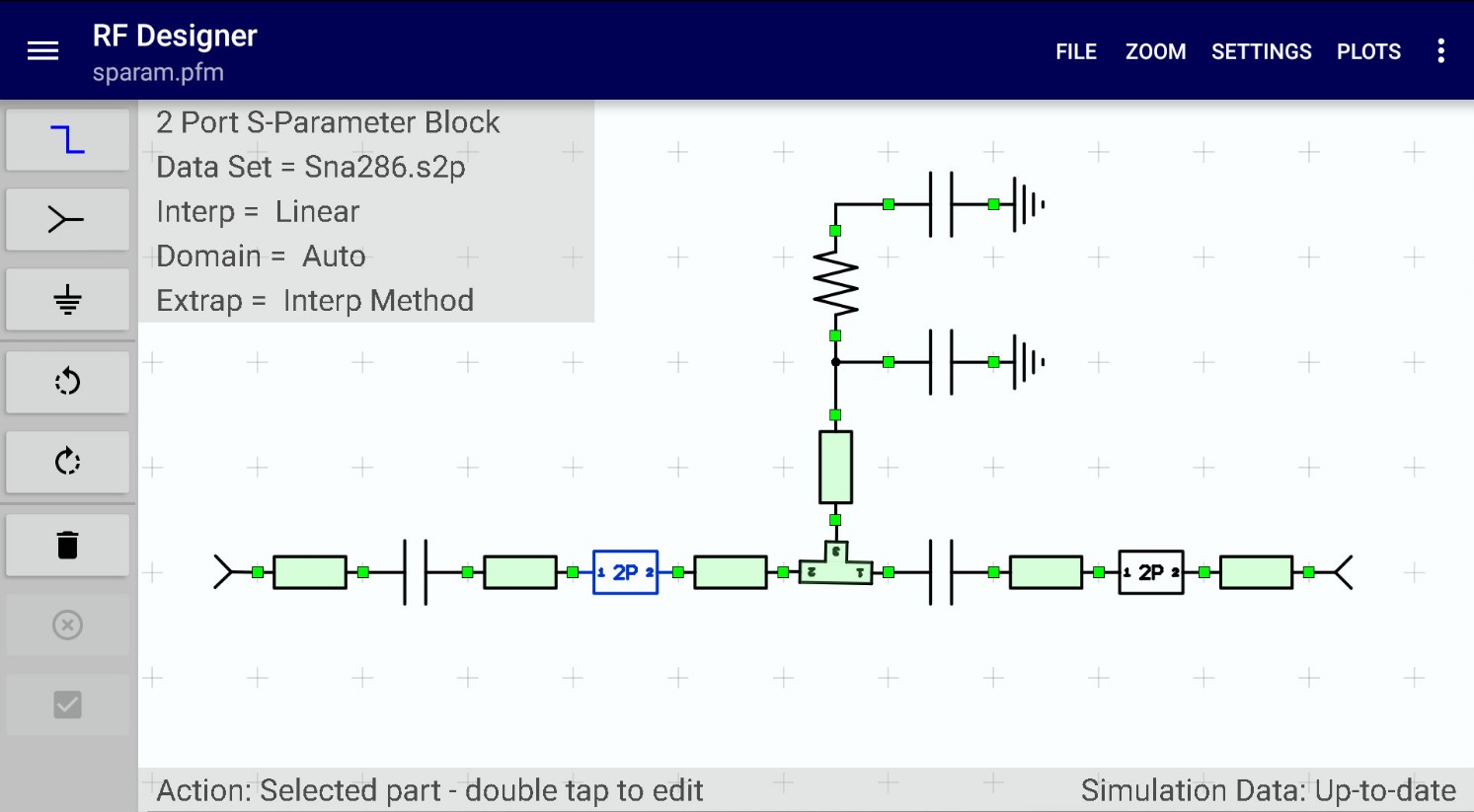
1. First of all, this is creating a circuit in the format that many developers have gotten used to since the times of Serenade and Microwave Office, which I wrote about above (that’s why I needed a historical digression :)).

For example, the loop directional coupler in the figure above consists of only two different elements - a segment of a microstrip line (four-terminal) with a given geometry and a tee (six-terminal) with a given geometry. And you already get the opportunity to evaluate the topology of the device, which will not only produce power division, but also a phase shift of 90 degrees.
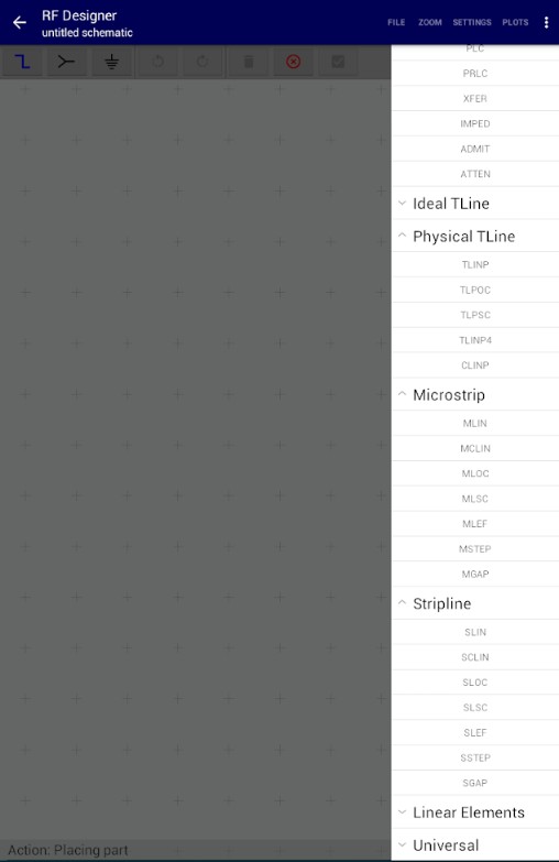
To date, the softink contains the following categories of elements:
• Lumped Elements (lumped elements) - ideal resistor, capacitor, inductance, transformer, attenuator, etc .;
• Ideal Transmission Lines (ideal transmission lines);
• Physical Transmission Lines;
• Microstrip (microstrip lines, MPL) - MPL segment, connected MPL, MPL tee, etc .;
• Stripline (strip lines, submarines) - a segment of submarines connected by submarines, a tee of submarines, etc .;
• Linear Elements (linear elements) - 1-, 2-, 3- and 4-port data blocks;
• Universal Elements (universal elements) - amplifier, isolator , circulator , etc.
For each item, you can get a short help. Here, for example, help for the Physical Transmission Line element.

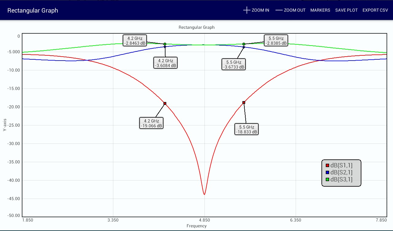
2. After the desired scheme has been created, its analysis is carried out and the obtained data can be presented in the format:
• graphics in Cartesian coordinates
• graphics on the Wolfert-Smith diagram
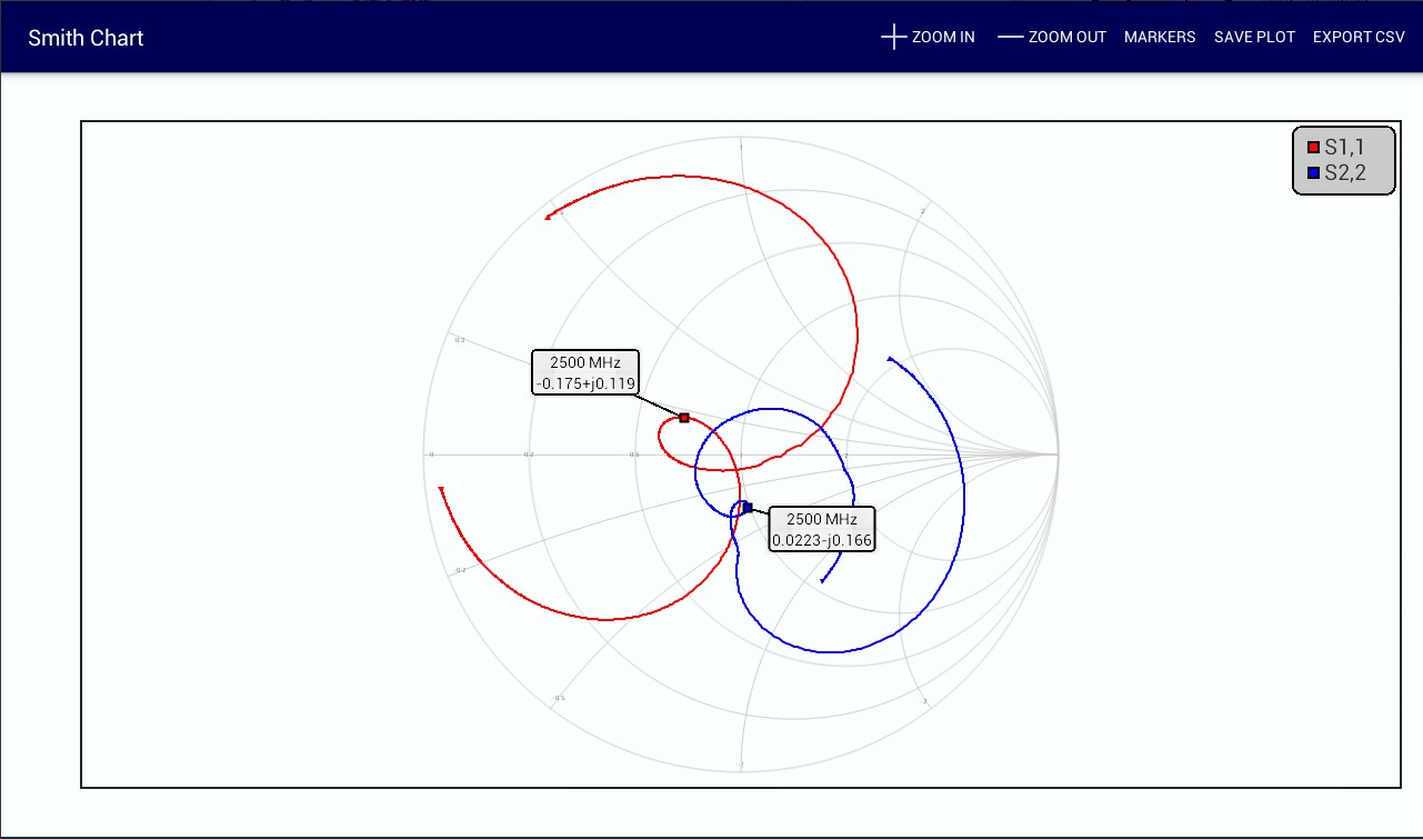
• a table containing numerical data
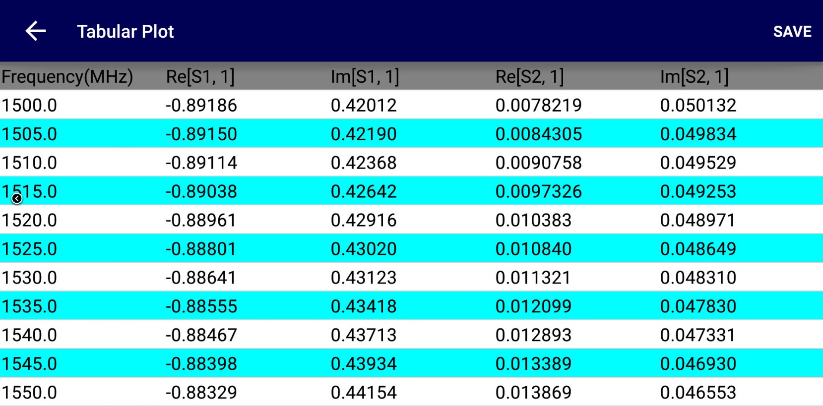
• export data to an S-parameter file
3. During the simulation, you can import and integrate a third-party element / functional unit into the device under development. This element should be presented in the form of an S-parameter file and have no more than 4 ports (this is what Linear Elements is for).
or even so

4. RF DEsigner conducts linear modeling of devices (it’s a pity, of course, that non-linear devices cannot be simulated) containing no more than 4 ports. The maximum number of frequency points that can be set during the simulation is 2001. By default, the wave impedance of the ports is 50 Ohms, but can be adjusted for the user's goals.
As you can see, RF Designer is no longer just an RF calculator. This is a full-fledged CAD CAD operating under the Android OS. And in terms of its level, it is not much inferior to other microwave CAD systems of the early 2000s. This, I must say, is a fairly high level (see the links in the Sources section at the end of the article).
And in conclusion of everything I’ve written, I want to say that MMC Technologies has its own Youtube channel where you can watch videos explaining the modeling process in RF Designer.
In my opinion, the most interesting and informative are:
• RF Designer - Getting Started
• RF Designer - Microstrip Branchline Coupler
The video shows that when you connect a mouse and keyboard to the device, the convenience of working with software increases significantly.
Well, in the end, as usual, a spoonful: the application exists only in one form - paid. Unfortunately, there is no trial version. But unlike modern commercial microwave CAD systems, the price of which is measured in hundreds of thousands of dollars, RF DEsigner costs only $ 6.
Frankly, when I discovered this application, I did not hesitate to buy it. And then he played for a long time, simulating various filters taken from the book Microstrip filters for RF and Microwave applications, Hong, 2011. And by the way, the coincidence with the examples given in the book was quite good :)
Dear habravchane, thank you for your attention!
I will be glad to your comments, links to interesting softinki and your favorite modeling tools.
1. For those who worked with Super-Compact, this note from Microwaves will be interesting. I almost cried right :)
2. Unfortunately, I could not find the original screen images running S-Compact. So I took an example from here . If you found screenshots with S-COMPACT, please write in the comments.
3. If interested, here is a 1997 article in the journal Applied Microwave & Wireless on CAD / CAM Serenade 7.0 . And this is the article where I took screenshots from.
4. This refers precisely to the method underlying the calculation of planar microwave structures. A more detailed description can be obtained from the book “Electrodynamics and microwave technology for CAD users”, Banks S.E., Kurushin A.A., clause 8.3. "The Oliner Method."
5. If you are interested, the basic idea of building a microwave CAD system was presented in the book “Machine Design of Microwave Devices”, Gupta, Garge, Chadha, Radio and Communication Publishing House, Moscow, 1987. By the way, a cool book. At one time, based on her motives, he wrote a number of term papers and calculations.
But first, a short historical excursion.
Development of automation tools for the design of microwave devices began quite a while ago. And I missed this beginning :) Therefore, I will start from the moment when I connected to the development process.
It was 2000 AD, when, as a 3rd year student of the 4th faculty of the Moscow Aviation Institute , I came to work in the linear section of the Center for Special Developments of the Moscow Research Institute of Radio Communications (or simply the Central Research Center of the Moscow Scientific Research Institute of Radio Engineering). The time was hard - there was no sausage, and the computers were slow and worked under DOS . And under DOS worked Super-Compact . And, for example, the task of calculation and optimization in the frequency domain of the microstrip matching circuit looked like this :
BLK
TRL 1 2 Z = 50 P = 34.817MM K = 1
TRL 2 3 Z = 50 P = 299.79MM K = 1
TRL 1 0 Z = 50 P =? 85.444MM? K = 1
RES 2 0 R = 40
BR: 1POR 1
End
Freq
STEP 0.8GHZ 1.2GHZ 100MHZ
End
OUT
PRI BR S
End
OPT
BR
F = 1GHZ MS11
End
DATA
SUB: MS H = 0.5mm ER = 2.2 TAND = 0.01 MET1 = CU 30E-6
End
Well, remember? :) I think that older comrades and my peers remember this software .
Super-Compact was good at running on 386 PCs . The problem was that working with a complex circuit was not very convenient, because when a schematic or topological error occurred, it was difficult to detect, because there was no graphical representation of the circuit or topology (only if the developer had a piece of paper).
Since 2001, normal working PCs running under Windows XP have appeared . And with them came more advanced design systems - Serenade (from developer S-Compact, Compact Software)
and AWR Microwave Office.
Serenade at that time was very good - the window interface, a huge number of types of graphs, various circuit elements, rich technical documentation ... But most importantly, Serenade could read text files written under S-Compact and play back the topology (!) Of the designed device . It was very cool and thanks to this we were able to find errors in old projects.
AWR Microwave Office also did not lag behind. Its main advantage, in my opinion, was a more convenient and understandable interface, within which it was possible to create complex projects, for the calculation of which different modules were used (circuitry, electrodynamics, data files, NET-lists, etc.).
Now these microwave CAD systems have evolved and turned into powerful and voluminous tools that can solve a variety of problems.
What united all these CAD systems? (In addition to the fact that this software is designed to calculate microwave devices). But they were united by the fact that all these programs used the Oliner method to calculate microwave devices . Those. any microwave device being designed could be represented as compounds of various heterogeneities - segments of transmission lines, bevels, tees, etc. Each heterogeneity is a graphic block, a kind of "brick" from which the entire device is built. This method has proven itself quite well and is still used in many microwave CAD systems (not only those that I wrote about above).
Good, you say. It's like that. But what is it for?
But to what ...
RF Designer for Android
It also allows simulation of microwave devices using the Oliner method. But you can run it on a smartphone or tablet. Personally, I prefer to use this softinka on the tablet - it’s more convenient.
Let's see what RF Designer , created by MMC Technologies LLC, can do .
1. First of all, this is creating a circuit in the format that many developers have gotten used to since the times of Serenade and Microwave Office, which I wrote about above (that’s why I needed a historical digression :)).
For example, the loop directional coupler in the figure above consists of only two different elements - a segment of a microstrip line (four-terminal) with a given geometry and a tee (six-terminal) with a given geometry. And you already get the opportunity to evaluate the topology of the device, which will not only produce power division, but also a phase shift of 90 degrees.
To date, the softink contains the following categories of elements:
• Lumped Elements (lumped elements) - ideal resistor, capacitor, inductance, transformer, attenuator, etc .;
• Ideal Transmission Lines (ideal transmission lines);
• Physical Transmission Lines;
• Microstrip (microstrip lines, MPL) - MPL segment, connected MPL, MPL tee, etc .;
• Stripline (strip lines, submarines) - a segment of submarines connected by submarines, a tee of submarines, etc .;
• Linear Elements (linear elements) - 1-, 2-, 3- and 4-port data blocks;
• Universal Elements (universal elements) - amplifier, isolator , circulator , etc.
For each item, you can get a short help. Here, for example, help for the Physical Transmission Line element.
2. After the desired scheme has been created, its analysis is carried out and the obtained data can be presented in the format:
• graphics in Cartesian coordinates
• graphics on the Wolfert-Smith diagram
• a table containing numerical data
• export data to an S-parameter file
3. During the simulation, you can import and integrate a third-party element / functional unit into the device under development. This element should be presented in the form of an S-parameter file and have no more than 4 ports (this is what Linear Elements is for).
or even so
4. RF DEsigner conducts linear modeling of devices (it’s a pity, of course, that non-linear devices cannot be simulated) containing no more than 4 ports. The maximum number of frequency points that can be set during the simulation is 2001. By default, the wave impedance of the ports is 50 Ohms, but can be adjusted for the user's goals.
As you can see, RF Designer is no longer just an RF calculator. This is a full-fledged CAD CAD operating under the Android OS. And in terms of its level, it is not much inferior to other microwave CAD systems of the early 2000s. This, I must say, is a fairly high level (see the links in the Sources section at the end of the article).
And in conclusion of everything I’ve written, I want to say that MMC Technologies has its own Youtube channel where you can watch videos explaining the modeling process in RF Designer.
In my opinion, the most interesting and informative are:
• RF Designer - Getting Started
• RF Designer - Microstrip Branchline Coupler
The video shows that when you connect a mouse and keyboard to the device, the convenience of working with software increases significantly.
Conclusion
Well, in the end, as usual, a spoonful: the application exists only in one form - paid. Unfortunately, there is no trial version. But unlike modern commercial microwave CAD systems, the price of which is measured in hundreds of thousands of dollars, RF DEsigner costs only $ 6.
Frankly, when I discovered this application, I did not hesitate to buy it. And then he played for a long time, simulating various filters taken from the book Microstrip filters for RF and Microwave applications, Hong, 2011. And by the way, the coincidence with the examples given in the book was quite good :)
Dear habravchane, thank you for your attention!
I will be glad to your comments, links to interesting softinki and your favorite modeling tools.
Sources
:1. For those who worked with Super-Compact, this note from Microwaves will be interesting. I almost cried right :)
2. Unfortunately, I could not find the original screen images running S-Compact. So I took an example from here . If you found screenshots with S-COMPACT, please write in the comments.
3. If interested, here is a 1997 article in the journal Applied Microwave & Wireless on CAD / CAM Serenade 7.0 . And this is the article where I took screenshots from.
4. This refers precisely to the method underlying the calculation of planar microwave structures. A more detailed description can be obtained from the book “Electrodynamics and microwave technology for CAD users”, Banks S.E., Kurushin A.A., clause 8.3. "The Oliner Method."
5. If you are interested, the basic idea of building a microwave CAD system was presented in the book “Machine Design of Microwave Devices”, Gupta, Garge, Chadha, Radio and Communication Publishing House, Moscow, 1987. By the way, a cool book. At one time, based on her motives, he wrote a number of term papers and calculations.
All Articles