Architecture and programming Fairchild Channel F
“Channel F homebrew would be like programming sprites via hardware jumpers ...”
/ chadtower, atariage forum /
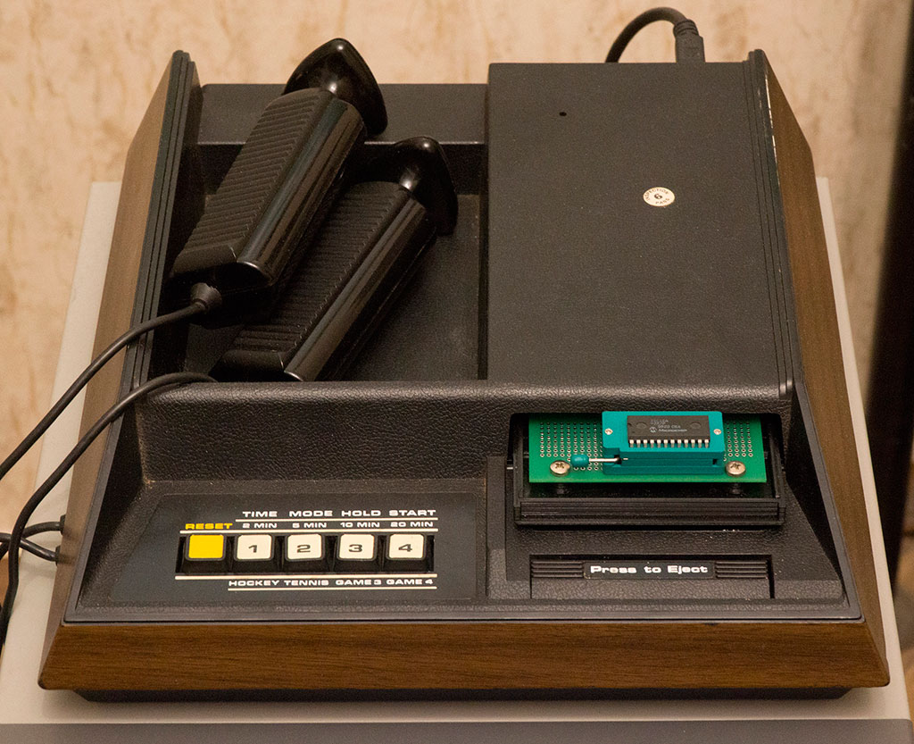
The Fairchild Channel F game console, also known as VES, appeared in November 1976. Unlike its predecessors such as Ping-Pong, Tennis (in the same row - the Soviet “Video Sport”), it had a very significant difference - the presence of a microprocessor and cartridges with programs. Prior to this, games in consoles were implemented on strict logic - the program, in the modern sense, was absent there.
Fairchild Channel F was released until 1983. During this time, more than a quarter of a million of these consoles were sold and about 30-40 games were released , some of which were already in the 2000s.
Speaking about the superiority in terms of using a microprocessor, it is worth noting that RCA Studio II, which I talked about in a previous article, was only a couple of months late, but turned out to be significantly weaker than Channel F, which is why it failed in sales. However, the appearance, less than a year later, Atari VCS - and replaced Channel F. from the market.
The development of Fairchild_Channel_F, as such, was not. In System II and several clones, such as Saba Videoplay 2 (1979), the differences were mainly in the case, joysticks (by the way, they all understood, apart from the usual positions, the rotation of the knob) and the number of chips. Architecturally, everything was almost identical.
What is Channel F?
The processor, in the traditions of the era, was produced by the same Fairchild company as the console itself and is called F8 en.wikipedia.org/wiki/Fairchild_F8 . This is an 8-bit processor from 1974, operating at a frequency of 1.8 MHz (one instruction takes from 1 to 6 clock cycles).
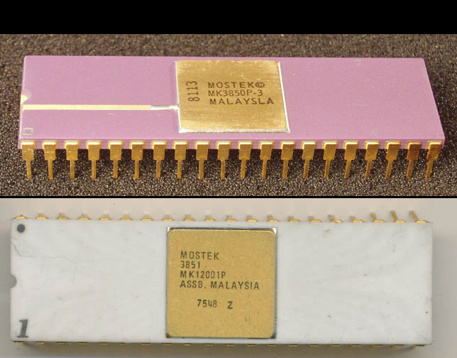
However, it can be called a microprocessor only with a stretch, since this processor consists of two chips - a 3850CPU computing device containing ALU, a battery, 64 bytes of SRAM, the logic necessary to execute the instructions, two ports (there is no address bus!) And 3851PSU (Programmable Storage Unit), which contains 1kb of ROM (used for BIOS), an instruction pointer, memory addressing schemes, interrupts, a timer (interrupts and a timer are not used specifically in Channel F).
Later, the F3859 chip appeared, which combined the CPU and PSU on the same chip and Mostek 3870, a slightly improved version that was produced until the 1990s. However, this is another story. Interestingly, sometimes the F8 is called a microcontroller (in particular, due to the presence of a timer and ports) and is referred to as the ancestor of the Intel MCS-48 family (8048).
In addition to Channel F, the F8 processor was also used in the VideoBrain computer and in the CompuChess chess computer. In general, it is surprising that there is very little information about this processor. With the exception of a couple of descriptions from Fairchild and the source code for several games and examples specifically for Channel F, there’s nothing more. It seems that this processor has not been used anywhere else, which seems incredible (given that its advanced versions have been released for quite some time). I will assume that all other devices where it was used were for military purposes.
Now a little about the features of the processor. Reflect on the set and functions of its registers. I think this is one of the most confused architectures that existed at that time (probably modern ones can stretch, but the comparison will be incorrect, because they are designed for compilers. Living people worked with F8).
There are a lot of registers in the processor. In addition to the 8-bit battery A and the flag register W (I, O, Z, C, S), there is also a “scratchpad” - 64 eight-bit cells with various functions.
The first nine cells are used as general purpose registers R0-R8 in commands like 'lr a, 7 "(load the contents of register R7 into the battery). Note that the letter R is not indicated - only the register number is written. What exactly is meant, the number or the number should be clear from the context. Say, in the case of the lr instruction, there simply cannot be numbers. And if, for example, “li 7" (load a constant into the battery), then it is exactly a number, not a register.
Cells 9, 10-11 (H), 12-13 (K), 14-15 (Q) are designed to save other registers in different situations, such as calling subprograms.
Registers R16-R63 are accessible only through a special ISAR index register (Indirect Scratchpad Address Register), as six eight-byte buffers that are formed from cells 16-23, 24-31, 32-39, 40-47, 48-55, 56-63 .
The six-bit ISAR is divided into two parts of 3 bits. When ISAR is increased or decreased by one, only the lower 3 digits are affected - i.e. addressing is carried out within one of the six eight-byte buffers mentioned (at the same time, the end of the buffer can be traced by the special br7 conditional branch instructions).
In this case, “d” in the instruction “lr d, a” is not the name of the register, but a sign that the ISAR will need to be reduced (“i” - increase, “s” - leave unchanged).
There is another way of indirect addressing - through the DC0 register (Data Counter):
If you need to transfer data from one memory area to another, then the xdc command is additionally used, which swaps the contents of the registers DC0 and DC1. Those. read from the address pointed to by DC0, then do xdc and write to the address that DC1 now points to. Then again xdc, etc. Those. DC1 is a kind of shadow register for storing a copy of DC0. Directly accessing it (except for the command xdc) is impossible.
The above examples illustrate only part of the possibilities in terms of addressing, in fact, there are more of them.
Also in F8 there are four ports - 0,1,4,5, which can be written with the out command and read with the in command. In Channel F, ports are used to output graphics, sound, and read the status of the joystick.
I will not dwell on other instructions such as arithmetic, transitions, and so on - they are fairly standard. I only note that the choice of registers over which you can perform actions is very limited, so the code grows rapidly due to the need to constantly move values back and forth.
There is no subtraction (there is only addition). The decrement (ds) and increment (inc) instructions per unit are asymmetric. ds only works with the registers r0-r8, inc - only with the battery.
Unconditional jump spoils the battery.
Example of a normal loop:
Since F8 does not have a hardware stack, there are difficulties with nested subprogram calls. A normal call and return looks like this:
Here PC0 is a regular instruction pointer. PC1 - the so-called "stack register". It has nothing to do with the stack, just PC0 is saved in it when the subroutine is called.
If another subroutine is called from sub, the return address is overwritten and needs to be complicated (save the first return address in register K):
If you also need a third level of nesting, then everything becomes completely sad (in the BIOS for this there are even two special routines - pushk and popk).
The general recommendation is to try to replace subroutine calls with macros. Of course, if there are no strict restrictions on the size of the code.
There is no hardware stack in F8. If necessary, it is implemented programmatically - through ISAR and buffers.
Writing to RAM is not very relevant (for lack of one), but it looks like this:
Although this sounds a little strange, there is no RAM in Fairchild Channel F. The existing two kilobytes of video memory (MK4027) are not displayed in the address space, and indeed they are not readable, they are written to through ports. The registers of the microprocessor, even though there are as many as 64, are hardly considered correct for RAM.
The executable program is stored in removable ROM cartridges, most often having a capacity of 2kb (some modern games use 3k, 4k and 5k cartridges). In addition, there is a built-in processor chip, 1KB BIOS ROM, containing a simple game such as Tennis, a couple of useful routines and images of several characters.
In the address space, the BIOS is located from $ 0000 to $ 07ff, the cartridge ROM - from $ 0800.
Channel F's graphical capabilities are very primitive, since there is simply no video controller in the form of a separate chip there - everything is implemented on the usual logic such as shift registers, gates, and operational amplifiers. It is rather unusual that different sources mention different resolutions, and there are a lot of options. The fact is that the available 2 kilobytes of video memory imply a resolution of 128 x 64, but in reality this is far from the case. Firstly, a lot depends on what area of the formed image on this particular TV is visible (because of which the first 4 columns are not officially used at all). Secondly, the last few columns are used under the palette. Thirdly, part of the memory is not used at all.
As a result, the actual resolution can be roughly estimated as 95 x 58 pixels with 8 colors (which, however, is much better than RCA Studio II with its black and white 64x32).
Most consoles are released in the NTSC version, but PAL also exist. There are no practical differences, as they say (the number of lines is the same).
Essentially, such a simple iron only allows you to draw dots on the screen. Although the total number of displayed colors is 8, however, only four can be displayed within one line (you can arbitrarily call this a palette). The palette is set individually for each line, and is stored in a rather strange place - in columns 125 and 126 of each of the lines (which in any case are outside the visible area). Changing the palette is, respectively, by drawing pixels in these two columns.

(the area of video memory that is actually visible on the screen and the area where the palette is set are highlighted in yellow)
As noted above, there is only one way to write data to VRAM - through the ports. This indicates the color, column, row:
X is written to port 4, Y to port 5, the color to port 1, after which the data are transferred by writing a constant to port 0:
A delay is required so that everything can be recorded, otherwise the next point may not be drawn. In the official version, 4 is still added to the column and row (omitted for simplicity)
Filling the entire screen with dots (in a loop) thus takes about a second. It is important to note that in addition to the extremely slow screen update, there is also the fact that there is no way to wait for the beam to reverse in the frame. Accordingly, even a small redraw is inevitably accompanied by a flicker.
Now about the palette. Strictly speaking, for each line there are two modes - black and white (when the background is black and the foreground is only white, no matter what pixel is drawn) and color.
In the foreground color mode, there are always three - red, green, blue (rgb). Plus one of the three background colors - gray, light blue, light green.
To set the palette in columns 125 and 126, write the following values:
In typical games, they usually do this: first they set a certain general background, for which you can use the ready-made BIOS procedure:
Then, if necessary, make a strip with a black and white palette (for example, to display the game score with white numbers on a black background)
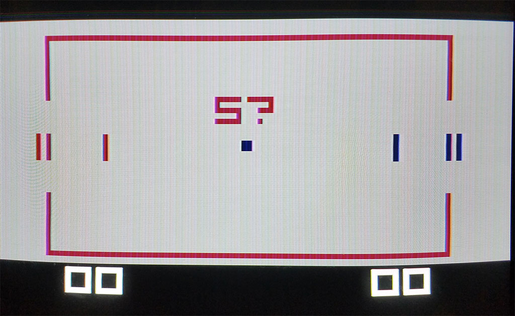
And then they put pixels in one of three colors (if the background is gray, respectively - r, g, b). As a result, there are of course 8 colors, but to put in a specific place a point of an arbitrary color is so easy - it is impossible. Here is a set of pictures that give some idea of the colors and their combinations.
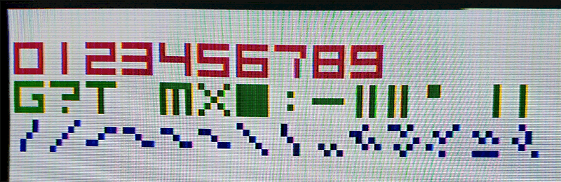
Actually, on this all the graphics, as such, end - everything that you want to do is done by drawing pixels, and manually. From useful routines, the BIOS has character output. However, for reasons of space saving, in the ROM there are only images of numbers and individual characters, 5x8 pixels in size:
However, the procedure for their withdrawal is useful and can be used as follows:
In the above version, the upper two digits in the register r0 determine the color (10 - red, 11 - green, 01 - blue, 00 - transparent), the rest - the serial number of the character (0 1 2 3 4 5 6 7 8 9 G? T SPACE MX BLOCK: - center || left || `), starting from zero. Registers r1 and r2 are placed, respectively, a column and a row.
A more practical option is not to think about bits:
To get a feel for the platform, I wrote a 256-byte intro for the tiny intro contest at Chaos Constructions'2019 . Nothing special, but pay attention to why the line-by-line palette change is used there. A creeping horizontal strip, as it were, highlights the line that is under it, temporarily replacing the entire background with black, and all pixels with white. Since you do not need to overwrite the pixels themselves (and do not need to restore them later), you can make such a “backlight” very fast and without flicker.
The second point is the letters "CC". Since the letters “C” are not in the BIOS, the overlapping of the letters GG and the number 1 are used to obtain the inverse “CC”.
Sound is bad. Officially, there are three sounds - 120Hz, 500 Hz and 1 KHz. In fact, getting something other than clicks and a choked squeak is problematic. In addition, they say that between PAL and NTSC machines, as well as between old and new versions, the sound is also different. However, for typical games - it’s enough. Sound on and off through the ports:
People even had fun playing music. The best samples remotely resemble PC-Speaker. True, there is no practical sense anyway - all processor resources go to music, nothing special can be done.
Currently, there is a ready-made selection of the necessary software called “Development Pack”.
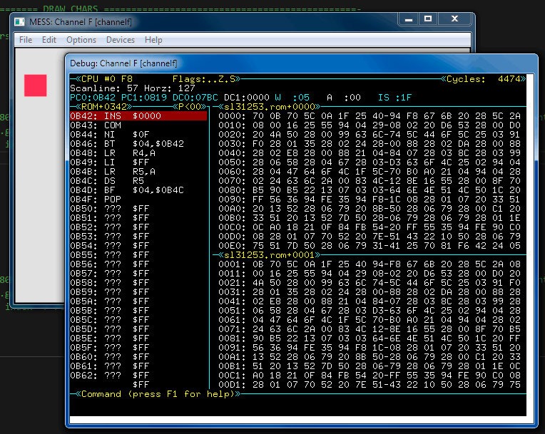
This includes DASM assembler, disassembler, MESS emulator (with debugger). All this works without problems at least under Windows 7.
Parameters for assembly and startup:
The emulator is quite good, although the debugger there is extremely strange. I could not configure the new version of MAME / MESS right away (I noticed that setting up MAME for an unpopular platform that it supposedly supports is a non-trivial task every time).
The emulator assumes that the resolution of the visible region corresponds to minx = 5, minY = 5, maxX = 105, maxY = 61
Since there is no pleasure in writing something under the emulator without having tested the result live, I had to solve the problem with the ROM emulator. At my request, tnt23 made a special cartridge (Alexander Novozhilov printed a case for it) into which the EEPROM 28C16A is inserted. Due to the peculiarities of F8 addressing, I still had to buy an ancient Fairchild 3853 chip on eBay. As a result, it was possible to program EEPROM to see how the code looks on a live machine.
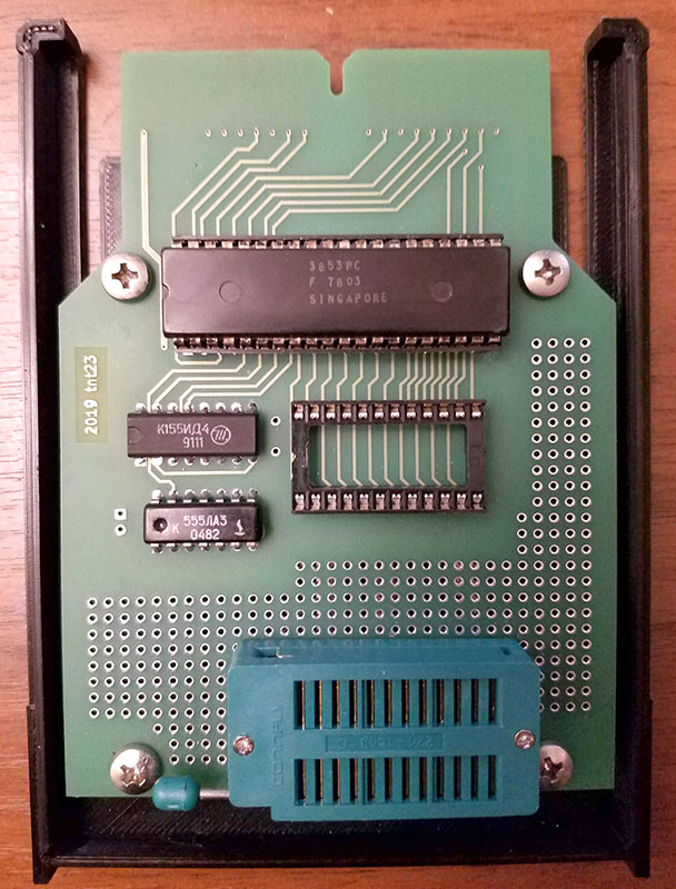
In addition, tnt23 attached a Channel F S-Video output (normally it could only be connected to a TV via the antenna input), which greatly improved image quality and color reproduction.
Story about Fairchild Channel F:
/ chadtower, atariage forum /
The Fairchild Channel F game console, also known as VES, appeared in November 1976. Unlike its predecessors such as Ping-Pong, Tennis (in the same row - the Soviet “Video Sport”), it had a very significant difference - the presence of a microprocessor and cartridges with programs. Prior to this, games in consoles were implemented on strict logic - the program, in the modern sense, was absent there.
Fairchild Channel F was released until 1983. During this time, more than a quarter of a million of these consoles were sold and about 30-40 games were released , some of which were already in the 2000s.
Speaking about the superiority in terms of using a microprocessor, it is worth noting that RCA Studio II, which I talked about in a previous article, was only a couple of months late, but turned out to be significantly weaker than Channel F, which is why it failed in sales. However, the appearance, less than a year later, Atari VCS - and replaced Channel F. from the market.
The development of Fairchild_Channel_F, as such, was not. In System II and several clones, such as Saba Videoplay 2 (1979), the differences were mainly in the case, joysticks (by the way, they all understood, apart from the usual positions, the rotation of the knob) and the number of chips. Architecturally, everything was almost identical.
What is Channel F?
CPU
The processor, in the traditions of the era, was produced by the same Fairchild company as the console itself and is called F8 en.wikipedia.org/wiki/Fairchild_F8 . This is an 8-bit processor from 1974, operating at a frequency of 1.8 MHz (one instruction takes from 1 to 6 clock cycles).
However, it can be called a microprocessor only with a stretch, since this processor consists of two chips - a 3850CPU computing device containing ALU, a battery, 64 bytes of SRAM, the logic necessary to execute the instructions, two ports (there is no address bus!) And 3851PSU (Programmable Storage Unit), which contains 1kb of ROM (used for BIOS), an instruction pointer, memory addressing schemes, interrupts, a timer (interrupts and a timer are not used specifically in Channel F).
Later, the F3859 chip appeared, which combined the CPU and PSU on the same chip and Mostek 3870, a slightly improved version that was produced until the 1990s. However, this is another story. Interestingly, sometimes the F8 is called a microcontroller (in particular, due to the presence of a timer and ports) and is referred to as the ancestor of the Intel MCS-48 family (8048).
In addition to Channel F, the F8 processor was also used in the VideoBrain computer and in the CompuChess chess computer. In general, it is surprising that there is very little information about this processor. With the exception of a couple of descriptions from Fairchild and the source code for several games and examples specifically for Channel F, there’s nothing more. It seems that this processor has not been used anywhere else, which seems incredible (given that its advanced versions have been released for quite some time). I will assume that all other devices where it was used were for military purposes.
Now a little about the features of the processor. Reflect on the set and functions of its registers. I think this is one of the most confused architectures that existed at that time (probably modern ones can stretch, but the comparison will be incorrect, because they are designed for compilers. Living people worked with F8).
There are a lot of registers in the processor. In addition to the 8-bit battery A and the flag register W (I, O, Z, C, S), there is also a “scratchpad” - 64 eight-bit cells with various functions.
The first nine cells are used as general purpose registers R0-R8 in commands like 'lr a, 7 "(load the contents of register R7 into the battery). Note that the letter R is not indicated - only the register number is written. What exactly is meant, the number or the number should be clear from the context. Say, in the case of the lr instruction, there simply cannot be numbers. And if, for example, “li 7" (load a constant into the battery), then it is exactly a number, not a register.
Cells 9, 10-11 (H), 12-13 (K), 14-15 (Q) are designed to save other registers in different situations, such as calling subprograms.
Registers R16-R63 are accessible only through a special ISAR index register (Indirect Scratchpad Address Register), as six eight-byte buffers that are formed from cells 16-23, 24-31, 32-39, 40-47, 48-55, 56-63 .
The six-bit ISAR is divided into two parts of 3 bits. When ISAR is increased or decreased by one, only the lower 3 digits are affected - i.e. addressing is carried out within one of the six eight-byte buffers mentioned (at the same time, the end of the buffer can be traced by the special br7 conditional branch instructions).
clr ; 0 -> A ; set ISAR to full address Ox27 (octal 27) lisu 2 ; buffer N2 lisl 7 ; index within buffer N2 loop: lr d,a ; A-> buffer N2[index], than decrement ISAR (27, 26, 25, ... ) br7 loop ; go further if low part of ISAR contains 7 (end of buffer N2). if not, go loop again
In this case, “d” in the instruction “lr d, a” is not the name of the register, but a sign that the ISAR will need to be reduced (“i” - increase, “s” - leave unchanged).
There is another way of indirect addressing - through the DC0 register (Data Counter):
dci data_addr ; data_addr -> DC0 lm ; [data_addr] -> A, DC0 + 1 -> DC0 ... data_addr: db 0,1,2,3,...
If you need to transfer data from one memory area to another, then the xdc command is additionally used, which swaps the contents of the registers DC0 and DC1. Those. read from the address pointed to by DC0, then do xdc and write to the address that DC1 now points to. Then again xdc, etc. Those. DC1 is a kind of shadow register for storing a copy of DC0. Directly accessing it (except for the command xdc) is impossible.
The above examples illustrate only part of the possibilities in terms of addressing, in fact, there are more of them.
Also in F8 there are four ports - 0,1,4,5, which can be written with the out command and read with the in command. In Channel F, ports are used to output graphics, sound, and read the status of the joystick.
I will not dwell on other instructions such as arithmetic, transitions, and so on - they are fairly standard. I only note that the choice of registers over which you can perform actions is very limited, so the code grows rapidly due to the need to constantly move values back and forth.
There is no subtraction (there is only addition). The decrement (ds) and increment (inc) instructions per unit are asymmetric. ds only works with the registers r0-r8, inc - only with the battery.
Unconditional jump spoils the battery.
Example of a normal loop:
li 25 ; (r4) number of iterations lr 4,a next: ds 4 ; r4-- bnz next ; until r4 == 0
Routines
Since F8 does not have a hardware stack, there are difficulties with nested subprogram calls. A normal call and return looks like this:
; ...code pi sub ; Pushes address of next instruction to PC1 ; address of sub is stored in PC0 (jump to subroutine) ; ...code continues sub: ; ... often used code pop ; Move return address from PC1 to PC0
Here PC0 is a regular instruction pointer. PC1 - the so-called "stack register". It has nothing to do with the stack, just PC0 is saved in it when the subroutine is called.
If another subroutine is called from sub, the return address is overwritten and needs to be complicated (save the first return address in register K):
prog: ; ...do something... pi sub1 ; Address of next instruction stored in PC1 ; sub1 is stored in PC0 (jump to subroutine) ; ...do more... sub1: lr k,p ; Copy PC1 to K, original jump address to K ; ...do something... pi sub2 ; Pushes address of next instruction to PC1 ; sub1 is stored in PC0 (jump to subroutine) ; ...do more... pk ; Store address of next instruction in PC1 ; Copy value in K to PC0 (jump back to main) sub2: ; ...do something... pop ; Move return address from PC1 to PC0
If you also need a third level of nesting, then everything becomes completely sad (in the BIOS for this there are even two special routines - pushk and popk).
The general recommendation is to try to replace subroutine calls with macros. Of course, if there are no strict restrictions on the size of the code.
There is no hardware stack in F8. If necessary, it is implemented programmatically - through ISAR and buffers.
Writing to RAM is not very relevant (for lack of one), but it looks like this:
li $FF ; set value dci $3800 ; set target address st ; write
Memory
Although this sounds a little strange, there is no RAM in Fairchild Channel F. The existing two kilobytes of video memory (MK4027) are not displayed in the address space, and indeed they are not readable, they are written to through ports. The registers of the microprocessor, even though there are as many as 64, are hardly considered correct for RAM.
The executable program is stored in removable ROM cartridges, most often having a capacity of 2kb (some modern games use 3k, 4k and 5k cartridges). In addition, there is a built-in processor chip, 1KB BIOS ROM, containing a simple game such as Tennis, a couple of useful routines and images of several characters.
In the address space, the BIOS is located from $ 0000 to $ 07ff, the cartridge ROM - from $ 0800.
Graphic arts
Channel F's graphical capabilities are very primitive, since there is simply no video controller in the form of a separate chip there - everything is implemented on the usual logic such as shift registers, gates, and operational amplifiers. It is rather unusual that different sources mention different resolutions, and there are a lot of options. The fact is that the available 2 kilobytes of video memory imply a resolution of 128 x 64, but in reality this is far from the case. Firstly, a lot depends on what area of the formed image on this particular TV is visible (because of which the first 4 columns are not officially used at all). Secondly, the last few columns are used under the palette. Thirdly, part of the memory is not used at all.
As a result, the actual resolution can be roughly estimated as 95 x 58 pixels with 8 colors (which, however, is much better than RCA Studio II with its black and white 64x32).
Most consoles are released in the NTSC version, but PAL also exist. There are no practical differences, as they say (the number of lines is the same).
Essentially, such a simple iron only allows you to draw dots on the screen. Although the total number of displayed colors is 8, however, only four can be displayed within one line (you can arbitrarily call this a palette). The palette is set individually for each line, and is stored in a rather strange place - in columns 125 and 126 of each of the lines (which in any case are outside the visible area). Changing the palette is, respectively, by drawing pixels in these two columns.
(the area of video memory that is actually visible on the screen and the area where the palette is set are highlighted in yellow)
As noted above, there is only one way to write data to VRAM - through the ports. This indicates the color, column, row:
X is written to port 4, Y to port 5, the color to port 1, after which the data are transferred by writing a constant to port 0:
; set color (2 bit per pixel) li $00 ; color ($00 = green, $40 = red, $80 = blue, $C0 = background) outs 1 li 104 ; X com outs 4 ; set the row li 61 ; Y com outs 5 ; transfer data to VRAM li $60 outs 0 li $50 outs 0 ; wait for update lis 6 delay: ai $ff bnz delay
A delay is required so that everything can be recorded, otherwise the next point may not be drawn. In the official version, 4 is still added to the column and row (omitted for simplicity)
Filling the entire screen with dots (in a loop) thus takes about a second. It is important to note that in addition to the extremely slow screen update, there is also the fact that there is no way to wait for the beam to reverse in the frame. Accordingly, even a small redraw is inevitably accompanied by a flicker.
Now about the palette. Strictly speaking, for each line there are two modes - black and white (when the background is black and the foreground is only white, no matter what pixel is drawn) and color.
In the foreground color mode, there are always three - red, green, blue (rgb). Plus one of the three background colors - gray, light blue, light green.
To set the palette in columns 125 and 126, write the following values:
x=125 x=126 palette --------------------------------------------------------------------- 00 00 COLOR: rgb, light green bg 00 ff COLOR: rgb, light blue bg ff 00 COLOR: rgb, gray bg ff ff B/W: www, black bg
In typical games, they usually do this: first they set a certain general background, for which you can use the ready-made BIOS procedure:
li $c6 ; $21 - b/w palette, fill with black. $c6 - color palette, fill with gray lr 3, A pi clrscrn ; clrscrn BIOS call
Then, if necessary, make a strip with a black and white palette (for example, to display the game score with white numbers on a black background)
And then they put pixels in one of three colors (if the background is gray, respectively - r, g, b). As a result, there are of course 8 colors, but to put in a specific place a point of an arbitrary color is so easy - it is impossible. Here is a set of pictures that give some idea of the colors and their combinations.
Actually, on this all the graphics, as such, end - everything that you want to do is done by drawing pixels, and manually. From useful routines, the BIOS has character output. However, for reasons of space saving, in the ROM there are only images of numbers and individual characters, 5x8 pixels in size:
However, the procedure for their withdrawal is useful and can be used as follows:
li 25 ; column lr 1,a li 25 ; row lr 2,a li %11000000 ; eg $c0 - green "0" lr 0,a ; a -> r0 pi drawchar ; call subroutine
In the above version, the upper two digits in the register r0 determine the color (10 - red, 11 - green, 01 - blue, 00 - transparent), the rest - the serial number of the character (0 1 2 3 4 5 6 7 8 9 G? T SPACE MX BLOCK: - center || left || `), starting from zero. Registers r1 and r2 are placed, respectively, a column and a row.
A more practical option is not to think about bits:
li 20 ; x lr 1,a ; a -> r1 li 10 ; y lr 2,a ; a -> r2 li $40 ; char color in bits 6,7: $80 (%10000000) - red, $c0 (%11000000) - green, $40 (%01000000) - blue, $00 (%00000000) - transparent oi 1 ; index of char ( eg 3 for "3" ) lr 0,a ; combined color + char index -> r0 pi drawchar ; call subroutine
To get a feel for the platform, I wrote a 256-byte intro for the tiny intro contest at Chaos Constructions'2019 . Nothing special, but pay attention to why the line-by-line palette change is used there. A creeping horizontal strip, as it were, highlights the line that is under it, temporarily replacing the entire background with black, and all pixels with white. Since you do not need to overwrite the pixels themselves (and do not need to restore them later), you can make such a “backlight” very fast and without flicker.
The second point is the letters "CC". Since the letters “C” are not in the BIOS, the overlapping of the letters GG and the number 1 are used to obtain the inverse “CC”.
Sound
Sound is bad. Officially, there are three sounds - 120Hz, 500 Hz and 1 KHz. In fact, getting something other than clicks and a choked squeak is problematic. In addition, they say that between PAL and NTSC machines, as well as between old and new versions, the sound is also different. However, for typical games - it’s enough. Sound on and off through the ports:
li %01000000 ; 1khz beep $40 outs 5 li %10000000 ; 500hz beep $80 outs 5 li %11000000 ; 120hz beep $c0 outs 5 ; some pause clr outs 5 ; turn off sound
People even had fun playing music. The best samples remotely resemble PC-Speaker. True, there is no practical sense anyway - all processor resources go to music, nothing special can be done.
Development tools
Currently, there is a ready-made selection of the necessary software called “Development Pack”.
This includes DASM assembler, disassembler, MESS emulator (with debugger). All this works without problems at least under Windows 7.
Parameters for assembly and startup:
dasm.exe test.asm -f3 -otest.bin messd channelf -cartridge %cartPath%\test.bin -w -effect sharp -r 640x480 -ka
The emulator is quite good, although the debugger there is extremely strange. I could not configure the new version of MAME / MESS right away (I noticed that setting up MAME for an unpopular platform that it supposedly supports is a non-trivial task every time).
The emulator assumes that the resolution of the visible region corresponds to minx = 5, minY = 5, maxX = 105, maxY = 61
Since there is no pleasure in writing something under the emulator without having tested the result live, I had to solve the problem with the ROM emulator. At my request, tnt23 made a special cartridge (Alexander Novozhilov printed a case for it) into which the EEPROM 28C16A is inserted. Due to the peculiarities of F8 addressing, I still had to buy an ancient Fairchild 3853 chip on eBay. As a result, it was possible to program EEPROM to see how the code looks on a live machine.
In addition, tnt23 attached a Channel F S-Video output (normally it could only be connected to a TV via the antenna input), which greatly improved image quality and color reproduction.
Story about Fairchild Channel F:
Resources
- VES Wiki
- Scheme [1] , [2]
- History of F8
- Programming F8
- Patent (how it works)
- Music player / converter from XM [1] , [2]
- Pictures
- Scrolling Intro
![[1]](https://gamesx.com/wiki/lib/exe/fetch.php%3Fmedia%3Dschematics:fairchild-channel-f-schematic---page-1.png)
![[2]](https://gamesx.com/wiki/lib/exe/fetch.php%3Fmedia%3Dschematics:fairchild-channel-f-schematic---page-2.png)
All Articles