USB pedal for switching between computers
Homemade blog article with nickname RadishMouse
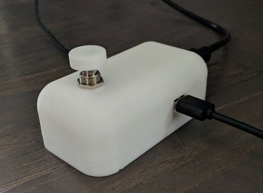
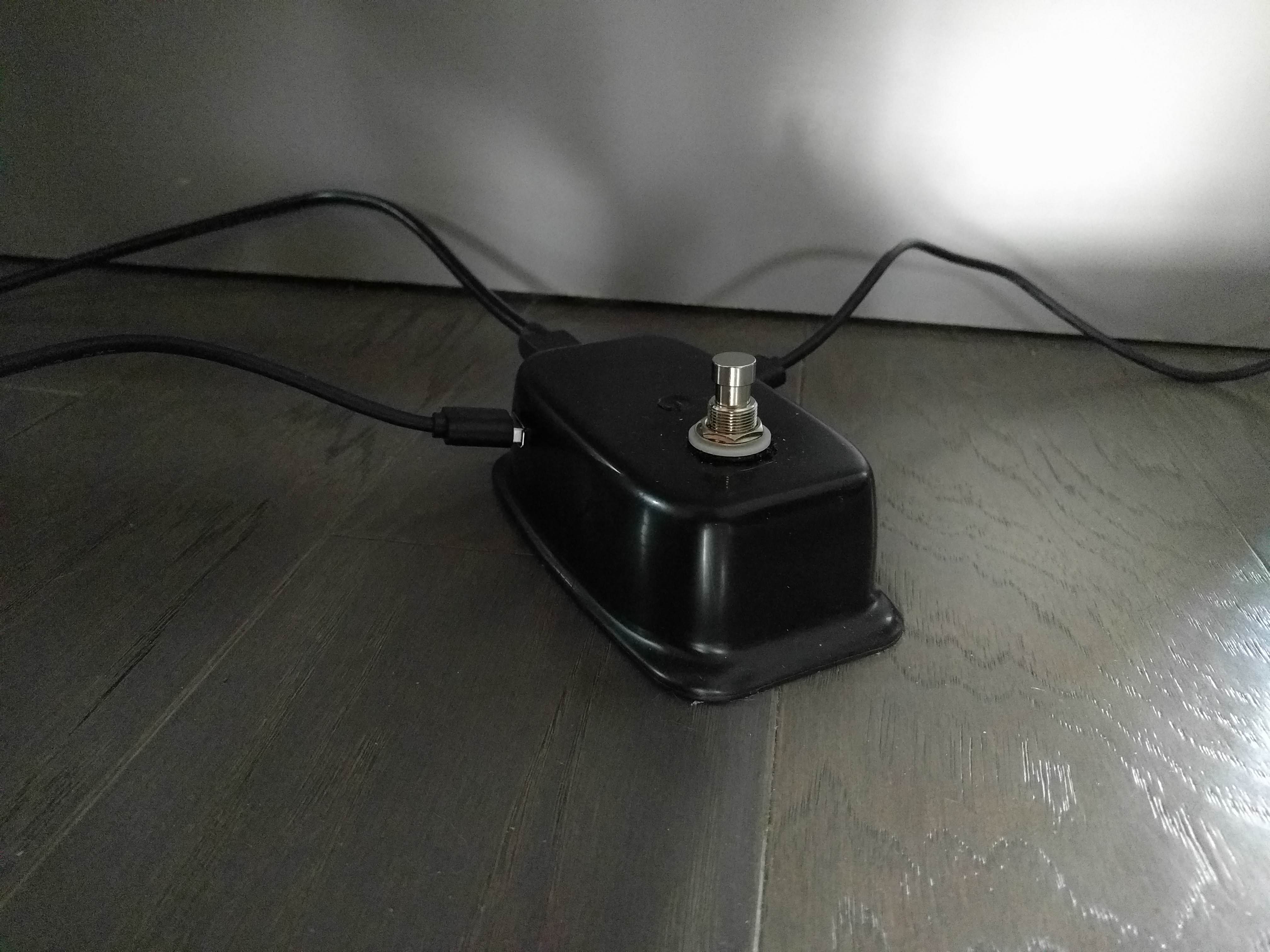
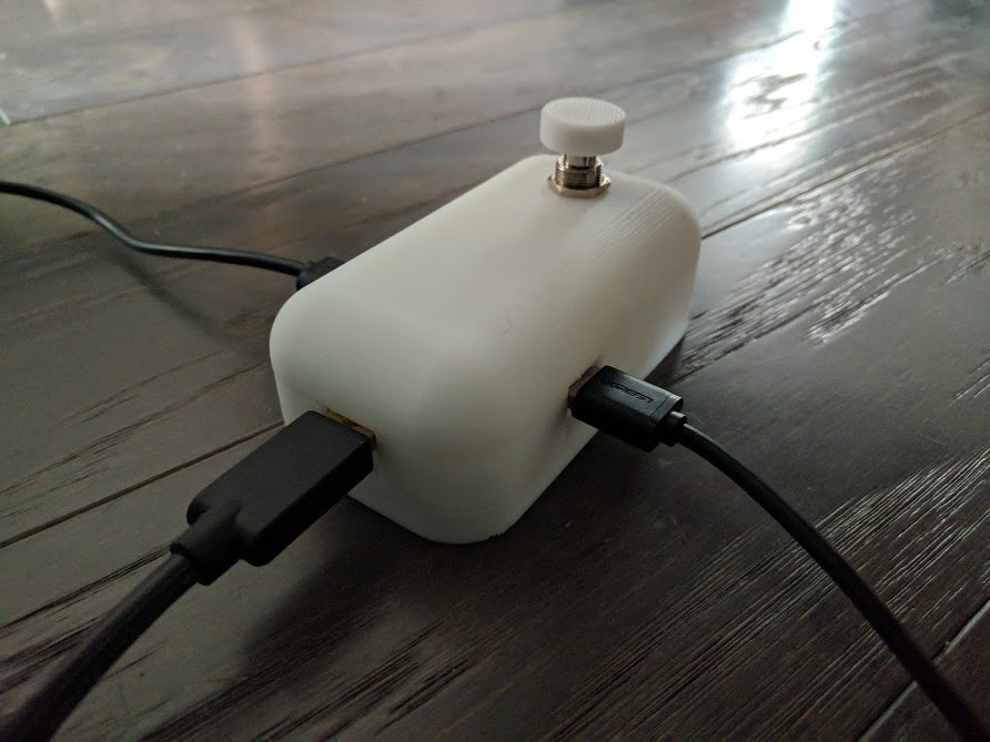
Here it is, in all its glory:
STL files:
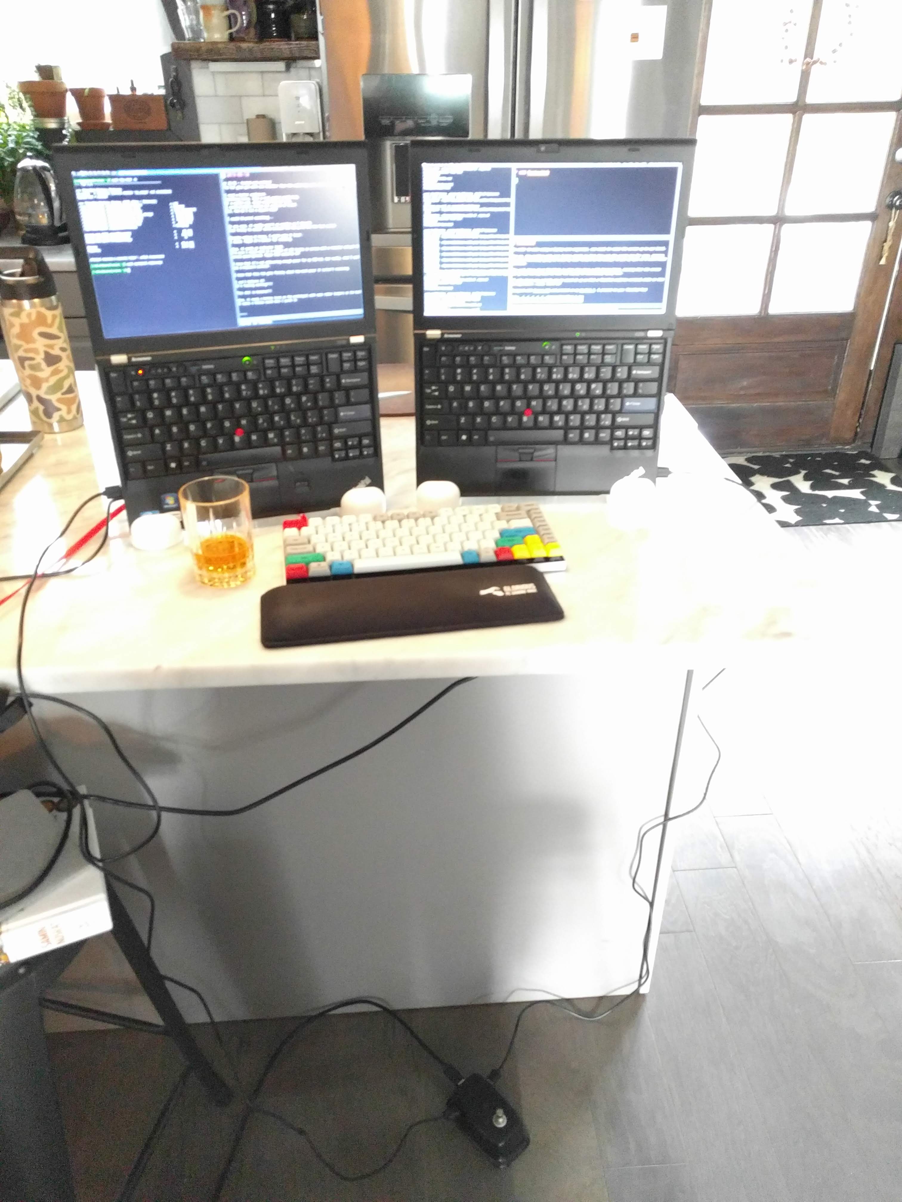
I use several laptops at the same time. They run Linux, OpenBSD, macOS and ChromeOS. I prefer to work on the keyboard blindly and use keyboard navigation. I needed to switch between laptops.
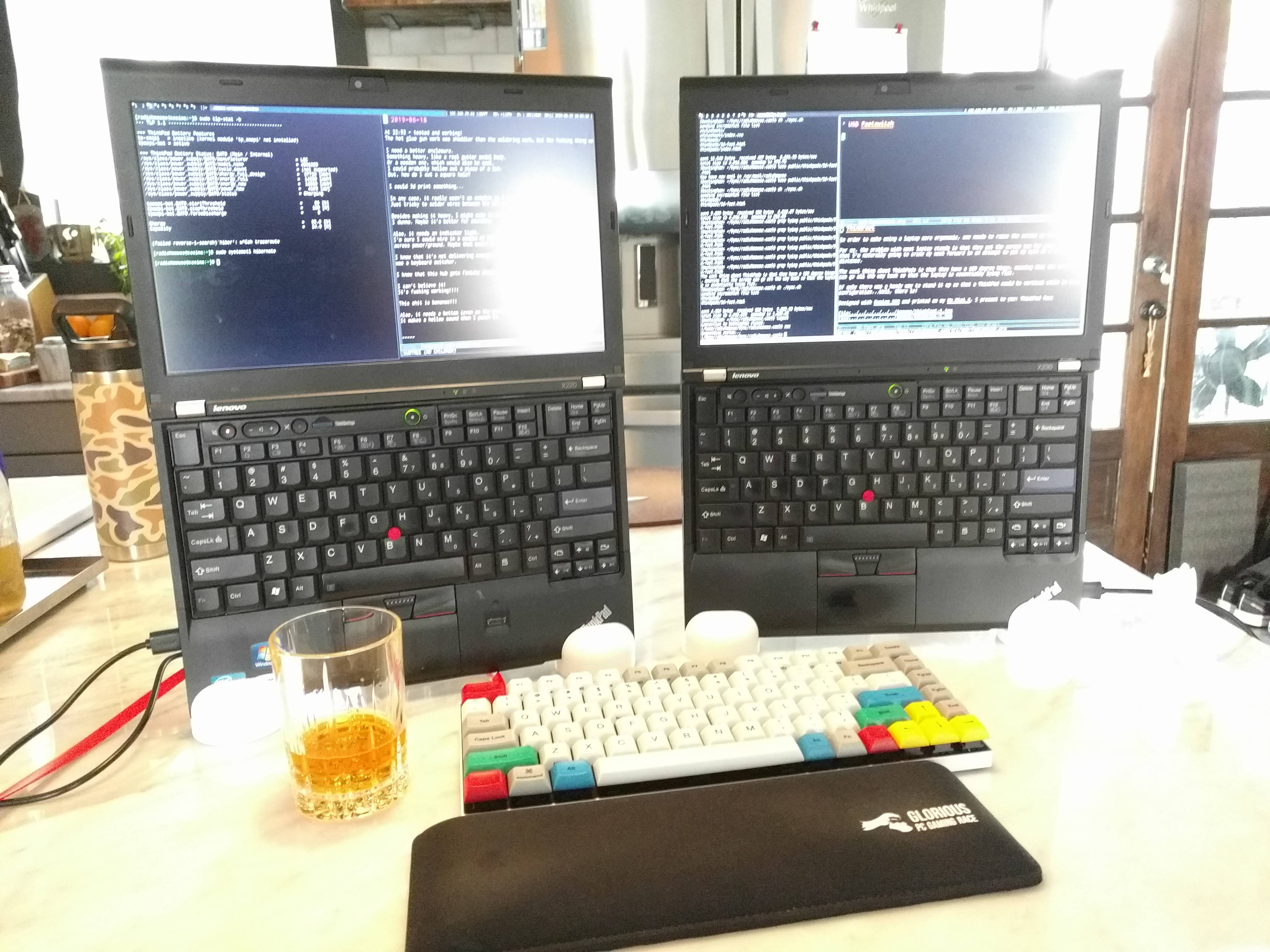
And I wanted to do this without removing my hands from the keyboard. What to do? Tinkering!
Parts List
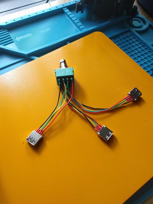
The "circuit" does little - it's just four wires between which there is a switch. The principle of operation of USB is not used.
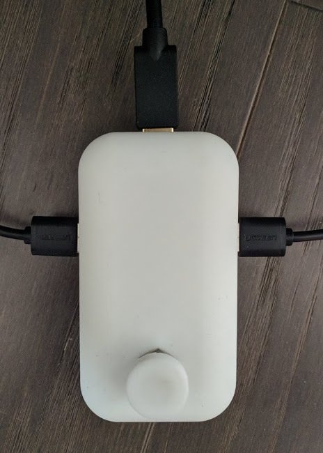
The USB cable coming out from above goes to the keyboard. The other two go each to their computer.
I knew what it meant to be a "universal serial bus," but I did not fully understand. Recently, I have been studying analog electronics. Learning is progressing slowly, but there is progress. One of the topics studied is sequential communication .
And although this is not taken into account in the pedal circuit when I found out that USB is just one of the serial bus options, it removed the magic cover from USB - because of which it becomes magical for a completely different reason. Because now I feel like a wizard.
For USB rev. 1.1 and 2 wires are located as follows:
In theory, I only need D + and D- wires, but then I would have to come up with a separate keyboard power supply. And it was much more difficult than just finding a switch that supports four wires.
Switches are a cool thing. I will no longer take them for granted. Imagining a switch, I usually thought that it opens the circuit or closes, as shown in the diagram from electronicshub.org :

But I needed more than that. I needed to switch four wires for the USB keyboard at a time. And I did not need to disconnect any of the four wires. I needed to:
Impossible? Not at all.
Such a switch that I imagined (like a light switch in a room) is known as a single pole, one direction [Single Pole, Single Throw - SPST].
Here is a chart for it from sparkfun.com:

And I needed a 4PDT switch - four poles (4 wires), two directions (switching between two positions), as in the following diagram:

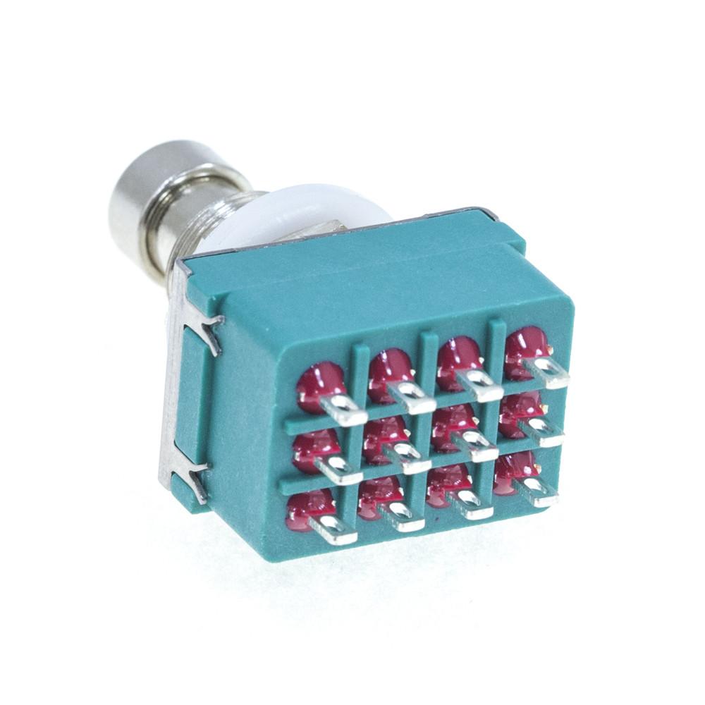
It turned out that this is a very common option used ... in guitar pedals! (remember, I said that I did not want to take my hands off the keyboard).
Here I ordered such a switch with mammothelectronics.com :
Note on guitar pedals: it is important that the switch is latched. This means that it remains connected when you lift your foot. This is important because it would be inconvenient to keep your foot on the pedals constantly so that the keyboard works with a specific computer.
Yes. For the prototype, I took a paste jar and cut holes in it. And, yes - this hot melt adhesive holds USB ports.

Here. So. All. Simply.
And also ugly and fragile. The prototype "worked", but it could not stand daily use. Also, computers sometimes did not recognize the keyboard, and I had to switch back and forth several times.
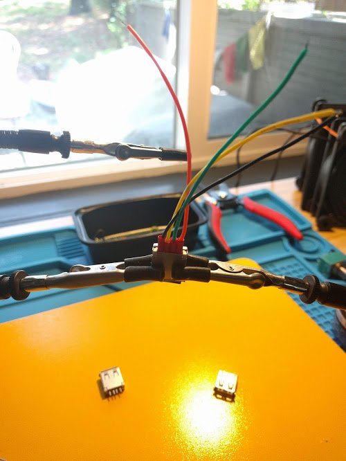
During the manufacturing process of this circuit, a myriad of USB ports suffered. But in the process, I pumped soldering skills great. In the process of soldering tiny wires to tiny contacts, the third-hand system with magnetic grips helped a lot.
After a couple of approaches, I got smarter and started using heat shrink so that my lumps of solder do not touch each other (due to vibrations when I press the pedal).
Yes Yes. Very "professional".
Also recently I have been studying 3D modeling and printing. One of the main principles I have learned is that if you need to print out details that match each other, it is not enough to measure them with a caliper. You also need to print trial details to make sure that they match in reality.
I had to torment them, especially because I did not know why these small metal pins were needed at the end of the ports. It turned out that they are holding plastic in a metal sleeve.
At first I tried to use them to hold the port in the connector - in the next photo you can see them, on both sides of the contacts:
Then I tried to put a cable into this port, and you know what? I squeezed the inner plastic port case out of the metal case.
Well, nothing, you can just make a narrowing there, and this will not happen again.
I thought to cheat and leave the case open from the bottom. So that you can change these cheap USB ports when they break (and I expected this to happen all the time). However, this decision turned out to be bad; open wires are a great way to break solder or destroy contacts.
Knowing that he would still have a bottom, I concentrated on the upper part of the hull, because I needed to determine:
In the photo, the upper left does not have a constriction that prevents ports from being pushed through. The one on the bottom left turned out to be good, but it did not have holes for attaching the bottom.
The model on the right has screw holes. And so I prepared for the design and printing of the bottom of the hull.
I decided not to bother - a simple bottom, with screw holes matching the ones on the top. Yes, and add recesses so that the screws go flush.
I would like for me to have a video of my attempts at 3D modeling. If you are familiar with CAD systems, then you will understand from the text how clumsy the approach I have chosen.
I squeezed the entire bottom out of the main building, and then made a 0.5 mm cutout to separate the bottom from it. It was crooked, but the result yielded. In general, my 3D modeling skills can be described as follows:
And that’s it. That’s all I know how to do. Okay, I also know how to make rounded corners from straight lines and grooves. Seriously, the way I simulate is like trying to light a fire when you throw one stone at another, in the hope that sparks will appear that fall onto the branches.
Problems with the printer were resolved with a long setup and edits. At first, I started to get bad results (from small curvatures to a complete lack of grip on the table). Therefore, the quality of the parts varied from acceptable to comical.

After manually adjusting the table level and nozzle height, I switched to using a perforated substrate (so that the raft was partially connected to the table) and set the table to be preheated for at least 15 minutes. Success! Flat rafts, no distortions.
Port locations were too high, dirt could get there. I don’t think it will hurt, but dirt is bad (the pedal is on the floor, and we have cats).
I added the columns included in the slots so that they held the USB ports and covered the holes.
For some reason, it seemed to me a good idea to make “wells” in the upper part of the building. I don’t think they will help or disturb me, so I left them.
I downloaded and printed the button cover so that it would be convenient to use both in shoes and without.
Success! I use the device daily and it gives me joy. And since I spent time carefully soldering, the contacts turned out to be reliable enough so that I could use a USB hub to connect ... a mouse. Well, you know, if you really need it straight.
Potential improvements may include:
Here it is, in all its glory:
STL files:
Why did i do it
I use several laptops at the same time. They run Linux, OpenBSD, macOS and ChromeOS. I prefer to work on the keyboard blindly and use keyboard navigation. I needed to switch between laptops.
And I wanted to do this without removing my hands from the keyboard. What to do? Tinkering!
Parts List
- 3 USB-A ports (mother).
- 2 USB-A cables (male to male).
- 1 USB extension cable.
- 1 latching 4PDT switch .
- Mounting wire.
- Solder.
- Shrink.
- A bag of plastic for a 3D printer.
Scheme
The "circuit" does little - it's just four wires between which there is a switch. The principle of operation of USB is not used.
The USB cable coming out from above goes to the keyboard. The other two go each to their computer.
A bit about USB
I knew what it meant to be a "universal serial bus," but I did not fully understand. Recently, I have been studying analog electronics. Learning is progressing slowly, but there is progress. One of the topics studied is sequential communication .
And although this is not taken into account in the pedal circuit when I found out that USB is just one of the serial bus options, it removed the magic cover from USB - because of which it becomes magical for a completely different reason. Because now I feel like a wizard.
For USB rev. 1.1 and 2 wires are located as follows:
- 5V (power)
- D + (receiver)
- D- (transmitter)
- GND (ground)
In theory, I only need D + and D- wires, but then I would have to come up with a separate keyboard power supply. And it was much more difficult than just finding a switch that supports four wires.
About switches
Switches are a cool thing. I will no longer take them for granted. Imagining a switch, I usually thought that it opens the circuit or closes, as shown in the diagram from electronicshub.org :
But I needed more than that. I needed to switch four wires for the USB keyboard at a time. And I did not need to disconnect any of the four wires. I needed to:
- 4 wires were connected to computer A.
- When I press the switch, these four wires connect to computer B.
- After clicking again, they reconnect to computer A.
Impossible? Not at all.
Such a switch that I imagined (like a light switch in a room) is known as a single pole, one direction [Single Pole, Single Throw - SPST].
Here is a chart for it from sparkfun.com:
And I needed a 4PDT switch - four poles (4 wires), two directions (switching between two positions), as in the following diagram:
It turned out that this is a very common option used ... in guitar pedals! (remember, I said that I did not want to take my hands off the keyboard).
Here I ordered such a switch with mammothelectronics.com :
Note on guitar pedals: it is important that the switch is latched. This means that it remains connected when you lift your foot. This is important because it would be inconvenient to keep your foot on the pedals constantly so that the keyboard works with a specific computer.
Prototype: paste jar
Yes. For the prototype, I took a paste jar and cut holes in it. And, yes - this hot melt adhesive holds USB ports.
Here. So. All. Simply.
And also ugly and fragile. The prototype "worked", but it could not stand daily use. Also, computers sometimes did not recognize the keyboard, and I had to switch back and forth several times.
Correct soldering
During the manufacturing process of this circuit, a myriad of USB ports suffered. But in the process, I pumped soldering skills great. In the process of soldering tiny wires to tiny contacts, the third-hand system with magnetic grips helped a lot.
After a couple of approaches, I got smarter and started using heat shrink so that my lumps of solder do not touch each other (due to vibrations when I press the pedal).
Yes Yes. Very "professional".
3D housing modeling
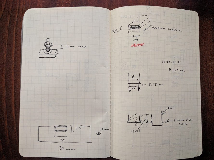
Also recently I have been studying 3D modeling and printing. One of the main principles I have learned is that if you need to print out details that match each other, it is not enough to measure them with a caliper. You also need to print trial details to make sure that they match in reality.
USB Port Connectors
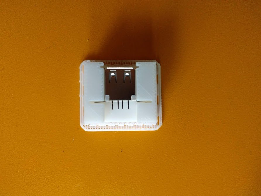
I had to torment them, especially because I did not know why these small metal pins were needed at the end of the ports. It turned out that they are holding plastic in a metal sleeve.
At first I tried to use them to hold the port in the connector - in the next photo you can see them, on both sides of the contacts:
Then I tried to put a cable into this port, and you know what? I squeezed the inner plastic port case out of the metal case.
Well, nothing, you can just make a narrowing there, and this will not happen again.
Main building
I thought to cheat and leave the case open from the bottom. So that you can change these cheap USB ports when they break (and I expected this to happen all the time). However, this decision turned out to be bad; open wires are a great way to break solder or destroy contacts.
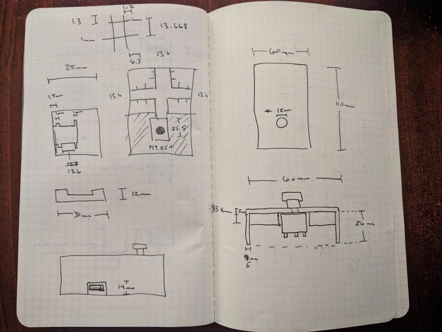
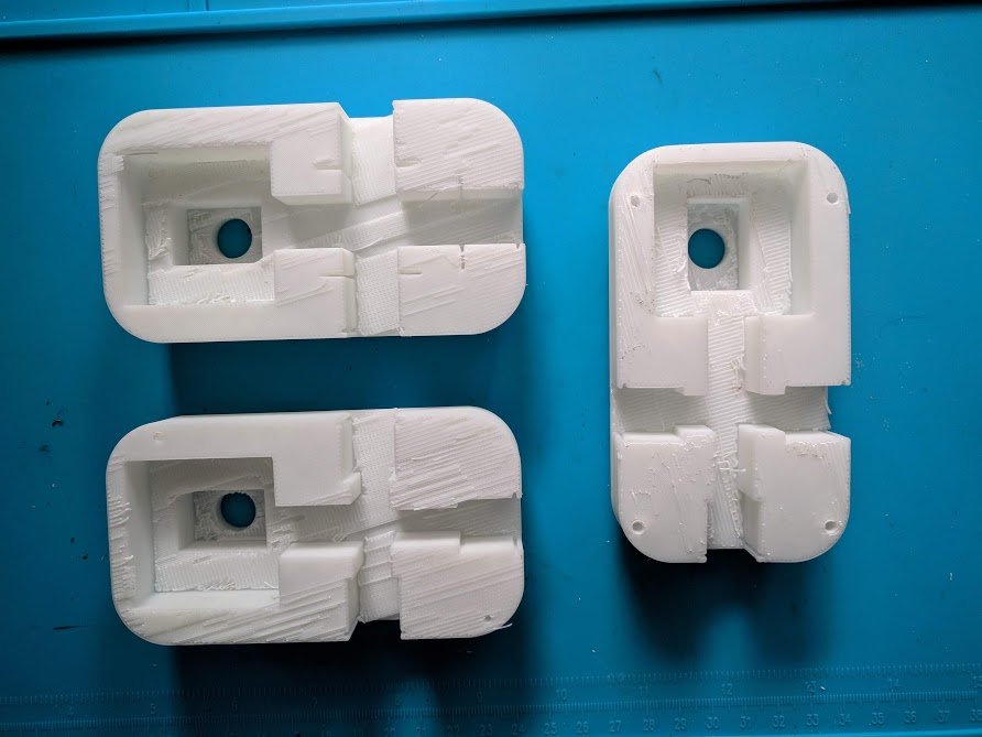
Knowing that he would still have a bottom, I concentrated on the upper part of the hull, because I needed to determine:
- Will she hold the ports and switch in place?
- Is it tall enough to fit wires from the switch?
In the photo, the upper left does not have a constriction that prevents ports from being pushed through. The one on the bottom left turned out to be good, but it did not have holes for attaching the bottom.
The model on the right has screw holes. And so I prepared for the design and printing of the bottom of the hull.
Bottom
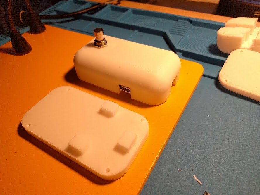
I decided not to bother - a simple bottom, with screw holes matching the ones on the top. Yes, and add recesses so that the screws go flush.
If you have a hammer in your hands ...
I would like for me to have a video of my attempts at 3D modeling. If you are familiar with CAD systems, then you will understand from the text how clumsy the approach I have chosen.
I squeezed the entire bottom out of the main building, and then made a 0.5 mm cutout to separate the bottom from it. It was crooked, but the result yielded. In general, my 3D modeling skills can be described as follows:
- Draw rectangles and circles.
- Push / pull.
And that’s it. That’s all I know how to do. Okay, I also know how to make rounded corners from straight lines and grooves. Seriously, the way I simulate is like trying to light a fire when you throw one stone at another, in the hope that sparks will appear that fall onto the branches.
Problems with the printer were resolved with a long setup and edits. At first, I started to get bad results (from small curvatures to a complete lack of grip on the table). Therefore, the quality of the parts varied from acceptable to comical.
After manually adjusting the table level and nozzle height, I switched to using a perforated substrate (so that the raft was partially connected to the table) and set the table to be preheated for at least 15 minutes. Success! Flat rafts, no distortions.
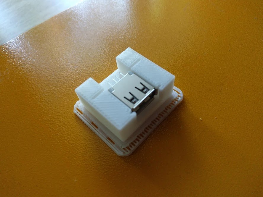
Add support for USB ports
Port locations were too high, dirt could get there. I don’t think it will hurt, but dirt is bad (the pedal is on the floor, and we have cats).
I added the columns included in the slots so that they held the USB ports and covered the holes.
For some reason, it seemed to me a good idea to make “wells” in the upper part of the building. I don’t think they will help or disturb me, so I left them.
More ergonomic button cover
I downloaded and printed the button cover so that it would be convenient to use both in shoes and without.
Conclusion
Success! I use the device daily and it gives me joy. And since I spent time carefully soldering, the contacts turned out to be reliable enough so that I could use a USB hub to connect ... a mouse. Well, you know, if you really need it straight.
Potential improvements may include:
- Rubber gasket bottom.
- LED backlight indicating which side is currently operating.
- Hydraulics.
- Subwoofer
All Articles