FLProg - Independent integration into the program of custom controllers
For a long time the FLProg project has not been covered in Habré. This is due to the lack of time for writing articles, and even my own personal problems. But the project is not dead, it lives and develops. On average once a month, the next version of the program is released. Since the last publication , the rendering of the circuit has been completely redone (thanks to this, friezes were eliminated during the rendering), the Cross Reference system for the project, and a system for analyzing the project for errors, appeared. Directly the program code itself was ported to a more recent version of the programming language. Due to this, in a positive (from my point of view, of course, well, users support me) side, the program interface has changed. Many interesting blocks have been added. Implemented scheme scaling and block search.
But still, the main problem of the project remains that the developer of the program is one person (this is me), and the number of different controller boards, sensors, sensors, expansion cards manufactured both by Chinese and recently by our manufacturers is constantly growing. And users want to try them, or use them in their projects. For peripheral devices, at one time, this problem was more or less solved by me with the help of creating a custom block editor. This step, as they say, “shot”, and now, almost on most existing peripheral boards, on the Internet, or on the program’s forum , you can find the corresponding user block. Well, or at the same forum (or in a group in Vkontakte ) ask the local gurus to write one. Usually you can one way or another agree.
Now it's time to solve the second problem - these are controller boards.
Recently, a beta version of the program with the number 6.0 was released. In this version, the editor for user descriptions of controllers is implemented. As with custom blocks, descriptions can be grouped into libraries, saved as separate descriptions as well as entire libraries as a file, and shared.
With this post, I begin a series of at least two posts in which we will consider how to use this editor. In the first article, with the permission of shiotiny, I will try to describe his ShIoTiny board. In the second article, we will try to virtually come up with an analog of a real industrial controller, and describe it.
So, let's begin.
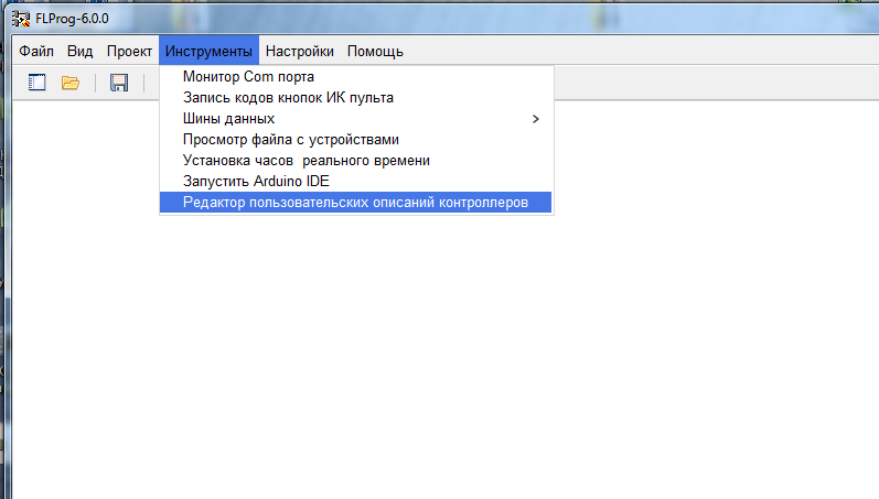
Open the FLProg program. In the "Tools" menu, select the "Controller Custom Descriptions Editor".
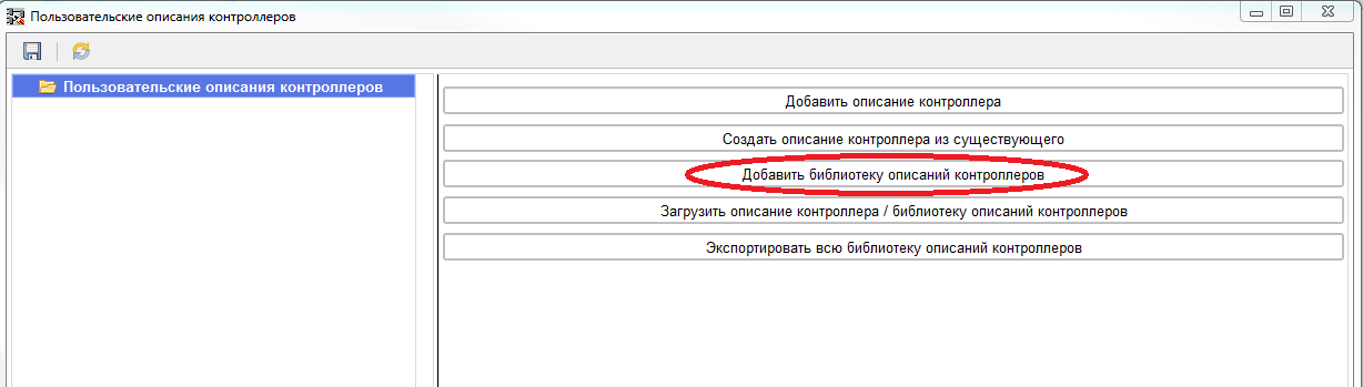
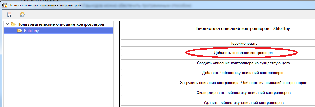
The description editor window opens.
Custom descriptions can be combined in the library with any nesting depth. Therefore, we first create a description library.
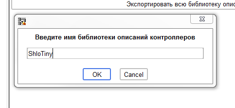
Set the name of the library.
Then we will create the controller description in the library.
And give him a name:
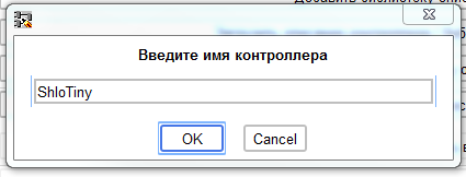
When creating the controller description, we immediately get to the branch of general parameters.
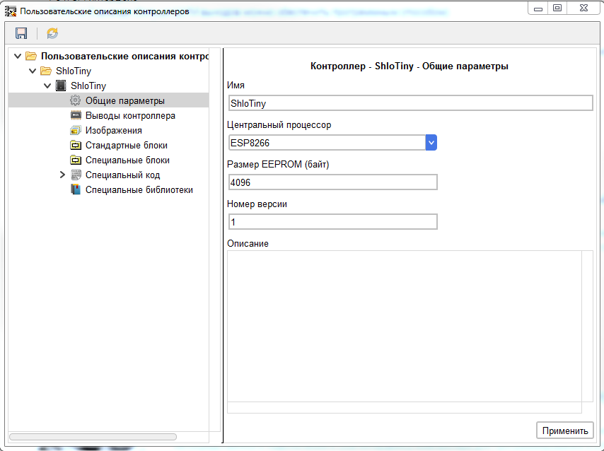
Here we can change the name, set the type of CPU, set the size of the EEPROM, change the version number of the description.
Since the ShloTiny board is based on the ESP8266 controller, we select it. When choosing a controller, the corresponding EEPROM volume is automatically affixed. If necessary, this value can be changed. The default version number for the new description is set to 1.
In the future, when changing existing descriptions, it is recommended to change it in the direction of increase. When using this description in the project, the program will compare the version of the description in the project and in the library. If the version number of the description in the library is greater than in the project, an item will appear in the "Project" menu of the program to update the description in the program. If vice versa, then an item will appear to update the description in the library. Well, if the description of the controller used in the project is not found in the library at all, the item for entering the description from the project into the library will appear in the same menu.
Also in this thread, you can write a text description of the controller that helps with its selection.
To apply the changes made before changing to another branch of the controller parameters, click the "Apply" button. If this is not done, the changes will not be saved.
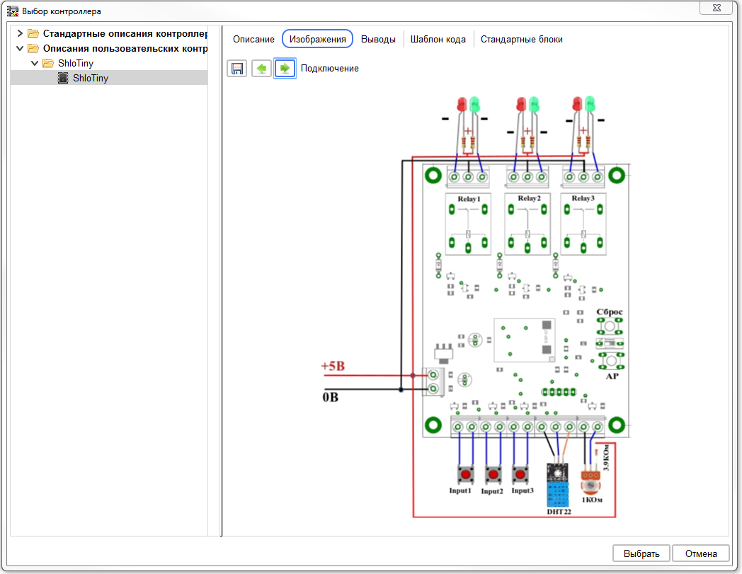
Now consider the circuit diagram of the ShloTiny board.
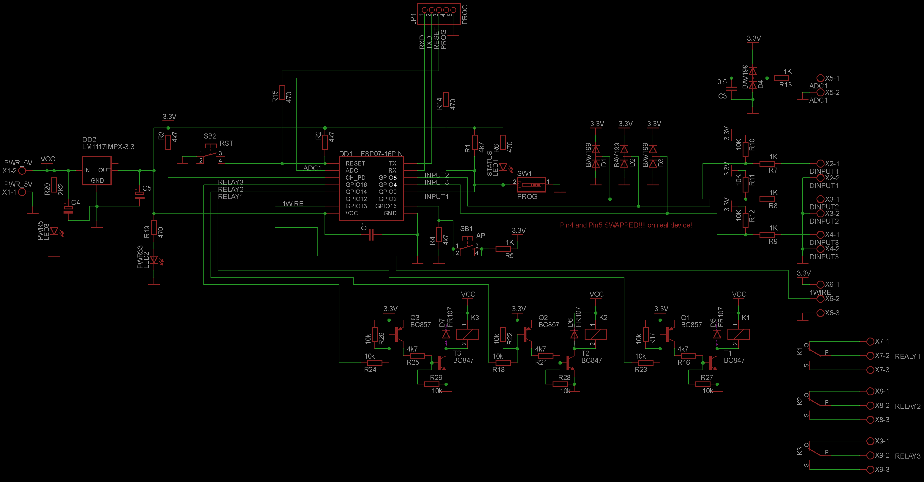
The board has three digital inputs, three digital outputs, an analog input, and an input for the sensor. A total of eight conclusions of the board.
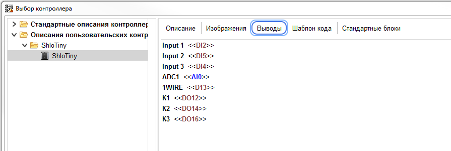
In the editor, go to the “Controller conclusions” branch and set the number of conclusions, do not forget to click the “Apply” button after that.
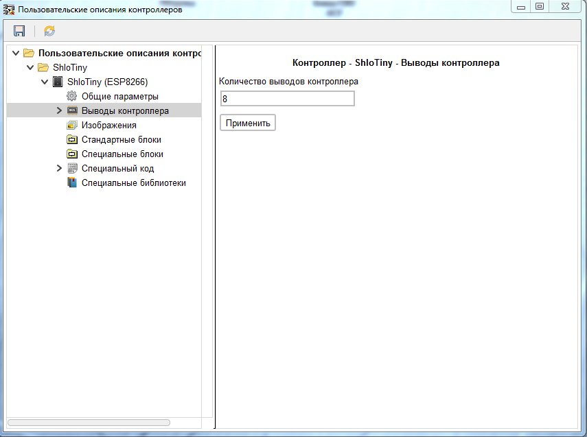
The program will generate the required number of conclusions. We pass to the first of them.
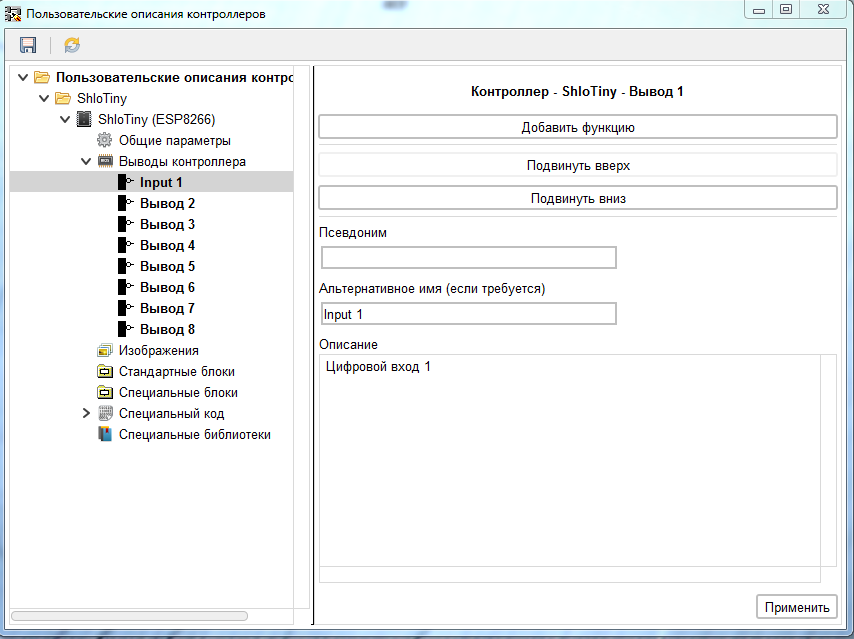
On this branch, you can specify an alternative output name, which will be displayed in the program. If it is absent, the program will display PinN where N is the pin number in the pin list. I recommend that you write an inscription to it on the board in the alternate name field. This will make it easier to understand what conclusion is being drawn. For the described board, we will enter the value of Input1 there in accordance with the circuit diagram. So in this thread you can write an individual description of the output, for example, to indicate the features of its application. If necessary, you can also specify an alias for the output, which will be displayed in the program in brackets after the name of the output.
After making the changes, do not forget to click the "Apply" button. By the same principle, let us call the remaining conclusions.
In the same branch of the main output parameters, the functions it performs are added to it.
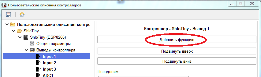
The following functions can be assigned to each pin.
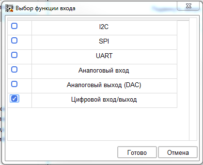
- I2C is a function of one of the I2C bus pins (SDA or SCL).
- SPI is a function of one of the SPI bus pins (MISO, MOSI, SCK, SS).
- UART is a function of one of the pins of the UART interface (RX or TX).
- Analog input function
- Analog output function (not yet used in FLProg, backlog for the future).
- Digital input / output function.
Assign pin 1 digital input / output function. When assigning a new function (not yet configured) to the output, the “Errors” branch will appear in the controller tree and the entire path to the branch of the incorrect function will turn red. On the "Errors" branch, you can see a list of errors found in the controller description.

In this case, input 1 in the Digital Input / Output function does not specify the number of this input as digital. We switch to the branch of this function (in the future I plan to make a direct transition to the desired branch when I click on an error).

According to the circuit diagram of the board, the output “Input1” is connected to the GPIO2 pin of the controller. We enter this value in the “Digital input number” field. When compiling a project, this value will be inserted into the code. Since the use of this input as an output is not provided, we remove the checkbox “Can be used as an output”. As always, click the "Apply" button. In the same way, configure the other two digital inputs. Then go to the output of the analog input "ADC1" and add the function "Analog Input" to it.
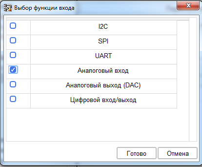
In the settings of this function, you must specify the number of this output as an analog input. According to the scheme, this is 0 (in ESP8266 it is one).

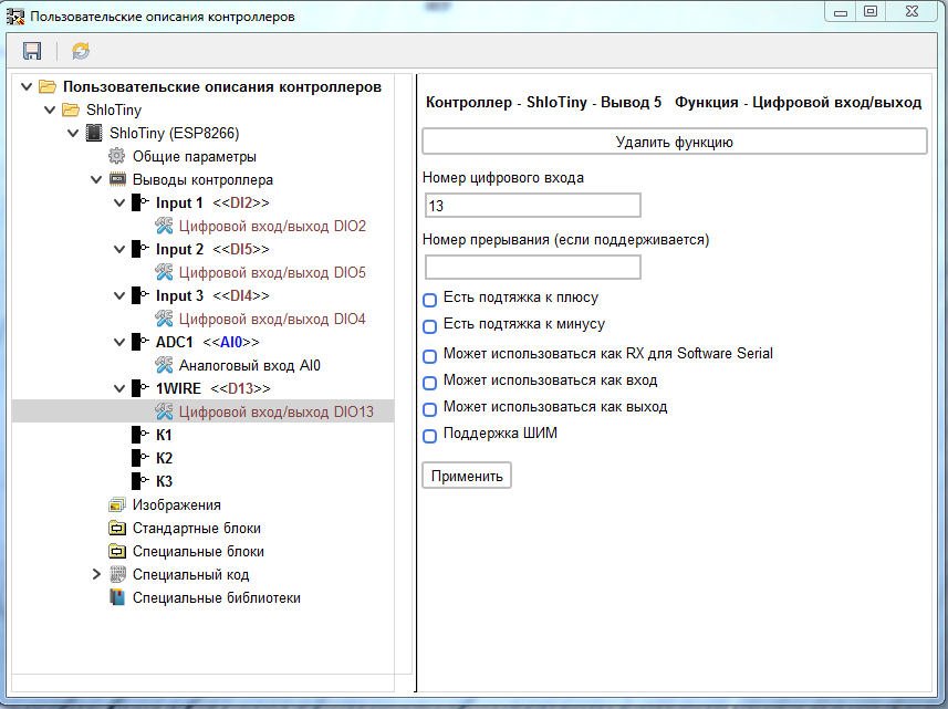
Then go to the output setting "1WIRE". Here we add the digital input / output function to it, but we prohibit its use of both input and output. As a result, it will be available for selection only in the sensor blocks, and is not available when creating inputs and outputs.
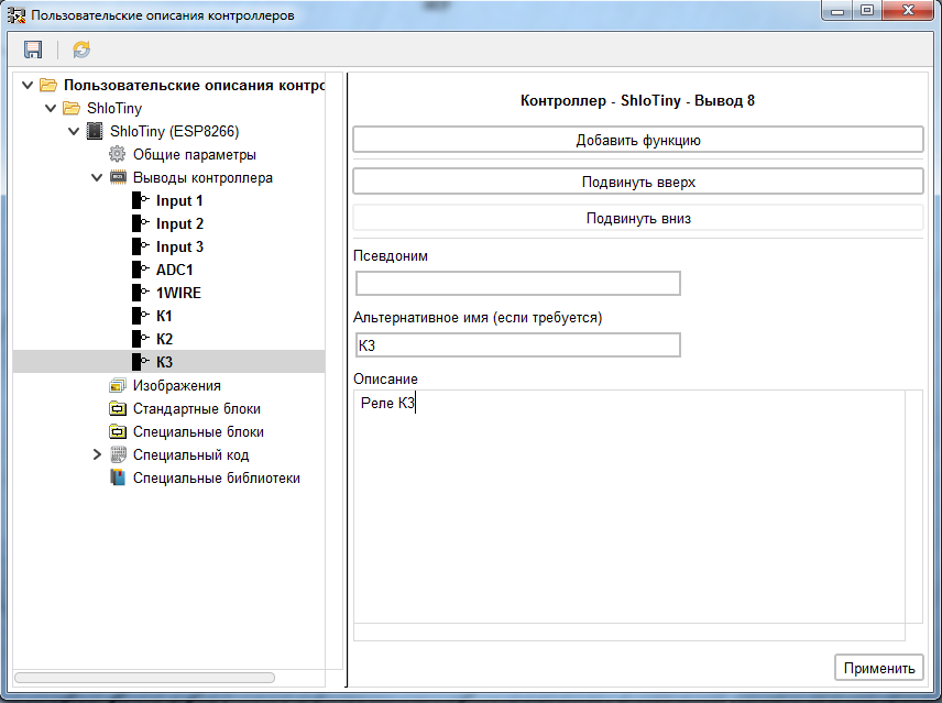
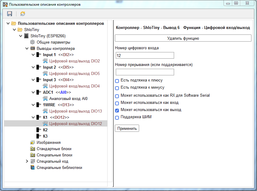
The settings of the outputs “K1” - “K3” are similar to the settings of the inputs “Input1” - “Input3” only in case of outputs we forbid them to be used as an input.

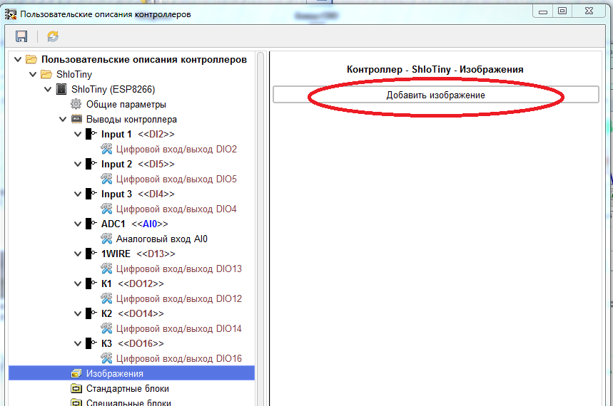
Go to the "Images" branch. In it, we can add images loaded into the description of the controller, for example, with the appearance of the controller, pinout, etc.
Please note that images are loaded directly into the controller description, and it is stored in a project created using it. Therefore, do not upload large images. This will entail an increase in the size of the project, and will affect the speed of its opening.
The image is added using the “Add Image” button.
After selecting and loading an image (only PNG format is supported), a separate branch is created for each image in the tree. In this branch, you can specify a name for the downloaded image, which will be displayed in the controller information.
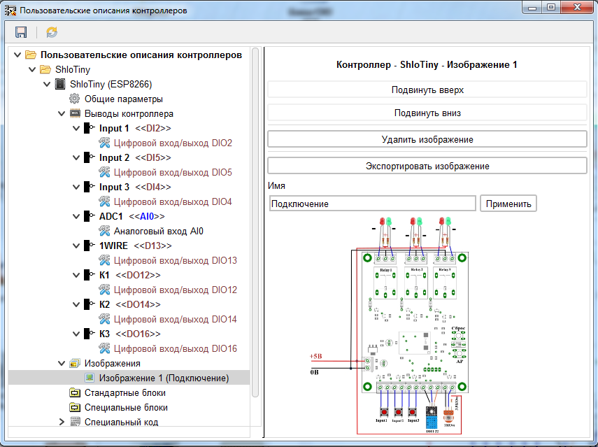
If necessary, you can upload several images and put them in the desired order.


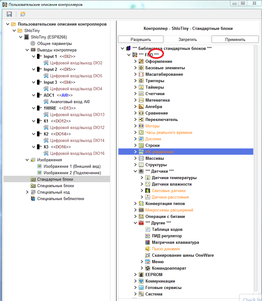
We pass to the branch "Standard blocks".
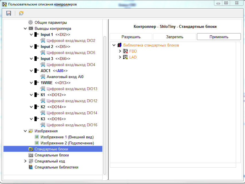
This branch shows blocks that can be represented in the library of standard blocks of the program in accordance with the current settings of the program. What does it mean. Some of the building blocks of the program are intended only for certain types of CPUs. And their availability depends on the selected processor. Also, blocks designed to work with SPI, I2C, UART will appear in this list only if the corresponding functions are added to the controller pins. Blocks designed to work with the EEPROM will appear only if the EEPROM size specified on the branch of the general controller parameters is greater than zero, or the I2C function is added to the controller pins. By default, all blocks in the library are prohibited for use (marked in orange). You can allow for use either a separate block or the entire folder of blocks, highlighting the necessary branch and clicking the "Allow" button, or from the context menu.
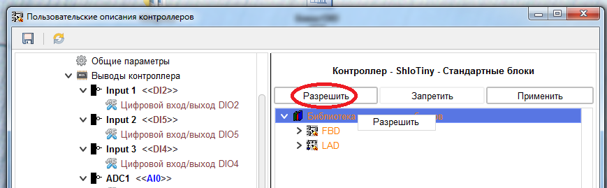
When you allow a block or folder of blocks to be displayed in the program, they are painted black.
The blocking of a block or a separate folder is prohibited in the same way.
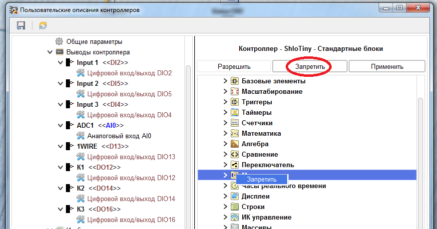
In a folder in which not all blocks are allowed to be displayed, they are marked with three asterisks before and after the name.
We prohibit the use of motors, real-time clocks, displays, IR control units, sensors (except for the DS18B20 and DHT22 sensors, as the board developer has so far only announced their support), expansion chips, and a piezo speaker.
We will do the same for the LAD language

Do not forget to apply them after making changes.
The remaining branches of the controller description will be discussed in the next post, while the current settings are enough to use this board specifically in the FLProg program.
For now, I’ll just briefly say that the “Special Blocks” branch is used to load custom blocks into the description, which will be shown in the library of standard blocks in the program when using this controller. The “Special code” branch is used to record the code that will always be inserted into the compiled code, and the “Special libraries” branch is used to load libraries into the controller’s description, which will be uploaded to the \ libraries ArduinoIDE folder with which the program works.
After all the changes, save the controller description library.
Now let's try to use the controller description that we created.
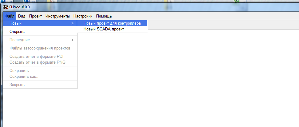
In the FLProg program, we create a new project for the controller.
Open the controller selection window.

And select the description we created.

When choosing a controller, you can see its images and, if necessary, save the necessary to a file.
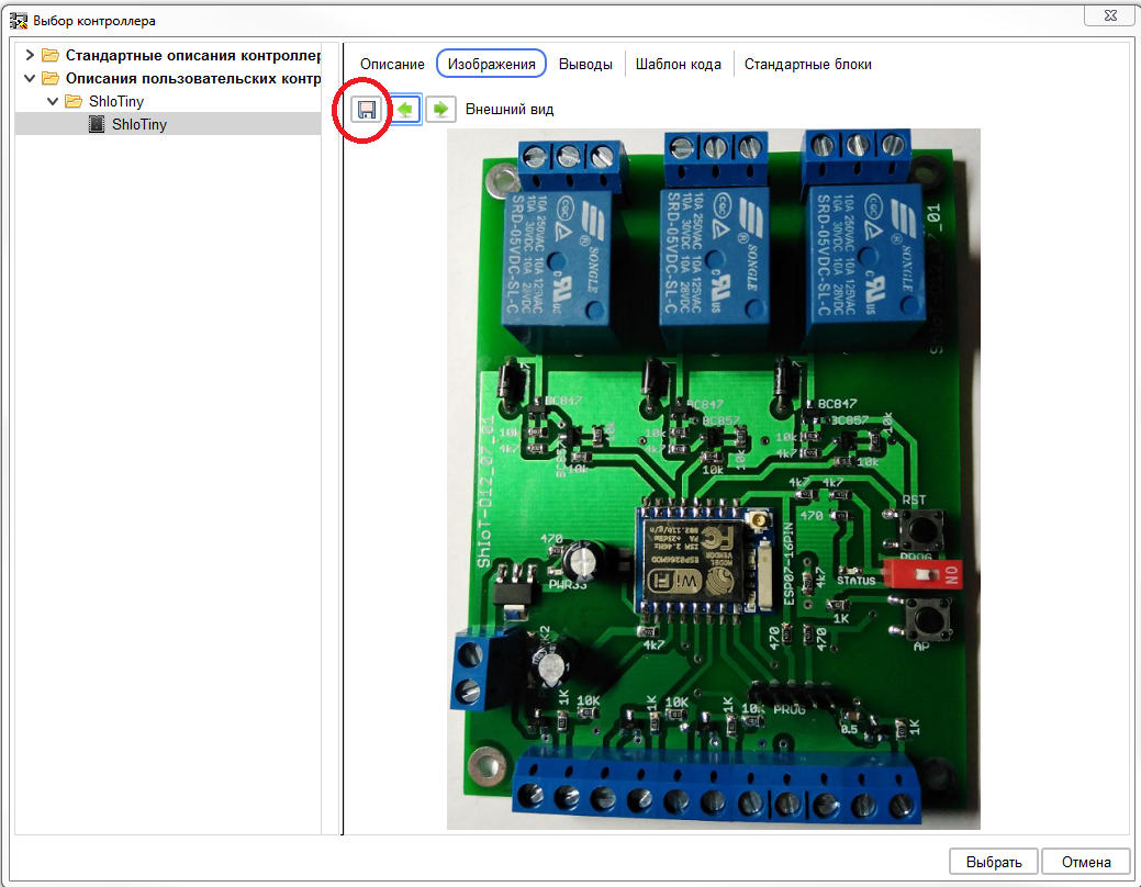
You can also see other parameters
After selecting the controller, confirm its selection:
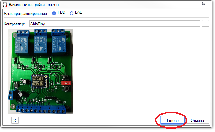
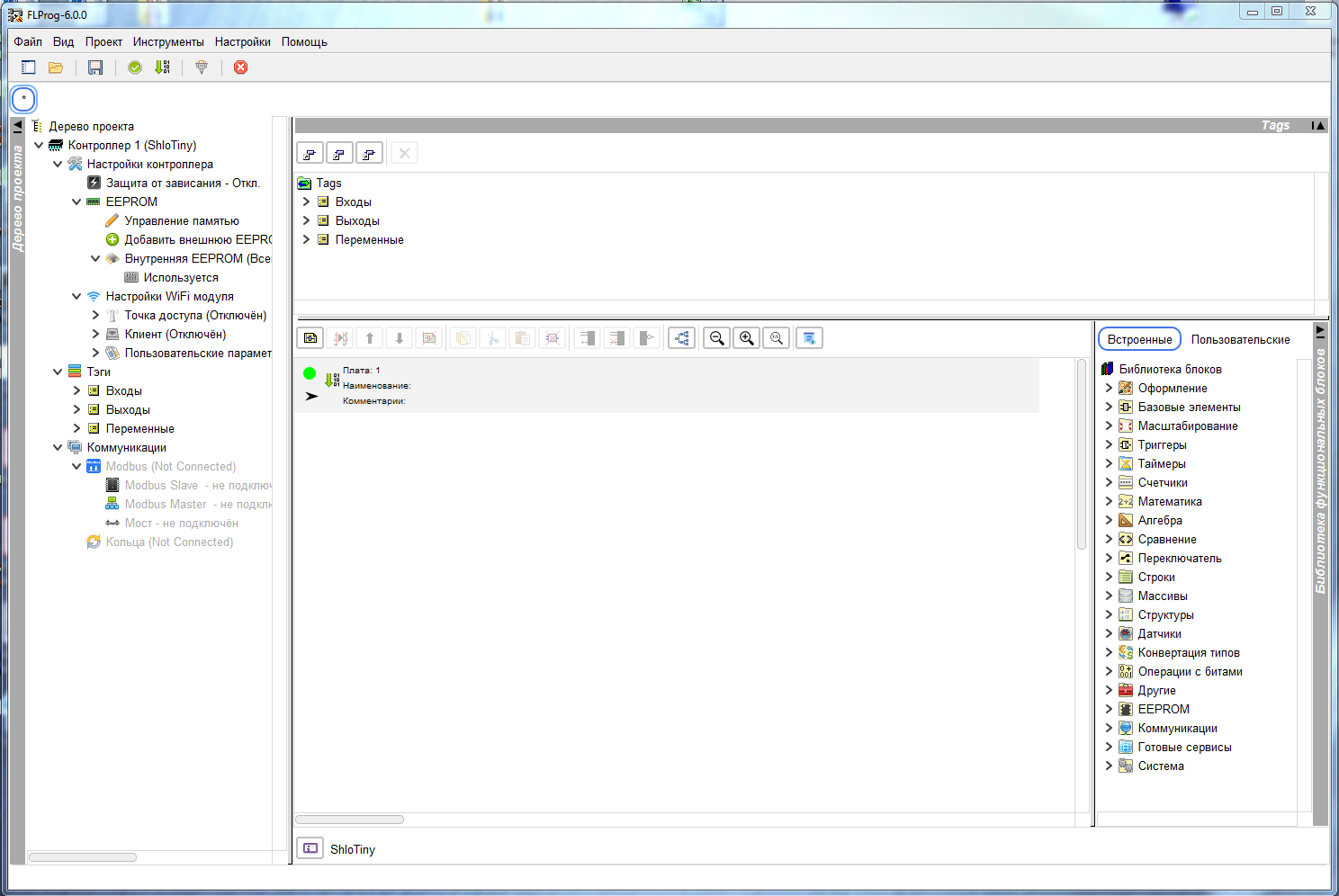
As a result, the main project working window opens, configured in accordance with the selected controller.
The purpose of this post does not include the task of training to work with the FLProg program. This is fairly well described in my previous posts , on the project website , and on the project forum . In addition, there are already quite a lot of channels on YouTube where video tutorials on working with the program are posted. For example, a very good channel, “Key to Arduino,” is just now conducting a series of lessons, with a very good presentation of material.
Therefore, for example, we simply create a simple project and try to compile it.
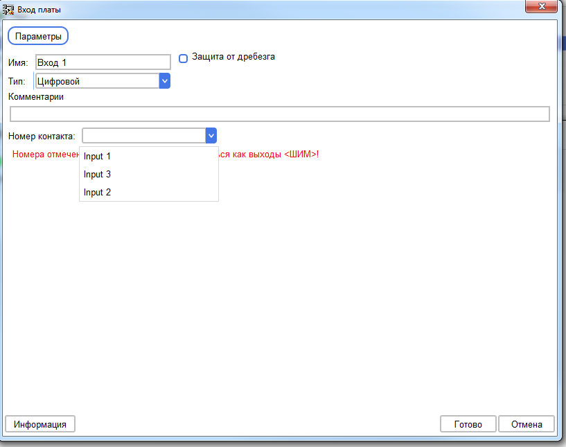
First, add the controller input.
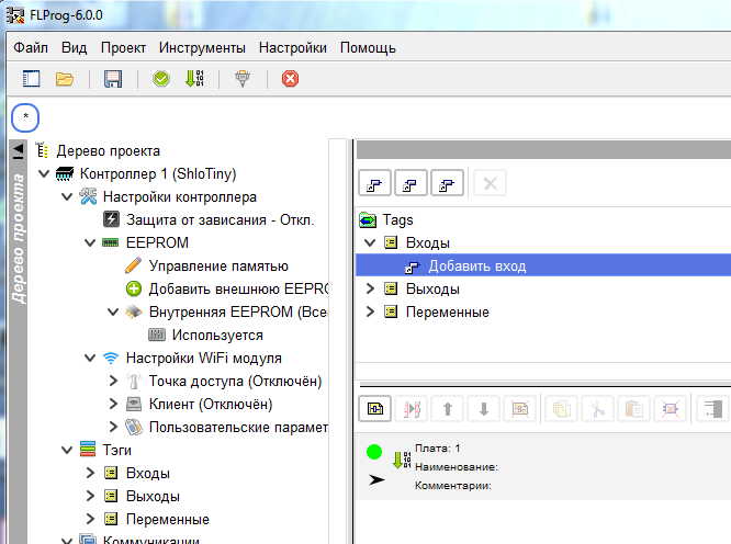
Only those conclusions that we were allowed to work in that capacity are available for selection as an input.
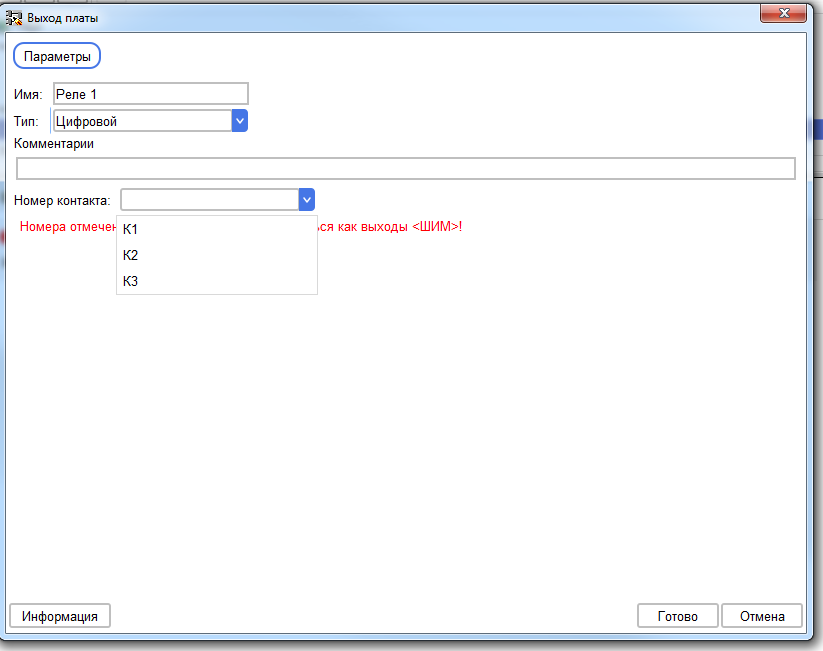
Then create a digital output. Only permitted conclusions are also available here.
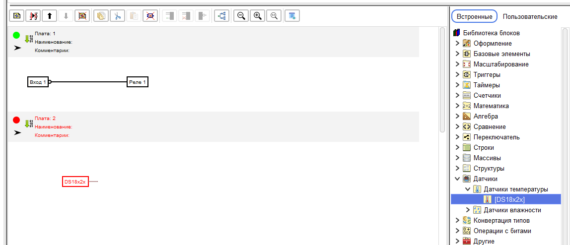
We assemble the circuit so that when the button on Input1 (Input 1) is pressed, relay K1 (Relay1) is turned on.
We also pull out the block for reading information from the DS18B20 sensor onto a circuit in a separate board.
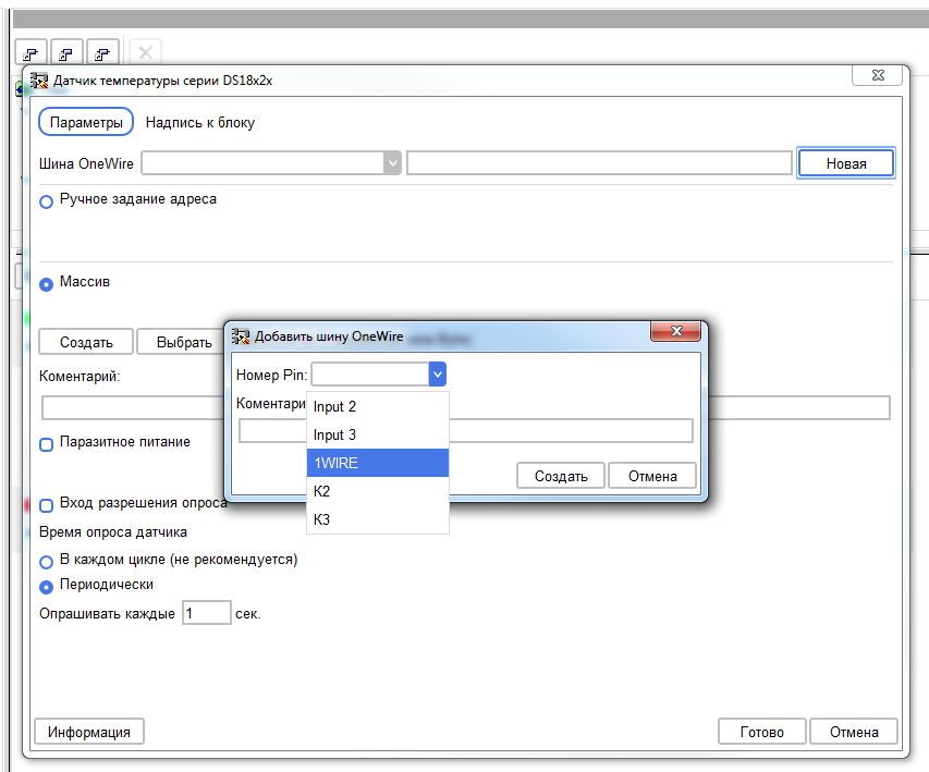
Go to the block settings. When creating the new OneWire bus, we see that all digital inputs / outputs are available for selection. This is a flaw in version 6.0. But since this version still has beta status, it is excusable. In version 6.1, it will be possible to prohibit the use of a pin as a sensor, sensor, or for expansion chips. In addition, in the next post I will tell you another way to solve this problem. For now, select 1WIRE pin.
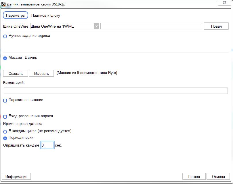
We configure the sensor to set the address through the array.
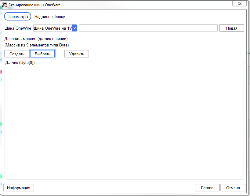
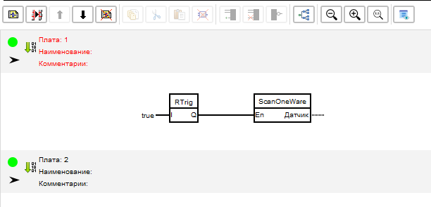
We insert a new board in front of the first one and pull out the “OneWire Bus Scan” block on it.

We configure it on the same OneWire bus, and on the same array, on which the reader unit from the DS18B20 sensor is configured.
We assemble a scheme for a single start of a bus scan when the controller starts, using the trigger block R (selection of the leading edge).
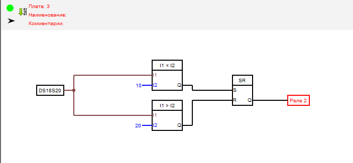
On a board with a data reading unit from the DS18B20 sensor, we assemble a relay on / off circuit with hysteresis. For this, we use two comparators, and an SR trigger. Thanks to this scheme, relay 2 will turn on when the temperature drops below 10 degrees, and turn off when the temperature rises above 20 degrees.
Run the compilation scheme.

As a result, the resulting code will open in the Arduino IDE. As the board, we select NodeMCU, on which the same chip is installed as on ShloTiny. Checking the code shows that it is correct and can be downloaded.

Compiled code
#include <OneWire.h> extern "C" { #include "user_interface.h"; } OneWire _ow13(13); byte _FLPArray133289689[9]; unsigned long _d18x2x1Tti = 0UL; float _d18x2x1O = 0.00; bool _trgr1 = 0; bool _bounseInputD2S = 0; bool _bounseInputD2O = 0; unsigned long _bounseInputD2P = 0UL; bool _trgrt1 = 0; bool _trgrt1I = 0; bool _sowb1_needScan = 0; bool _sowb1_ost = 0; bool _sowb1_Out_1 = 0; void setup() { pinMode(2, INPUT); pinMode(12, OUTPUT); pinMode(14, OUTPUT); _bounseInputD2O = digitalRead(2); } void loop() { bool _bounceInputTmpD2 = (digitalRead (2)); if (_bounseInputD2S) { if (millis() >= (_bounseInputD2P + 40)) { _bounseInputD2O = _bounceInputTmpD2; _bounseInputD2S = 0; } } else { if (_bounceInputTmpD2 != _bounseInputD2O ) { _bounseInputD2S = 1; _bounseInputD2P = millis(); } } //:1 if (1) { if (_trgrt1I) { _trgrt1 = 0; } else { _trgrt1 = 1; _trgrt1I = 1; } } else { _trgrt1 = 0; _trgrt1I = 0; }; if (_sowb1_needScan) { if ( _oneWireSeach (_FLPArray133289689, _ow13)) { _sowb1_Out_1 = 1; } _ow13.reset_search(); _sowb1_needScan = 0; } if (_trgrt1) { if (! _sowb1_ost) { _sowb1_ost = 1; _sowb1_needScan = 1; _sowb1_Out_1 = 0; } } else { _sowb1_ost = 0; } //:2 digitalWrite(12, !(_bounseInputD2O)); //:3 if (_isTimer(_d18x2x1Tti, 1000)) { _d18x2x1Tti = millis(); _d18x2x1O = _readDS18_ow13(_FLPArray133289689, _FLPArray133289689[8]); } if (((_d18x2x1O)) > (20)) _trgr1 = 0; if (((_d18x2x1O)) < (10)) _trgr1 = 1; digitalWrite(14, _trgr1); } bool _isTimer(unsigned long startTime, unsigned long period ) { unsigned long currentTime; currentTime = millis(); if (currentTime >= startTime) { return (currentTime >= (startTime + period)); } else { return (currentTime >= (4294967295 - startTime + period)); } } float _convertDS18x2xData(byte type_s, byte data[12]) { int16_t raw = (data[1] << 8) | data[0]; if (type_s) { raw = raw << 3; if (data[7] == 0x10) { raw = (raw & 0xFFF0) + 12 - data[6]; } } else { byte cfg = (data[4] & 0x60); if (cfg == 0x00) raw = raw & ~7; else if (cfg == 0x20) raw = raw & ~3; else if (cfg == 0x40) raw = raw & ~1; } return (float)raw / 16.0; } float _readDS18_ow13(byte addr[8], byte type_s) { byte data[12]; byte i; _ow13.reset(); _ow13.select(addr); _ow13.write(0xBE); for ( i = 0; i < 9; i++) { data[i] = _ow13.read(); } _ow13.reset(); _ow13.select(addr); _ow13.write(0x44, 1); return _convertDS18x2xData(type_s, data); } bool _oneWireSeach (byte array[], OneWire ow ) { byte temp[8]; byte i; if ( !ow.search(temp)) { return false; } if (OneWire::crc8(temp, 7) != temp[7]) { return false; } switch (temp[0]) { case 0x10: array[8] = 1; break; case 0x28: array[8] = 0; break; case 0x22: array[8] = 0; break; default: return false; } for ( i = 0; i < 8; i++) { array[i] = temp[i]; } return true; }
→ Description of the ShloTiny controller for the FLProg program
We’ll finish this lesson, in the next post we’ll try to describe something more serious and closer to “real” industrial controllers.
All Articles