ShIoTiny and the world: analog sensors or ADCs for the smallest
Key points or what this article is about
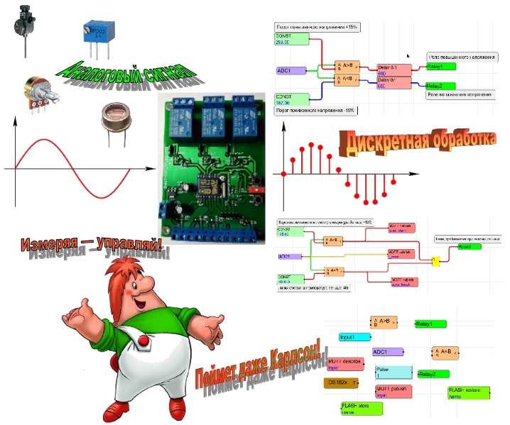
Continuation of a series of articles on ShIoTiny - a visually programmable controller based on the ESP8266 chip. A key feature of this controller is the ability to program it by drawing a program in a browser.
This article describes a brief theory of analog-to-digital conversion and the practical application of the ShIoTiny ADC controller.
Previous articles in the series.
ShIoTiny: small automation, the Internet of things, or “six months before the holidays”
ShIoTiny: nodes, links and events or features of drawing programs
ShIoTiny: wet room ventilation (example project)
Binary firmware, controller circuit and documentation here
Introduction or instead of serious theory
In a previous article, we looked at connecting the main types of sensors with a binary output to the binary inputs of the ShIoTiny controller.
But, as most people, as well as schoolchildren and students, know, the bulk of information about the surrounding world is analog quantities of various physical nature: the power of light and sound, speed, air pressure, liquid level, and so on.
Almost all modern microprocessors and microcontrollers are capable of processing only discrete values in binary representation.
For those who do not yet know how the analog value differs from the discrete one, I will write brief explanations. Whoever already knows everything can skip them. I’ll make a reservation right away — analogies and simplifications have a place to be. This is not a dissertation, but rather brief explanations on the fingers.
Analog and discrete quantities (you can not read to professors, academics and geeks)
Everyone studied math at school. Therefore, we turn to it and draw analogies between analog and discrete quantities and numbers.
From the point of view of mathematics, an analog quantity is a real number, defined at any point on a given segment of a number line.
Discrete value from the point of view of mathematics is an integer . And it is defined only at certain points of a given segment of a number line.
The figure below schematically shows the location of analog and discrete quantities-numbers on a number line.
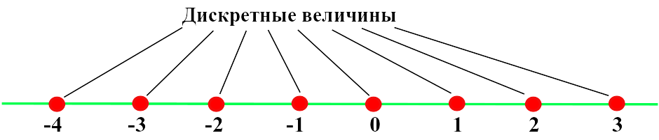
For example, consider a segment of a number line from -4 to 3 . As you can see, discrete quantities indicated by red dots - integers on it are only 8 pieces. The analog values shown by the green line in the figure are endless.
For example, we have a certain quantity X , which has a range of values from 0 to 127 . If we represent this quantity as analog , then theoretically we can represent it with any accuracy - for example, 12.123455454980 or 126.00000000007 or in general with a million decimal places.
But as soon as the microcontroller comes into play and the value of X acquires a discrete representation, then there can be no talk of any “infinite accuracy” even theoretically. Accuracy is limited by the number of binary digits, which we assign to the representation of the quantity X.
For example, we take 7 bits. In this case, we can represent the value of X with an accuracy of one. That is, you can specify X = 1 or X = 112 . But X = 112.5 cannot be indicated already - there is not enough bit depth. If we take for presentation of the same value of X not 7 , but 10 digits, then the accuracy of the representation will not be one, but 0.125 . And in this form, you can imagine X = 95.125 or X = 112.5 . But more precisely, for example, in the form X = 112.13 - this value cannot already be represented.
If you are confused by the fact that I write fractional values and at the same time I speak of them as integers, then remember that "discrete points" can be placed on a number line not in units, but for example in 0.5 or 0.125 units. But as they were, the final value will remain on any segment. And all the properties of a discrete quantity are preserved.
The key difference between a discrete value and an analog one is that on any finite segment of the number line there will be a finite number of discrete (integer) values and an infinite number of analog (real) values. Accordingly, we obtain that the discrete representation of quantities always has finite accuracy.
As a result of all the above, we get a trivial conclusion . Most of the measurable quantities of the real world are analog . Microcontrollers work only with discrete numerical representations of quantities. Therefore, before processing any analog value using a microcontroller, this value must be represented as a discrete one. Yes, and in binary form.
This conversion from analog to digital is called analog-to-digital conversion .
Analog to digital converter
A device for converting an analog signal to digital is called an ADC ( analog-to-digital converter ).
Typically, such a device has one or more analog inputs, to which an analog signal and a digital output are supplied with a given bit depth (usually from 8 to 16 bits).
Modern microcontrollers, including our ESP8266 , have built-in ADC units.
What are the characteristics of the ADC in general and the ESP8266 ADC in particular?
The first characteristic is what kind of input analog value the ADC converts into an output digital code. Most often, this value is the voltage at the analog input of the ADC. So it will be in our case. But in nature, there are ADCs with current input.
The second characteristic of the ADC, which is needed in practice, is the range of values of the input value of the ADC. In our case, this is the minimum and maximum voltage values at the input of the ADC. These values will be 0V and 1V, respectively. The input range of 1V seems small, but large voltages can always be divided and reduced, and small voltages can be amplified.
The third and perhaps the most important characteristic of the ADC is its capacity. This quantity determines the accuracy of the transformation or (by our analogy) - how often the "discrete" points are placed on the "real" number line. In our case, the ADC has a resolution of 10 . What does it mean? This means that the output digital code is represented by 10 binary digits and has 1024 values - from 0 to 1023.
Strictly speaking, it is worth remembering that the accuracy of the conversion depends not only on the bit depth, but also on a number of other parameters, for example, the linearity of the ADC. But much has already been written about this by very clever uncles in very clever books, so in this article I will leave the reader without details.
In addition, the ESP8266 ADC can detect overflow, that is, a situation where a voltage greater than 1V is applied to the input.
If you take a smart reference book on ADCs and look there, then there will be dozens of other characteristics. All of them are necessary and important, but we will not go so far. For example , we will not touch on the time parameters of the ADC , since we believe that in our case the measured values change rather slowly and the ADC converts them into a digital representation “instantly”.
To summarize the preliminary result .
The ShIoTiny controller has an ADC built into the ESP8266 .
A voltage in the range from 0 to 1V is applied to the input of the ADC ESP8266 .
At the output of the ESP8266 ADC, we get a number proportional to the input voltage in the range from 0 to 1023 . Voltage 0V corresponds to code 0 at the ADC output, voltage 1V corresponds to code 1023 at the ADC output.
Reading data from the ADC in ShIoTiny is performed at a speed of approximately 10 times per second .
The hardware input of the ADC is protected against overvoltage, similar to how the binary inputs Input1,2,3 are protected ( see here ).
That's it for the ShIoTiny ADC hardware .
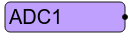
Now let's take a look at the ADC1 node, which processes data from the ESP8266 hardware ADC .
Software bells or whistles ADC1
In the program diagram in the ElDraw editor, the analog-to-digital converter assembly is called ADC1 .
As already mentioned, the ADC1 node receives data from the ESP8266 hardware ADC approximately 10 times per second . But the specified node does not calm down on this, but begins to process this data and even analyze it a little bit.
Firstly , it is checked - was there an ADC overflow? That is - but have the ADCs fed more than 1V to the input? If this situation is detected, then the output of the ADC1 node is set to NAN ( not a number ).
Secondly , if there was no overflow, the output value of the ADC 0..1023 is converted to the voltage value at the input of the ADC - a floating point number in the range 0..1 .
Thirdly , this converted value 0..1 is recalculated according to the formula where - voltage at the input of the ADC (from 0 to 1V ); k is the range ( ADC range ) and b is the offset ( ADC offset ). And finally, the obtained value of X is set to the output of the ADC1 node.
And finally in the fifth . If the value of X has changed by a specified percentage (from 1 to 100% ), then the ADC unit generates events, causing a conversion of the values of the nodes connected to it. This is essentially the “ ADC sensitivity ” parameter ( ADC changes, range% ). After all, there is usually no reason to react “to every sneeze”, that is, to scanty changes in the lower bits of the ADC - they often “make noise”. Therefore, the sensitivity parameter is of great practical importance.
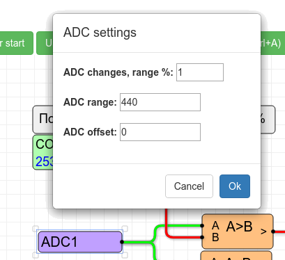
The legitimate question arises - how do we configure these settings? Click with your mouse on the ADC1 node in the diagram and you will immediately see the settings window.
In it, you can set everything you need. For our case, it will be such a window, as in the figure.
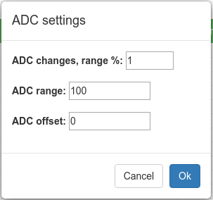
In this window, you can set all the parameters mentioned above - the range, offset and sensitivity of the ADC.
If you did not specify anything, then the range will be 1. The offset is zero. And the sensitivity is 1%.
That is, by default, in fact, the output of the ADC1 node will be the value of the analog voltage supplied to the ADC input.
As you can see, the ADC1 node is quite complex. Why is all this done? Yes for you, my dear users! I’m joking, of course, as a malicious egoist I took into account previous experience and tried to make my life easier.
We, as simple engineers, want the values to be presented not in "parrots", but in normal and understandable values - volts, amperes, kilograms or meters.
Many sensors give out the value precisely "in parrots", hoping that a smart microcontroller will recount them to the desired values.
For this purpose, the conversion of the measured ADC value by the function of the given one was introduced.
But, as usual, it is better to see once than to hear ten times. It’s also better to try once than to see ten times ... But that's not the point.
Therefore, I will give a couple of not complicated examples: a power supply control system and a temperature measuring system based on a sensor with a 4-20mA current output.
Mains monitoring
Measuring voltage is a common task. For example, we want to measure the voltage of the mains ~ 220V . If we have a bad electricity supply, the task is very real. We do not need a very, very accurate change. It is enough that when the voltage is exceeded by 15% of the norm, Relay1 is activated on the ShIoTiny , and when the voltage is reduced by 15% of the norm, the Relay2 relay is activated .
Of course, we cannot plug the ADC1 input of the ShIoTIny controller into a power outlet. What to do? Firstly, the voltage must be reduced to an acceptable level - 0..1V . And, secondly, it must be rectified: our ADC cannot measure the alternating voltage.
The voltage in the network can be both below the norm and above the norm. For simplicity, we assume that 220V of the mains voltage will correspond to 0.5V of the voltage at the ADC input.
Next, we look for any step-down transformer that, at ~ 220V of the input voltage, will give us, say ~ 3V of the output voltage, and assemble such a circuit as in the figure below.
Here a surprise can await the ignorant in electronics. At the output of the rectifier, not 3V DC voltage suddenly appears, but some 4V plus! In fact, everything is simply explained. When we measure an alternating voltage, the voltmeter shows us the actual voltage value. And when we rectify this voltage, then at the output of the rectifier we get the peak value of the voltage, which for a sinusoidal signal is about 1.41 , and exactly times more than the current one. Hence the "incomprehensible" 4.23V at the output of the rectifier.
And finally, we need to calculate the voltage divider, that is, the resistance R1 and R2 . We need to get a 0.5V divider at the output with a voltage of 4.23V at its input. So the rectified voltage of 4.23V should be divided by 8.46 times. To do this, set the resistor R2 = 100 Ohms , and the resistor R1 = 746 Ohms . But this is ideal. Actually, resistors with a resistance of 746 ohms do not exist. Yes, and transformers are not particularly accurate. Therefore, if anyone dares to try this solution, I strongly advise you to put the resistor R1 = 760 Ohms , and take the resistor R2 trimmer, with a resistance of 180 Ohms or 220 Ohms . Then you can, armed with a voltmeter, adjust R2 so that at ~ 220V the voltage at the primary winding of the transformer, at the output of the divider (or, which is the same, at the input of ADC1 ) is = 0.5V .
We measure voltage not just like that, but to do something by exceeding or decreasing it from the norm. For example, turn on the backup power so that some device does not burn out and does not turn off.
Therefore, we will draw the simplest program scheme, which, when the voltage is 15% above the norm, causes the relay Relay1 to work , and when the voltage decreases by 15% from the norm, the relay Relay2 works . In addition, overvoltage or undervoltage must be maintained on the network for at least 1 minute in order to trigger a relay. This will prevent false alarms during short voltage peaks that often occur on the network. The scheme program that implements our idea is shown in the figure.
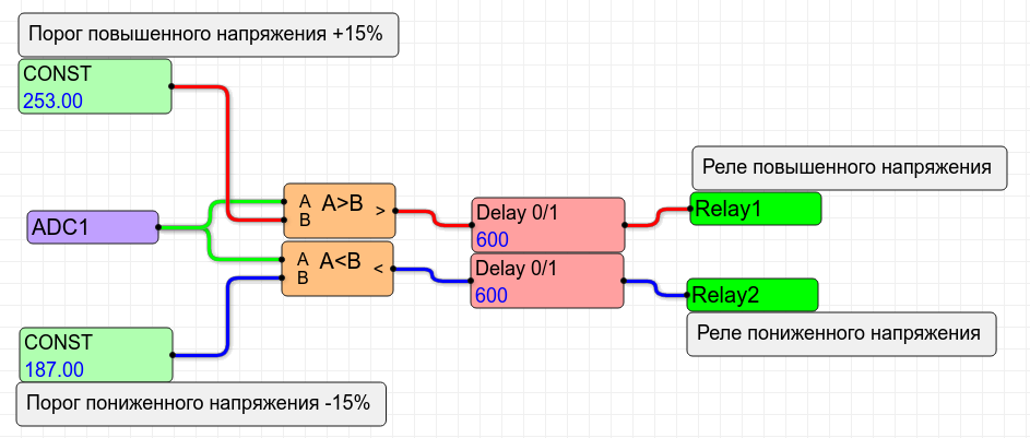
For this circuit to work, it is necessary to set the coefficient k (range) equal to 440 in the settings of the ADC parameters, as shown in the figure.
With a coefficient of 440 and a voltage voltage at the input of the ADC 0.5V, the output of the ADC1 node will be 220 . That is the real mains voltage!
This is very convenient, because it allows you to set the constants immediately in volts: 220V + 15% is 253V and 220V-15% is 187V . If necessary, these values can be easily changed without wasting time calculating and translating the voltage into “parrots”.
4-20mA temperature sensor
Sensors having a 4-20mA current output are very common in industry. In everyday life you will not meet them often. Nevertheless, someone has them and this someone wants to adapt them to the cause.
The ADC allows the use of such sensors in conjunction with the ShIoTiny controller.
Why is the sensor output current and precisely 4-20mA ? I will explain.
Current outputs work well on long lines. Say a kilometer. They do not care about the resistance of the wires: the current is the same along the entire length of the wire, regardless of the resistance of the conductors.
The initial current value of 4mA , and not just the lack of current, makes it easy to detect a wire break. If the sensor is whole and the wire is not broken, then there is always current. At least 4mA . And if the wire breaks, there is no current ( 0mA ).
Suppose we have a temperature sensor with a current output of 4-20mA and a range of measured temperature from -40C to + 125C . We want to connect it to ShIoTin . The first thing we need to do is convert the current to voltage. An ideal means for such a conversion is a conventional resistor.
Since the maximum voltage at the input of the ADC is 1V , and the maximum current in the line is 20mA , it is easy to calculate that a resistor that converts 20mA to 1V will have a resistance of 50 Ohms . ( Do not know Ohm's law - stay at home! ).
We will connect our sensor as shown in the figure.
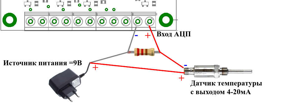
The sensor is a current generator proportional to the measured temperature. With a resistance of 50 Ohms connected in parallel with the ADC1 input, the following voltage values will be at the ADC input, depending on the current generated in the sensor circuit:
- current less than 4mA , voltage at the ADC input less than 0.2V - line break;
- current from 4mA to 20mA , voltage from 0.2V to 1V - the sensor is working;
- current is more than 20mA , input voltage is more than 1V - the sensor is faulty. With a short circuit in the sensor, a 50 ohm resistor may burn out if it is less than 2W power.
Suppose we want to measure temperature and publish it by MQTT . In addition, we will publish the status of the sensor (open circuit, short circuit or everything is in order).
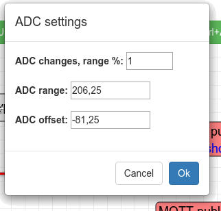
The first thing we need to do is to recalculate the value from the "parrots" to degrees. Knowing that a current of 4 mA and a voltage at the input of the ADC corresponds to a temperature of -40 ° C , 0.2 V , and a temperature of + 125 ° C corresponds to a current of 20 mA and a voltage at the input of an ADC of 1 V , we obtain the coefficients: k = 206.25 and b = -81.25 . Enter these coefficients in the ADC settings window, as shown in the figure.
Who wants to check the correctness of the calculation of k and b himself - decide for yourself the simplest system of equations:
Well, the program scheme will not be complicated at all and is shown in the figure below.

In the case when everything is fine and the 4-20mA temperature sensor is working , the temperature is published on the MQTT server under the name / t_sens . Signs of an accident are also published under the names / sens_short and / sens_break . If all is well, then the signs of an accident are zero.
If a line break occurs, the temperature will be less than -40C . In this case, the / sens_break parameter on the MQTT broker will be published as a unit.
If there is a short circuit in the line, then the temperature value will be more than + 125C . In this case, we will have a voltage greater than 1V at the input of the ADC and the ADC unit will set the output to NAN ( non-number ). In this case, the / sens_short parameter on the MQTT broker will be published as a unit.
If any of the alarms occurs , the Relay3 relay will trip , which can, for example, turn off the power to the sensor.
It turned out quite a “smart” sensor, which can be taken out, for example, 200 meters from the controller and measure the temperature.
Conclusion
Having finished the review of examples of ADCs on ShIoTiny, I realized that it can go on and on. But this will already be an article, but a textbook.
I apologize if for some the material seemed unnecessarily “childish” and detailed, but for some, on the contrary, something was not clear.
As usual - constructive criticism and suggestions are welcome. In addition, comments and suggestions are welcome.
You can send all this as usual in a comment or by mail: shiotiny@yandex.ru .
References
Since the article has a lot of third-party material that requires clarification, no links can be dispensed with.
How does the conversion of analog signal to digital
Analog and digital signal. Types of signals and how it works
List of voltage and electric current parameters
Analog field interfaces: 4-20 mA current loop - from simple to complex
SETTING ESPPOWER CLOUD MANAGEMENT THROUGH THE INTERNET WITH ANDROID
All Articles