Training Cisco 200-125 CCNA v3.0. Day 39. Stacks and aggregation of switch chassis
Today we look at the benefits of two types of switch aggregation: Switch Stacking, or switch stacks, and Chassis Aggregation, or aggregation of switch chassis. This is section 1.6 of the ICND2 exam topic.

When designing the company’s network, you will need to provide for the placement of Access Switches access switches, to which many user computers are connected, and Distribution Switches, distributor switches, to which these access switches are connected.
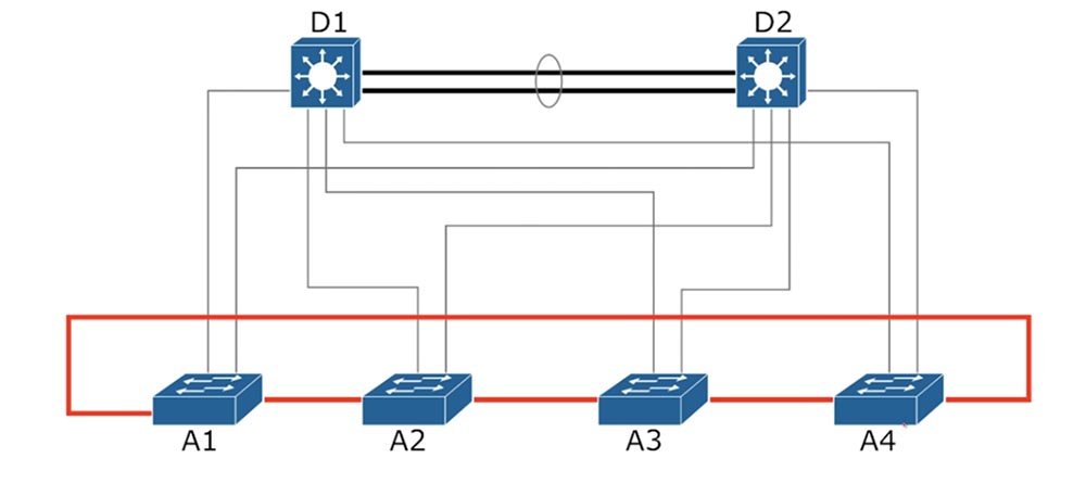
The diagram shows a Cisco model for OSI Level 3, where access switches are marked with the letter A and distribution switches with the letter D. You can have hundreds of devices on each floor of the company building, so you will need to choose between two ways to arrange the switches.

Each of the Access level switches has 24 ports, and if you need 100 ports, then there are approximately 5 such switches. Therefore, there are 2 ways: to increase the number of small switches or use one large switch with a hundred ports. The CCNA topic does not cover models of switches for 100 ports, but you can get such a switch, it is quite possible. So, you have to decide what suits you best - a few small ones or one big switch.
Each of the options has its own advantages. You can configure only 1 large switch instead of configuring a few small ones, but there is a drawback here - just one connection point to the network. If such a large switch fails, the entire network will collapse.
On the other hand, if you have five 24-port switches and one of them breaks, agree that the chance of failure of one switch is much greater than the chance of simultaneously breaking all five devices, so the other 4 switches will continue to provide the network . The disadvantage of this solution is the need to manage five different switches.
Our diagram shows 4 access switches connected to two distribution switches. According to OSI Layer 3 and Cisco network architecture requirements, each of these 4 switches must be connected to both distribution switches. When using the STP protocol, one of the 2 ports of each Access switch connected to the Distribution switch will be blocked. Technically, you cannot use the full bandwidth of the switch, because one of the two communication lines is always disconnected.
Usually all 4 switches are located on the same floor in a common rack - the photo shows 8 installed switches. There are a total of 192 ports in the rack. First of all, you must manually configure the IP addresses for each of these switches, and secondly, configure the VLAN everywhere, and this is a serious “headache” for the network administrator.

There is a thing that can make your task easier - Switch Stack. In our case, this thing will try to combine all 8 switches into one logical switch.

In this case, one of the switches will play the role of the Master switch, or the host of the stack. The network administrator can connect to this switch and make all the necessary settings that will automatically apply to all switches on the stack. After that, all 8 switches will work as one device.
Cisco uses various technologies to combine switches into stacks, in this case this external device is called “FlexStack module”. On the rear panel of the switch there is a port where this module is inserted.
FlexStack has two ports where the connecting cables are inserted: the lower port of the first switch in the rack connects to the upper port of the second, the lower port of the second to the upper port of the third and so on until the eighth switch, the lower port of which connects to the upper port of the first switch. In fact, we form a ring connection of switches of one stack.

In this case, one of the switches is selected by the master (Master), and the rest - slaves (Slave). After using FlexStack modules, all 4 switches of our circuit will act as 1 logical switch.
If the A1 master switch fails, all other stack switches will stop working. But if switch A3 breaks, the other three switches will continue to work as 1 logical switch.

In the original scheme, we had 6 physical devices, but after the organization of the Switch Stack, there were only 3: 2 physical and 1 logical switch. According to the first option, you would have to configure 6 different switches, which is already quite troublesome, so you can imagine how laborious the process of manually configuring hundreds of switches is. After combining the switches on the stack, we received one logical access switch, which is connected to each of the distribution switches D1 and D2 by four communication lines integrated into the EtherChannel. Since we have 3 devices, to prevent the formation of traffic loops, one EtherChannel will be blocked by STP.
So, the advantage of the switch stack is the ability to control one logical switch instead of several physical devices, which facilitates the network setup process.
There is another technology for combining switches called Chassis Aggregation. The difference between these technologies is that for the organization of Switch Stack you need a special external hardware module that is inserted into the switch.
In the second case, simply combining several devices on one common chassis, as a result of which you have the so-called aggregation switch chassis. In the photo you see the chassis for the Cisco 6500 series of switches. It combines 4 network cards with 24 ports, so this unit has 96 ports.

If necessary, you can add more interface modules - network cards, and all of them will be controlled by one module - the supervisor, which is the "brain" of the entire chassis. This chassis has two supervisor modules in case one of them fails, which creates some kind of redundancy, but it increases the reliability of the network. Typically, such expensive chassis are used at the system core level. This chassis has two power supplies, each of which can be powered from a different power source, which also increases the reliability of the network in the event of a power outage at one of the power substations.
Back to our original design, where there is also an EtherChannel between D1 and D2. Typically, when organizing such a connection, Ethernet ports are used. When using the chassis of switches, no external modules are needed; Ethernet ports are used directly to combine switches. You simply connect the first D1 interface module to the same D2 module, and the second D1 module to the second D2 module, and everything works together to form one Distribution Layer Switch.

If you look at the first version of the scheme, then for aggregation of 4 access switches and a distribution suite, you need to use the Multi-chassis EtherChannel program, which organizes EtherChannel channels for each access switch. You see that in this case there is a p2p - point-to-point connection, which excludes the formation of traffic loops, and in this case, all available communication lines are involved, and we do not have a decrease in bandwidth.
Typically, Chassis Aggregation is used for high-performance switches, and not for less powerful access switches. The architecture of Cisco allows the simultaneous use of both solutions - and Chassis Aggregation, and Switch Stack.

In this case, one common distribution logical switch and one common access logical switch are formed. In our scheme, 8 EtherChannel channels will be created that will work as one communication line, that is, as if we connected one distribution switch with one access switch with one cable. In this case, the “ports” of both devices will be in the forwarding state, and the network itself will work with maximum performance, using the bandwidth of all 8 channels.
Thank you for staying with us. Do you like our articles? Want to see more interesting materials? Support us by placing an order or recommending it to your friends, a 30% discount for Habr users on a unique analogue of entry-level servers that was invented by us for you: The whole truth about VPS (KVM) E5-2650 v4 (6 Cores) 10GB DDR4 240GB SSD 1Gbps from $ 20 or how to divide the server? (options are available with RAID1 and RAID10, up to 24 cores and up to 40GB DDR4).
Dell R730xd 2 times cheaper? Only we have 2 x Intel TetraDeca-Core Xeon 2x E5-2697v3 2.6GHz 14C 64GB DDR4 4x960GB SSD 1Gbps 100 TV from $ 199 in the Netherlands! Dell R420 - 2x E5-2430 2.2Ghz 6C 128GB DDR3 2x960GB SSD 1Gbps 100TB - from $ 99! Read about How to Build Infrastructure Bldg. class c using Dell R730xd E5-2650 v4 servers costing 9,000 euros for a penny?
When designing the company’s network, you will need to provide for the placement of Access Switches access switches, to which many user computers are connected, and Distribution Switches, distributor switches, to which these access switches are connected.
The diagram shows a Cisco model for OSI Level 3, where access switches are marked with the letter A and distribution switches with the letter D. You can have hundreds of devices on each floor of the company building, so you will need to choose between two ways to arrange the switches.
Each of the Access level switches has 24 ports, and if you need 100 ports, then there are approximately 5 such switches. Therefore, there are 2 ways: to increase the number of small switches or use one large switch with a hundred ports. The CCNA topic does not cover models of switches for 100 ports, but you can get such a switch, it is quite possible. So, you have to decide what suits you best - a few small ones or one big switch.
Each of the options has its own advantages. You can configure only 1 large switch instead of configuring a few small ones, but there is a drawback here - just one connection point to the network. If such a large switch fails, the entire network will collapse.
On the other hand, if you have five 24-port switches and one of them breaks, agree that the chance of failure of one switch is much greater than the chance of simultaneously breaking all five devices, so the other 4 switches will continue to provide the network . The disadvantage of this solution is the need to manage five different switches.
Our diagram shows 4 access switches connected to two distribution switches. According to OSI Layer 3 and Cisco network architecture requirements, each of these 4 switches must be connected to both distribution switches. When using the STP protocol, one of the 2 ports of each Access switch connected to the Distribution switch will be blocked. Technically, you cannot use the full bandwidth of the switch, because one of the two communication lines is always disconnected.
Usually all 4 switches are located on the same floor in a common rack - the photo shows 8 installed switches. There are a total of 192 ports in the rack. First of all, you must manually configure the IP addresses for each of these switches, and secondly, configure the VLAN everywhere, and this is a serious “headache” for the network administrator.
There is a thing that can make your task easier - Switch Stack. In our case, this thing will try to combine all 8 switches into one logical switch.
In this case, one of the switches will play the role of the Master switch, or the host of the stack. The network administrator can connect to this switch and make all the necessary settings that will automatically apply to all switches on the stack. After that, all 8 switches will work as one device.
Cisco uses various technologies to combine switches into stacks, in this case this external device is called “FlexStack module”. On the rear panel of the switch there is a port where this module is inserted.
FlexStack has two ports where the connecting cables are inserted: the lower port of the first switch in the rack connects to the upper port of the second, the lower port of the second to the upper port of the third and so on until the eighth switch, the lower port of which connects to the upper port of the first switch. In fact, we form a ring connection of switches of one stack.
In this case, one of the switches is selected by the master (Master), and the rest - slaves (Slave). After using FlexStack modules, all 4 switches of our circuit will act as 1 logical switch.
If the A1 master switch fails, all other stack switches will stop working. But if switch A3 breaks, the other three switches will continue to work as 1 logical switch.
In the original scheme, we had 6 physical devices, but after the organization of the Switch Stack, there were only 3: 2 physical and 1 logical switch. According to the first option, you would have to configure 6 different switches, which is already quite troublesome, so you can imagine how laborious the process of manually configuring hundreds of switches is. After combining the switches on the stack, we received one logical access switch, which is connected to each of the distribution switches D1 and D2 by four communication lines integrated into the EtherChannel. Since we have 3 devices, to prevent the formation of traffic loops, one EtherChannel will be blocked by STP.
So, the advantage of the switch stack is the ability to control one logical switch instead of several physical devices, which facilitates the network setup process.
There is another technology for combining switches called Chassis Aggregation. The difference between these technologies is that for the organization of Switch Stack you need a special external hardware module that is inserted into the switch.
In the second case, simply combining several devices on one common chassis, as a result of which you have the so-called aggregation switch chassis. In the photo you see the chassis for the Cisco 6500 series of switches. It combines 4 network cards with 24 ports, so this unit has 96 ports.
If necessary, you can add more interface modules - network cards, and all of them will be controlled by one module - the supervisor, which is the "brain" of the entire chassis. This chassis has two supervisor modules in case one of them fails, which creates some kind of redundancy, but it increases the reliability of the network. Typically, such expensive chassis are used at the system core level. This chassis has two power supplies, each of which can be powered from a different power source, which also increases the reliability of the network in the event of a power outage at one of the power substations.
Back to our original design, where there is also an EtherChannel between D1 and D2. Typically, when organizing such a connection, Ethernet ports are used. When using the chassis of switches, no external modules are needed; Ethernet ports are used directly to combine switches. You simply connect the first D1 interface module to the same D2 module, and the second D1 module to the second D2 module, and everything works together to form one Distribution Layer Switch.
If you look at the first version of the scheme, then for aggregation of 4 access switches and a distribution suite, you need to use the Multi-chassis EtherChannel program, which organizes EtherChannel channels for each access switch. You see that in this case there is a p2p - point-to-point connection, which excludes the formation of traffic loops, and in this case, all available communication lines are involved, and we do not have a decrease in bandwidth.
Typically, Chassis Aggregation is used for high-performance switches, and not for less powerful access switches. The architecture of Cisco allows the simultaneous use of both solutions - and Chassis Aggregation, and Switch Stack.
In this case, one common distribution logical switch and one common access logical switch are formed. In our scheme, 8 EtherChannel channels will be created that will work as one communication line, that is, as if we connected one distribution switch with one access switch with one cable. In this case, the “ports” of both devices will be in the forwarding state, and the network itself will work with maximum performance, using the bandwidth of all 8 channels.
Thank you for staying with us. Do you like our articles? Want to see more interesting materials? Support us by placing an order or recommending it to your friends, a 30% discount for Habr users on a unique analogue of entry-level servers that was invented by us for you: The whole truth about VPS (KVM) E5-2650 v4 (6 Cores) 10GB DDR4 240GB SSD 1Gbps from $ 20 or how to divide the server? (options are available with RAID1 and RAID10, up to 24 cores and up to 40GB DDR4).
Dell R730xd 2 times cheaper? Only we have 2 x Intel TetraDeca-Core Xeon 2x E5-2697v3 2.6GHz 14C 64GB DDR4 4x960GB SSD 1Gbps 100 TV from $ 199 in the Netherlands! Dell R420 - 2x E5-2430 2.2Ghz 6C 128GB DDR3 2x960GB SSD 1Gbps 100TB - from $ 99! Read about How to Build Infrastructure Bldg. class c using Dell R730xd E5-2650 v4 servers costing 9,000 euros for a penny?
All Articles