Training Cisco 200-125 CCNA v3.0. Day 38. EtherChannel Protocol for OSI Layer 2
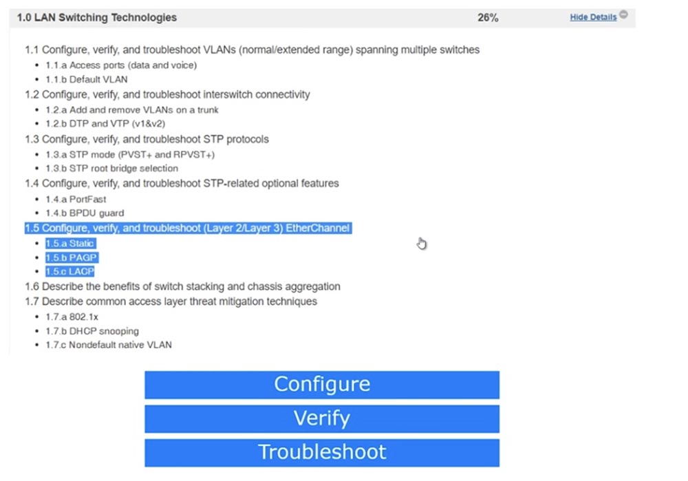
Today we look at the operation of the Layer 2 EtherChannel link aggregation protocol for layer 2 of the OSI model. This protocol is not too different from the Layer 3 protocol, but before I start learning about the Layer 3 EtherChannel, I need to introduce you to several concepts, so we'll move on to the third layer later. We continue to follow the CCNA course schedule, so today we’ll look at section 1.5 “Configuring, Verifying, and Troubleshooting Layer 2/3 EtherChannel” and subsections 1.5a “Static EtherChannel”, 1.5b “PAGP Protocol” and 1.5c “Open IEEE-LACP Standard” .
Before moving on, we need to understand what an EtherChannel is. Suppose we have switch A and switch B, excessively connected by three communication lines. If you use the STP protocol, two extra lines will be logically blocked to prevent the formation of loops.
Suppose we have FastEthernet ports that provide 100 Mbps traffic speed, so the total throughput is 3 x 100 = 300 Mbps. We leave only one communication channel, because of which it will drop to 100 Mbps, that is, in this case STP will degrade the network performance. In addition, 2 extra channels will be idle in vain.
To prevent this, KALPANA, the developer of Cisco Catalist switches and later acquired by Cisco, developed a technology called EtherChannel in the 1990s.
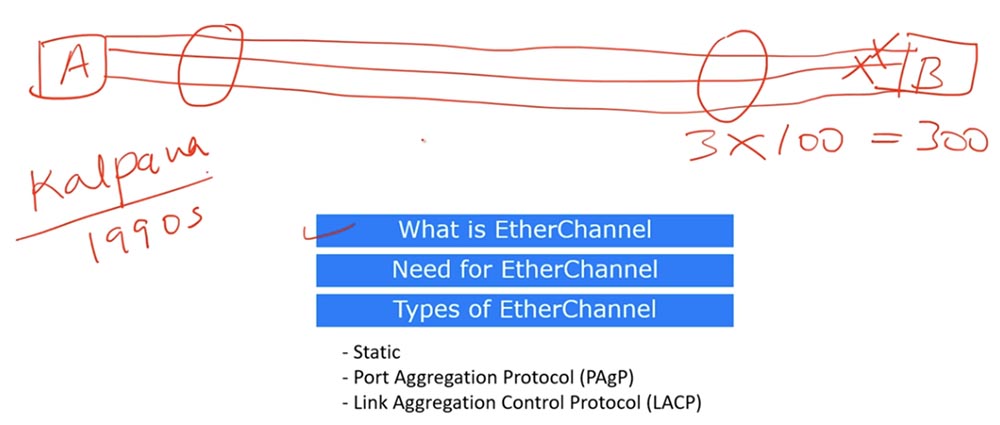
In our case, this technology turns three separate communication channels into one logical channel with a throughput of 300 Mbps.
The first mode of EtherChannel technology is manual or static mode. At the same time, the switches will not do anything under any transmission conditions, relying on the fact that all manual settings for the operation parameters are made correctly. The channel simply turns on and works, completely trusting the settings of the network administrator.
The second mode is the Cisco PAGP proprietary link aggregation protocol; the third is the IEEE standard LACP link aggregation protocol.
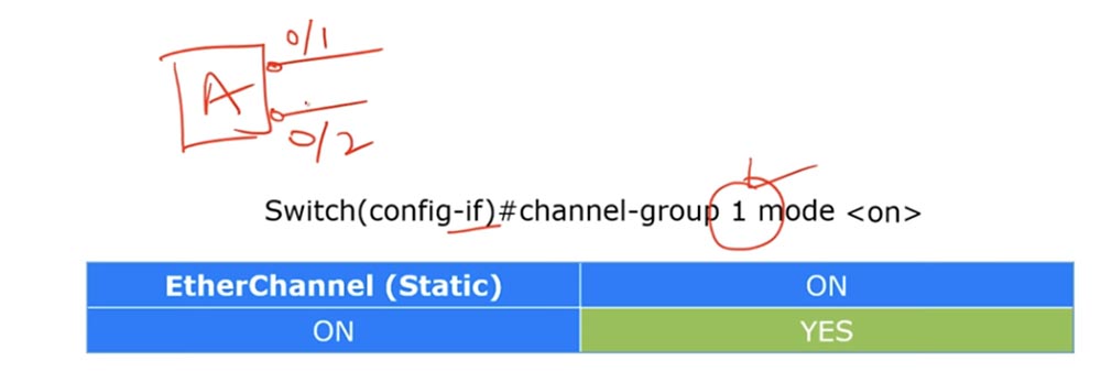
In order for these modes to work, the EtherChannel must be made available. The static version of this protocol is very easy to activate: you need to go into the switch interface settings and enter the channel-group 1 mode command.
If we have switch A with two interfaces f0 / 1 and f0 / 2, we must go into the settings of each port and enter this command, and the EtherChannel interface group number can be from 1 to 6, the main thing is that this value is the same for all ports of the switch. In addition, ports must operate in the same modes: both in access mode or both in trunk mode and have the same native VLAN or allowed VLANs.
EtherChannel aggregation will only work if the channel group consists of the same configured interfaces.
We connect switch A with two communication lines to switch B, which also has two interfaces f0 / 1 and f0 / 2. These interfaces form their own group. You can configure them to work in EtherChannel using the same command, and the group number does not matter, since they are located on the local switch. You can designate this group as number 1, and everything will work. However, remember that for both channels to work without problems, all interfaces must be configured exactly the same, for the same mode - access or trunk. After you go into the settings of both interfaces of switch A and switch B and enter the command channel-group 1 mode on, the aggregation of EtherChannel channels will be performed.
Both physical interfaces of each switch will work as one logical interface. If we look at the STP parameters, we will see that switch A will show one common interface, grouped from two physical ports.
Let's move on to PAGP, a port aggregation protocol developed by Cisco.

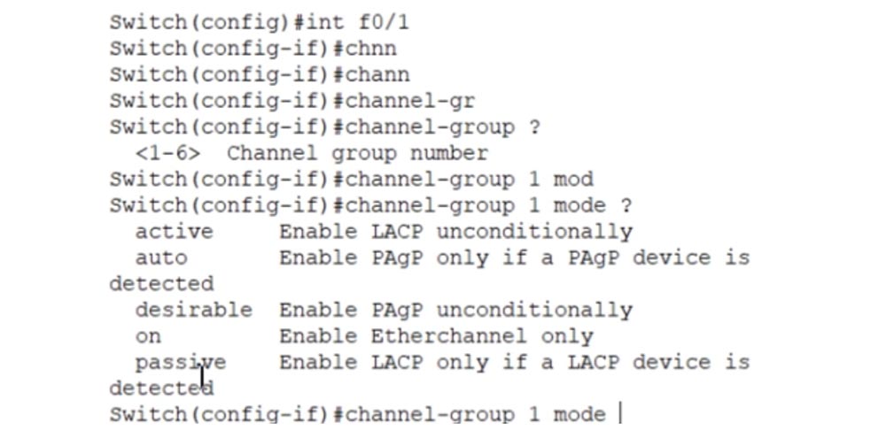
Imagine the same picture - two switches A and B, each with interfaces f0 / 1 and f0 / 2, connected by two communication lines. To enable PAGP, use the same channel-group 1 mode command with the <desirable / auto> parameters. In manual static mode, you simply enter the channel-group 1 mode on command on all interfaces, and the aggregation starts working, here you need to specify the desirable or auto parameter. If you enter the channel-group 1 mode command with the? Sign, the system will display a hint with the following options: on, desirable, auto, passive, active.
If you enter the same channel-group 1 mode desirable command at both ends of the link, EtherChannel will be activated. The same will happen if at one end of the channel the interfaces are configured with the channel-group 1 mode auto command, and at the other end with the channel-group 1 mode auto command.
However, if the interfaces at both ends of the channels are set to auto with the channel-group 1 mode auto command, channel aggregation will not occur. Therefore, remember - if you want to use EtherChannel via PAGP, the interfaces of at least one of the parties must be in desirable state.
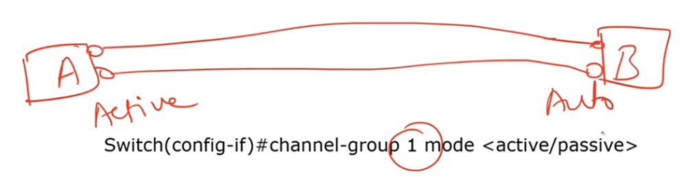
When using the open LACP protocol, the same channel-group 1 mode command with the <active / passive> parameters is used for channel aggregation.

Possible combinations of settings on both sides of the channels are as follows: if the interfaces are set to active mode or one side is active and the other side is passive - EtherChannel mode will work, if both groups of interfaces are set to passive, channel aggregation will not occur. It must be remembered that in order to organize channel aggregation using the LACP protocol, it is necessary that at least one of the interface groups be in the active state.
Let's try to answer the question: if we have switches A and B connected by communication lines, with the interfaces of one switch in the active state and the other in the auto or desirable state, will EtherChannel work?
No, it won’t, because the network must have the same protocol — either PAGP or LACP, since they are not compatible with each other.
Consider a few commands used to organize an EtherChannel. First of all, you need to assign a group number, it can be any. For the first channel-group 1 mode command, you can select 5 parameters as an option: on, desirable, auto, passive or active.
In the interface subcommands, we use the channel-group keyword, but if, for example, you want to specify load balancing, the word port-channel is used. Consider what load balancing is.
Suppose we have switch A with two ports that are connected to the corresponding ports of switch B. Three computers are connected to switch B - 1,2,3, and one computer, number 4, to switch A.
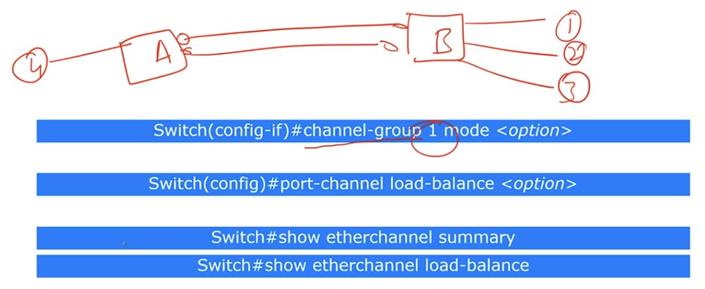
When traffic moves from computer # 4 to computer # 1, switch A will begin to transmit packets on both communication lines. The load balancing method uses hashing of the sender's MAC address so that all traffic on the fourth computer will go through only one of the two communication lines. If we connect computer No. 5 to switch A, due to load balancing, the traffic of this computer will only move along one, lower communication line.
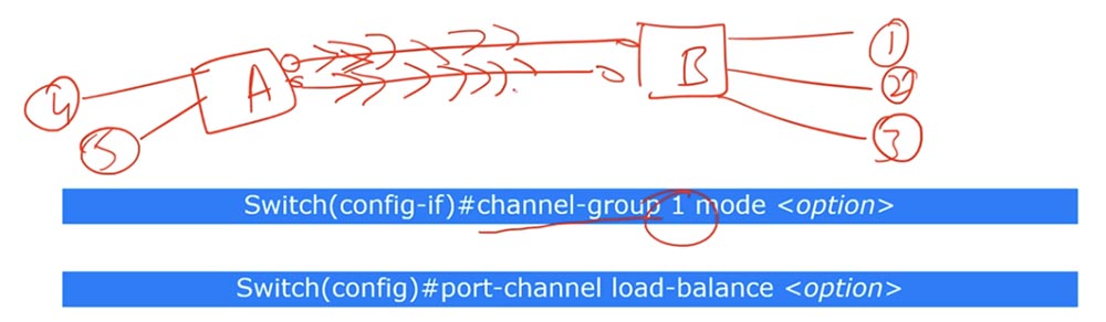
However, this is not a typical situation. Let's say we have a cloud Internet and a device to which switch A is connected with three computers. Internet traffic will be directed to the switch with the MAC address of this device, that is, with the address of a specific port, because this device is a gateway. Thus, all outgoing traffic will have the MAC address of this device.

If we place switch B connected to it by three communication lines before switch A, then all traffic of switch B in the direction of switch A will rush along one of the lines, which does not meet our goals. Therefore, we need to set the balancing parameters for this switch.

To do this, use the port-channel load-balance command, where the destination IP address is used as the option parameter. If this is the address of computer No. 1, traffic will rush along the first line, if No. 3 - along the third, and if you specify the IP address of the second computer, then on the middle line.

To do this, the command uses the port-channel keyword in global configuration mode.
If you want to see which links are involved in the channel and which protocols are used, then in privileged mode you need to enter the show etherchannel summary command. You can view the load balancing settings using the show etherchannel load-balance command.
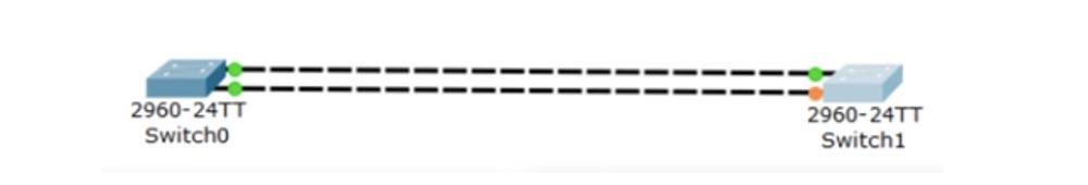
Now consider all this in the Packet Tracer program. We have 2 switches connected by two links. STP will begin its work, and one of the 4 ports will be blocked.
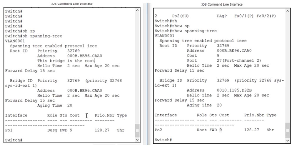
We go into the settings of SW0 and enter the show spanning-tree command. We see that STP is working and can check the Root ID and Bridge ID. Using the same command for the second switch, we will see that the first switch SW0 is the root switch, since it, unlike SW1, has the same Root and Bridge identifiers. In addition, there is a message that SW0 is the root - “This bridge is the root”.
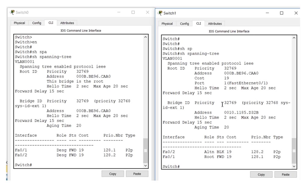
Both ports of the root switch are in Designated state, the blocked port of the second switch is indicated as Alternative, and the second as the root port. You see how STP flawlessly performs all the necessary work, automatically setting up the connection.
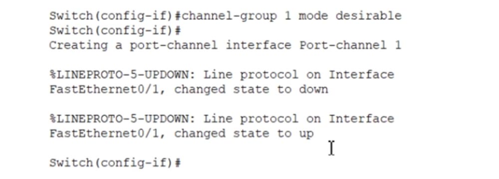
We activate the PAGP protocol, for this, in the settings of SW0, we will sequentially enter the commands int f0 / 1 and channel-group 1 mode with one of 5 possible parameters, I use desirable.
You see that the linear protocol was first turned off and then turned back on, that is, the changes made took effect and the Port-channel 1 interface was created.
Now let's move on to the f0 / 2 interface and enter the same command channel-group 1 mode desirable.
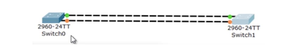
You see that now the ports of the upper link are marked with a green marker, and the ports of the lower one are marked with orange. In this case, there cannot be a mixed mode of ports desirable - auto, because all interfaces of the same switch must be configured with the same command. Auto mode can be used on the second switch, but on the first all ports should work in the same mode, in this case it is desirable.
We will go into the settings of SW1 and use the command for the range of interfaces int range f0 / 1-2, so as not to manually enter the commands separately for each of the interfaces, but to configure both with one command.
I use the channel-group 2 mode command, but I can use any number from 1 to 6 to denote the group of interfaces of the second switch. Since the opposite side of the channel is set to desirable mode, the interfaces of this switch must be in desirable or auto mode. I select the first parameter, type channel-group 2 mode desirable and press Enter.
We see a message that the channel interface Port-channel 2 was created, and the ports f0 / 1 and f0 / 2 sequentially switched from the down state to the up state. This is followed by a message that the Port-channel 2 interface has turned up and that the line protocol of this interface has also been enabled. Now we have the EtherChannel aggregated channel.
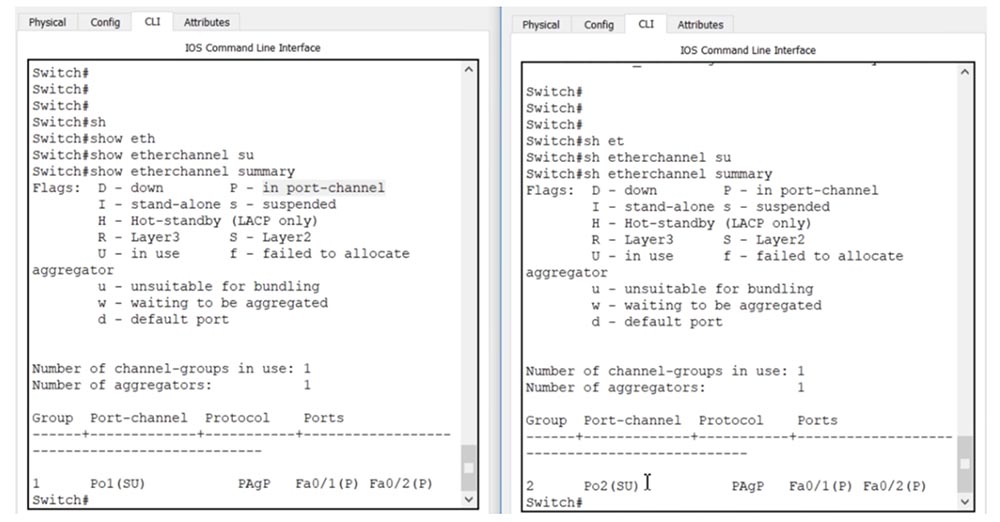
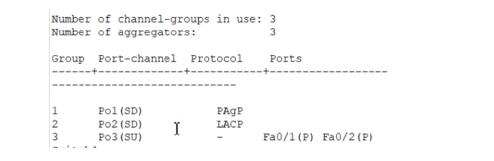
You can verify this by going to switch settings SW0 and issuing the show etherchannel summary command. You see various flags, which we will consider later, and then group 1 using 1 channel, the number of aggregators is also 1. Po1 means PortChannel 1, and the designation (SU) stands for S - flag of level 2, U - used. The following is the PAGP protocol used and the physical ports aggregated into the channel are Fa0 / 1 (P) and Fa0 / 2 (P), where the P flag indicates that these ports are part of the PortChannel.
I use the same commands for the second switch, and similar information for SW1 appears in the CLI window.
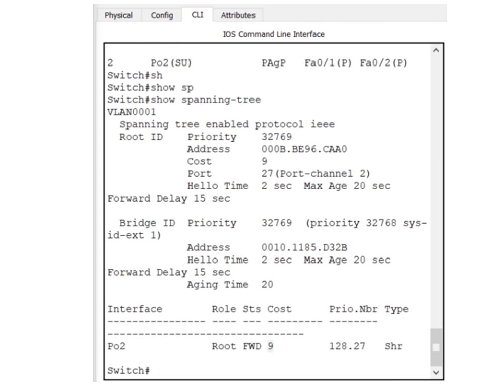
I enter the show spanning-tree command in the SW1 settings, and you can see that PortChannel 2 represents one logical interface, and its cost has decreased compared to the cost of two separate ports 19 and is now equal to 9.
Let's do the same with the first switch. You see that the Root parameters have not changed, but now between the two switches instead of two physical links there is one logical interface Po1-Po2.
Let's try replacing PAGP with LACP. To do this, in the settings of the first switch, I use the command for the range of interfaces int range f0 / 1-2. If I now enter the channel-group1 mode active command to enable LACP, it will be rejected because the ports Fa0 / 1 and Fa0 / 2 are already part of a channel using a different protocol.

Therefore, I must first enter the command no channel-group 1 mode active and only then use the command channel-group1 mode active. Let's do the same with the second switch by first entering the no channel-group 2 command and then the channel-group 2 mode active command. If you look at the interface parameters, you can see that Po2 turned on again, but it is still in the PAGP protocol mode. This is not true, because we now have LACP, and in this case there is an incorrect display of parameters by the Packet Tracer program.
To resolve this discrepancy, I am using a temporary solution - creating another PortChannel. To do this, I type the commands int range f0 / 1-2 and no channel-group 2, and then the command channel-group 2 mode active. Let's see how this affects the first switch. I enter the show etherchannel summary command and see that Po1 is again shown as using PAGP. This is a Packet Tracer simulation problem, because PortChannel is currently disabled and we don’t have to have a channel at all.
I go back to the CLI window of the second switch and issue the show etherchannel summary command. Now Po2 is shown with an index (SD), where D means down, that is, the channel does not work. Technically, PortChannel is present, but not used, because no port is associated with it.
I enter int range f0 / 1-2 and no channel-group 1 commands in the settings of the first switch, and then create a new channel group, this time under number 2, using the channel-group 2 mode active command. Then I do the same in the settings of the second switch, only now the channel group gets the number 1.
Now a new Port Channel 2 group has been created on the first switch, and Port Channel 1 on the second switch. I just swapped the names of the groups. As you can see, technically I created a new Port Channel on the second switch, and now it displays with the correct parameter - after entering the show etherchannel summary command, we see that Po1 (SU) uses LACP.
We see exactly the same picture in the CLI window of the SW0 switch - the new Po2 (SU) group is running LACP.

Consider the difference between an interface in the active state and an interface that is always on. I will create a new channel group for switch SW0 with the commands int range f0 / 1-2 and channel-group 3 mode on. Before that, it is necessary to delete channel groups 1 and 2 with the no channel-group 1 and no channel-group 2 commands, otherwise when you try to use the channel-group 3 mode on command, the system will display a message that the interface is already used to work with another channel protocol.
Do the same with the second switch - delete channel-group 1 and 2 and create group 3 with the command channel-group 3 mode on. Now let's go into the settings of SW0 and use the show etherchannel summary command. You will see that the new Po3 channel is already operational and does not require any preliminary operations, like PAGP or LACP.
It turns on immediately, without disconnecting and then turning on the ports. Using the same command for SW1, we will see that here Po3 does not use any protocol, that is, we have created a static EtherChannel.
Cisco claims that for widespread network availability, you need to forget about PAGP and use the static EtherChannel as a more reliable way of link aggregation.
How do we balance load? I return to the SWI switch CLI window and issue the show etherchannel load-balance command. You see that load balancing is done based on the MAC address of the source MAC address.
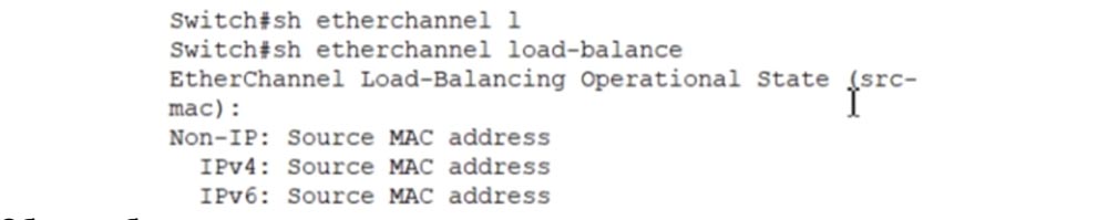
Usually balancing uses this particular parameter, but sometimes it does not correspond to our tasks. If we want to change this balancing method, we need to enter the global configuration mode and enter the port-channel load-balance command, after which the system will give prompts with possible parameters for this command.
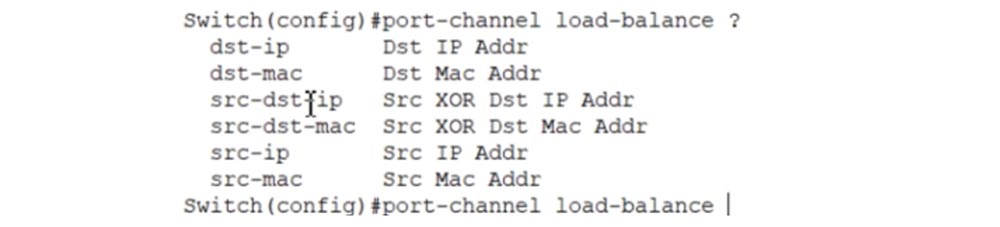
If you specify the port-channel load-balance src-mac parameter, that is, specify the source MAC address, a hash function will be enabled, which will then indicate which port, which is part of this EtherChannel, should be used to transmit traffic. Each time the source address is the same, the system will use this particular physical interface to send traffic.
Thank you for staying with us. Do you like our articles? Want to see more interesting materials? Support us by placing an order or recommending it to your friends, a 30% discount for Habr users on a unique analogue of entry-level servers that was invented by us for you: The whole truth about VPS (KVM) E5-2650 v4 (6 Cores) 10GB DDR4 240GB SSD 1Gbps from $ 20 or how to divide the server? (options are available with RAID1 and RAID10, up to 24 cores and up to 40GB DDR4).
Dell R730xd 2 times cheaper? Only we have 2 x Intel TetraDeca-Core Xeon 2x E5-2697v3 2.6GHz 14C 64GB DDR4 4x960GB SSD 1Gbps 100 TV from $ 199 in the Netherlands! Dell R420 - 2x E5-2430 2.2Ghz 6C 128GB DDR3 2x960GB SSD 1Gbps 100TB - from $ 99! Read about How to Build Infrastructure Bldg. class c using Dell R730xd E5-2650 v4 servers costing 9,000 euros for a penny?
Before moving on, we need to understand what an EtherChannel is. Suppose we have switch A and switch B, excessively connected by three communication lines. If you use the STP protocol, two extra lines will be logically blocked to prevent the formation of loops.
Suppose we have FastEthernet ports that provide 100 Mbps traffic speed, so the total throughput is 3 x 100 = 300 Mbps. We leave only one communication channel, because of which it will drop to 100 Mbps, that is, in this case STP will degrade the network performance. In addition, 2 extra channels will be idle in vain.
To prevent this, KALPANA, the developer of Cisco Catalist switches and later acquired by Cisco, developed a technology called EtherChannel in the 1990s.
In our case, this technology turns three separate communication channels into one logical channel with a throughput of 300 Mbps.
The first mode of EtherChannel technology is manual or static mode. At the same time, the switches will not do anything under any transmission conditions, relying on the fact that all manual settings for the operation parameters are made correctly. The channel simply turns on and works, completely trusting the settings of the network administrator.
The second mode is the Cisco PAGP proprietary link aggregation protocol; the third is the IEEE standard LACP link aggregation protocol.
In order for these modes to work, the EtherChannel must be made available. The static version of this protocol is very easy to activate: you need to go into the switch interface settings and enter the channel-group 1 mode command.
If we have switch A with two interfaces f0 / 1 and f0 / 2, we must go into the settings of each port and enter this command, and the EtherChannel interface group number can be from 1 to 6, the main thing is that this value is the same for all ports of the switch. In addition, ports must operate in the same modes: both in access mode or both in trunk mode and have the same native VLAN or allowed VLANs.
EtherChannel aggregation will only work if the channel group consists of the same configured interfaces.
We connect switch A with two communication lines to switch B, which also has two interfaces f0 / 1 and f0 / 2. These interfaces form their own group. You can configure them to work in EtherChannel using the same command, and the group number does not matter, since they are located on the local switch. You can designate this group as number 1, and everything will work. However, remember that for both channels to work without problems, all interfaces must be configured exactly the same, for the same mode - access or trunk. After you go into the settings of both interfaces of switch A and switch B and enter the command channel-group 1 mode on, the aggregation of EtherChannel channels will be performed.
Both physical interfaces of each switch will work as one logical interface. If we look at the STP parameters, we will see that switch A will show one common interface, grouped from two physical ports.
Let's move on to PAGP, a port aggregation protocol developed by Cisco.
Imagine the same picture - two switches A and B, each with interfaces f0 / 1 and f0 / 2, connected by two communication lines. To enable PAGP, use the same channel-group 1 mode command with the <desirable / auto> parameters. In manual static mode, you simply enter the channel-group 1 mode on command on all interfaces, and the aggregation starts working, here you need to specify the desirable or auto parameter. If you enter the channel-group 1 mode command with the? Sign, the system will display a hint with the following options: on, desirable, auto, passive, active.
If you enter the same channel-group 1 mode desirable command at both ends of the link, EtherChannel will be activated. The same will happen if at one end of the channel the interfaces are configured with the channel-group 1 mode auto command, and at the other end with the channel-group 1 mode auto command.
However, if the interfaces at both ends of the channels are set to auto with the channel-group 1 mode auto command, channel aggregation will not occur. Therefore, remember - if you want to use EtherChannel via PAGP, the interfaces of at least one of the parties must be in desirable state.
When using the open LACP protocol, the same channel-group 1 mode command with the <active / passive> parameters is used for channel aggregation.
Possible combinations of settings on both sides of the channels are as follows: if the interfaces are set to active mode or one side is active and the other side is passive - EtherChannel mode will work, if both groups of interfaces are set to passive, channel aggregation will not occur. It must be remembered that in order to organize channel aggregation using the LACP protocol, it is necessary that at least one of the interface groups be in the active state.
Let's try to answer the question: if we have switches A and B connected by communication lines, with the interfaces of one switch in the active state and the other in the auto or desirable state, will EtherChannel work?
No, it won’t, because the network must have the same protocol — either PAGP or LACP, since they are not compatible with each other.
Consider a few commands used to organize an EtherChannel. First of all, you need to assign a group number, it can be any. For the first channel-group 1 mode command, you can select 5 parameters as an option: on, desirable, auto, passive or active.
In the interface subcommands, we use the channel-group keyword, but if, for example, you want to specify load balancing, the word port-channel is used. Consider what load balancing is.
Suppose we have switch A with two ports that are connected to the corresponding ports of switch B. Three computers are connected to switch B - 1,2,3, and one computer, number 4, to switch A.
When traffic moves from computer # 4 to computer # 1, switch A will begin to transmit packets on both communication lines. The load balancing method uses hashing of the sender's MAC address so that all traffic on the fourth computer will go through only one of the two communication lines. If we connect computer No. 5 to switch A, due to load balancing, the traffic of this computer will only move along one, lower communication line.
However, this is not a typical situation. Let's say we have a cloud Internet and a device to which switch A is connected with three computers. Internet traffic will be directed to the switch with the MAC address of this device, that is, with the address of a specific port, because this device is a gateway. Thus, all outgoing traffic will have the MAC address of this device.
If we place switch B connected to it by three communication lines before switch A, then all traffic of switch B in the direction of switch A will rush along one of the lines, which does not meet our goals. Therefore, we need to set the balancing parameters for this switch.
To do this, use the port-channel load-balance command, where the destination IP address is used as the option parameter. If this is the address of computer No. 1, traffic will rush along the first line, if No. 3 - along the third, and if you specify the IP address of the second computer, then on the middle line.
To do this, the command uses the port-channel keyword in global configuration mode.
If you want to see which links are involved in the channel and which protocols are used, then in privileged mode you need to enter the show etherchannel summary command. You can view the load balancing settings using the show etherchannel load-balance command.
Now consider all this in the Packet Tracer program. We have 2 switches connected by two links. STP will begin its work, and one of the 4 ports will be blocked.
We go into the settings of SW0 and enter the show spanning-tree command. We see that STP is working and can check the Root ID and Bridge ID. Using the same command for the second switch, we will see that the first switch SW0 is the root switch, since it, unlike SW1, has the same Root and Bridge identifiers. In addition, there is a message that SW0 is the root - “This bridge is the root”.
Both ports of the root switch are in Designated state, the blocked port of the second switch is indicated as Alternative, and the second as the root port. You see how STP flawlessly performs all the necessary work, automatically setting up the connection.
We activate the PAGP protocol, for this, in the settings of SW0, we will sequentially enter the commands int f0 / 1 and channel-group 1 mode with one of 5 possible parameters, I use desirable.
You see that the linear protocol was first turned off and then turned back on, that is, the changes made took effect and the Port-channel 1 interface was created.
Now let's move on to the f0 / 2 interface and enter the same command channel-group 1 mode desirable.
You see that now the ports of the upper link are marked with a green marker, and the ports of the lower one are marked with orange. In this case, there cannot be a mixed mode of ports desirable - auto, because all interfaces of the same switch must be configured with the same command. Auto mode can be used on the second switch, but on the first all ports should work in the same mode, in this case it is desirable.
We will go into the settings of SW1 and use the command for the range of interfaces int range f0 / 1-2, so as not to manually enter the commands separately for each of the interfaces, but to configure both with one command.
I use the channel-group 2 mode command, but I can use any number from 1 to 6 to denote the group of interfaces of the second switch. Since the opposite side of the channel is set to desirable mode, the interfaces of this switch must be in desirable or auto mode. I select the first parameter, type channel-group 2 mode desirable and press Enter.
We see a message that the channel interface Port-channel 2 was created, and the ports f0 / 1 and f0 / 2 sequentially switched from the down state to the up state. This is followed by a message that the Port-channel 2 interface has turned up and that the line protocol of this interface has also been enabled. Now we have the EtherChannel aggregated channel.
You can verify this by going to switch settings SW0 and issuing the show etherchannel summary command. You see various flags, which we will consider later, and then group 1 using 1 channel, the number of aggregators is also 1. Po1 means PortChannel 1, and the designation (SU) stands for S - flag of level 2, U - used. The following is the PAGP protocol used and the physical ports aggregated into the channel are Fa0 / 1 (P) and Fa0 / 2 (P), where the P flag indicates that these ports are part of the PortChannel.
I use the same commands for the second switch, and similar information for SW1 appears in the CLI window.
I enter the show spanning-tree command in the SW1 settings, and you can see that PortChannel 2 represents one logical interface, and its cost has decreased compared to the cost of two separate ports 19 and is now equal to 9.
Let's do the same with the first switch. You see that the Root parameters have not changed, but now between the two switches instead of two physical links there is one logical interface Po1-Po2.
Let's try replacing PAGP with LACP. To do this, in the settings of the first switch, I use the command for the range of interfaces int range f0 / 1-2. If I now enter the channel-group1 mode active command to enable LACP, it will be rejected because the ports Fa0 / 1 and Fa0 / 2 are already part of a channel using a different protocol.
Therefore, I must first enter the command no channel-group 1 mode active and only then use the command channel-group1 mode active. Let's do the same with the second switch by first entering the no channel-group 2 command and then the channel-group 2 mode active command. If you look at the interface parameters, you can see that Po2 turned on again, but it is still in the PAGP protocol mode. This is not true, because we now have LACP, and in this case there is an incorrect display of parameters by the Packet Tracer program.
To resolve this discrepancy, I am using a temporary solution - creating another PortChannel. To do this, I type the commands int range f0 / 1-2 and no channel-group 2, and then the command channel-group 2 mode active. Let's see how this affects the first switch. I enter the show etherchannel summary command and see that Po1 is again shown as using PAGP. This is a Packet Tracer simulation problem, because PortChannel is currently disabled and we don’t have to have a channel at all.
I go back to the CLI window of the second switch and issue the show etherchannel summary command. Now Po2 is shown with an index (SD), where D means down, that is, the channel does not work. Technically, PortChannel is present, but not used, because no port is associated with it.
I enter int range f0 / 1-2 and no channel-group 1 commands in the settings of the first switch, and then create a new channel group, this time under number 2, using the channel-group 2 mode active command. Then I do the same in the settings of the second switch, only now the channel group gets the number 1.
Now a new Port Channel 2 group has been created on the first switch, and Port Channel 1 on the second switch. I just swapped the names of the groups. As you can see, technically I created a new Port Channel on the second switch, and now it displays with the correct parameter - after entering the show etherchannel summary command, we see that Po1 (SU) uses LACP.
We see exactly the same picture in the CLI window of the SW0 switch - the new Po2 (SU) group is running LACP.
Consider the difference between an interface in the active state and an interface that is always on. I will create a new channel group for switch SW0 with the commands int range f0 / 1-2 and channel-group 3 mode on. Before that, it is necessary to delete channel groups 1 and 2 with the no channel-group 1 and no channel-group 2 commands, otherwise when you try to use the channel-group 3 mode on command, the system will display a message that the interface is already used to work with another channel protocol.
Do the same with the second switch - delete channel-group 1 and 2 and create group 3 with the command channel-group 3 mode on. Now let's go into the settings of SW0 and use the show etherchannel summary command. You will see that the new Po3 channel is already operational and does not require any preliminary operations, like PAGP or LACP.
It turns on immediately, without disconnecting and then turning on the ports. Using the same command for SW1, we will see that here Po3 does not use any protocol, that is, we have created a static EtherChannel.
Cisco claims that for widespread network availability, you need to forget about PAGP and use the static EtherChannel as a more reliable way of link aggregation.
How do we balance load? I return to the SWI switch CLI window and issue the show etherchannel load-balance command. You see that load balancing is done based on the MAC address of the source MAC address.
Usually balancing uses this particular parameter, but sometimes it does not correspond to our tasks. If we want to change this balancing method, we need to enter the global configuration mode and enter the port-channel load-balance command, after which the system will give prompts with possible parameters for this command.
If you specify the port-channel load-balance src-mac parameter, that is, specify the source MAC address, a hash function will be enabled, which will then indicate which port, which is part of this EtherChannel, should be used to transmit traffic. Each time the source address is the same, the system will use this particular physical interface to send traffic.
Thank you for staying with us. Do you like our articles? Want to see more interesting materials? Support us by placing an order or recommending it to your friends, a 30% discount for Habr users on a unique analogue of entry-level servers that was invented by us for you: The whole truth about VPS (KVM) E5-2650 v4 (6 Cores) 10GB DDR4 240GB SSD 1Gbps from $ 20 or how to divide the server? (options are available with RAID1 and RAID10, up to 24 cores and up to 40GB DDR4).
Dell R730xd 2 times cheaper? Only we have 2 x Intel TetraDeca-Core Xeon 2x E5-2697v3 2.6GHz 14C 64GB DDR4 4x960GB SSD 1Gbps 100 TV from $ 199 in the Netherlands! Dell R420 - 2x E5-2430 2.2Ghz 6C 128GB DDR3 2x960GB SSD 1Gbps 100TB - from $ 99! Read about How to Build Infrastructure Bldg. class c using Dell R730xd E5-2650 v4 servers costing 9,000 euros for a penny?
All Articles