Training Cisco 200-125 CCNA v3.0. Day 37. STP: Root Bridge selection, PortFast and BPDU guard features. Part 1
Before starting the lesson, I want to say that our site now has a My Points system. Earned points can be spent on paying for orders in our online store. Points can be earned by participating in our CCNA tests, visiting the site, attracting new users, etc.
Today we will continue to study topics according to the Cisco schedule and consider the following issues: 1.3b “STP Root Switch Selection”, 1.4 “Configuring, Verifying, and Problems with Additional STP Features”, 1.4a “PortFast” and 1.4b “BPDU guard”.
Regardless of the type or version of the STP protocol, 3 mandatory steps are taken during its implementation: choosing the root switch, determining the best route to the root switch and blocking all other routes.
The choice of the root switch (according to the old terminology - the root bridge) is carried out according to priority, and if you do not know what it is, you should watch the previous video tutorial in which I talked about this. After one of the switches is selected as Root Bridge, all other switches will try to find the optimal route to it based on the minimum cost, I also spoke about this in the previous video. If two routes have the same cost, you need to pay attention to Bridge ID, I will discuss this later. The third step is to block all other paths to prevent traffic loops. Consider these three steps in action.
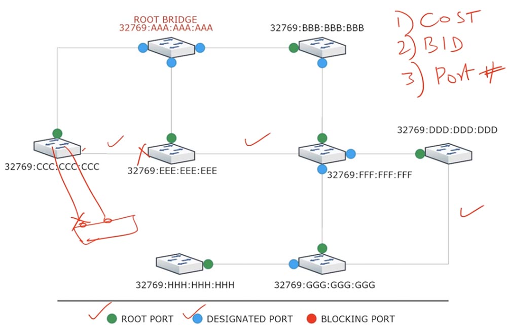
You see a typical network of 8 switches on the screen, where I have already prioritized all the switches, for convenience they have the same values 32769, and the MAC addresses of each switch.
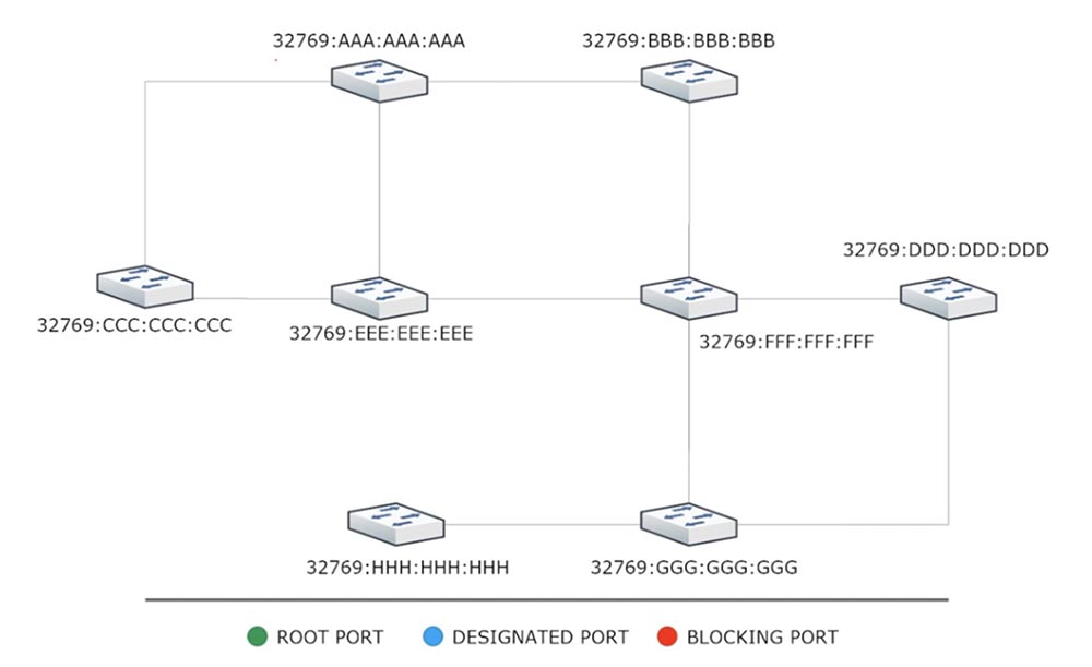
As soon as these switches are plugged into the network, the first thing they will do is to share BPDU messages with each other. Switch A will send a message on three ports to which switches C, E and B are connected. Upon receiving this message, switch C will think: “Switch A has the best Bridge ID, because although we have the same priorities, A is better than C”, and will consider switch A root. In the case of MAC addresses, the switch always wins the switch for which the address is less, in the STP world this means "better."
Next, the switch C will send an update to the switch E, which will say: “the root switch is the switch A, and my Bridge ID is 32769: CCC: CCC: CCC”. When switch E receives this BPDU frame, it will say: “Yes, indeed, A is better than my E”, update this BPDU with its Bridge ID and send it further over the network. Thus, after some time, all the other 7 switches will agree that A is the root switch.
The next step is that all these switches start looking for the shortest path to the root switch. Suppose all these devices are connected using FastEthernet and the cost of each port is 19. When the Root Bridge sends out BPDUs, it says: “I am the root switch, and the cost of the route to me is 0”, that is, it sends zero cost attached to the switches route.
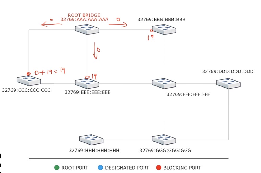
Upon receiving this message to a port with a value of 19, switch C concludes that the cost of the route to the root switch for it will be 0 + 19 = 19. Switches E and B arrive in the same way, receiving the same cost of ports - 19.
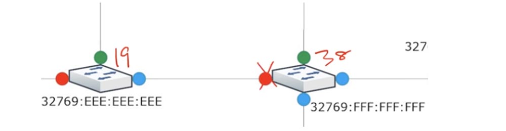
Next, the switch C tells the switch E that for it the cost of the route to the root switch is 19. Switch E, having received this BPDU on the port connecting it to the switch C, determines the cost as the sum of 19 + 19 and receives the cost of the route to the Root Bridge on this port equal to 38. Switch E also sends BPDU to switch C, which, having received this frame, determines the cost of the port from E also equal to 38.
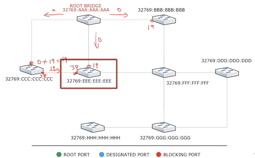
Next, switch E chooses the lowest cost of its two ports, sees that cost 19 is better than cost 38, and sends the BPDU frame to switch F, saying that its value is 19. Switch F adds this cost to the cost of its port and receives the cost of both ports - facing E and facing B - equal to 19 + 19 = 38.
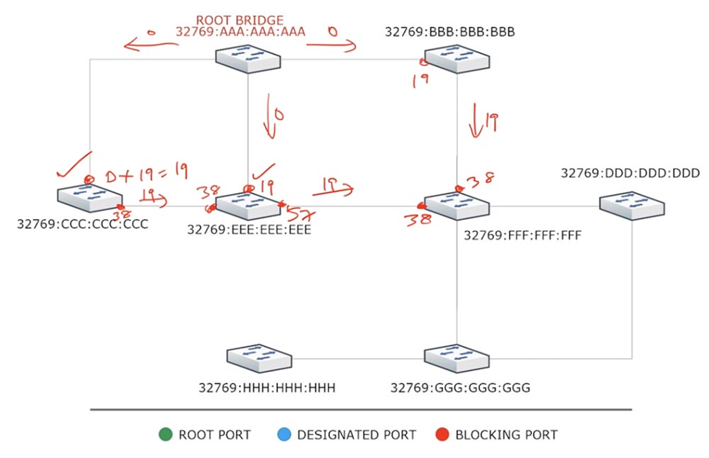
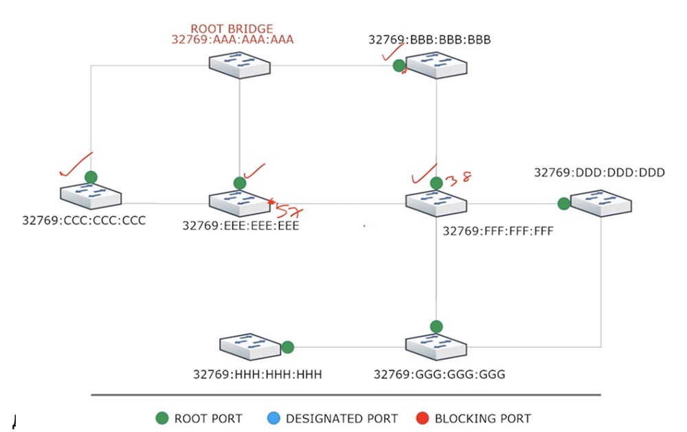
Gradually, all switches will calculate the cost of the route to the root switch for all their ports and select their Root Port. For example, switch A, comparing the costs of the two involved ports 19 and 38, selects the cost 19 and designates this port as the root port of the Root Port.
Switch E will compare the three ports involved with costs 38, 19, and 57 and select the top port with a value of 19 as the root port. Switch F compares the cost of the two ports 38 and 38 and sees that they are equal. In this case, he will begin to compare the MAC addresses of switches E and B, select the best one, that is, B, and designate the root port of the switch to this switch.
A port connected directly to the root switch usually becomes the root port. There may be nuances, because in any case, a cost estimate is made, and if the choice is between Fast Ethernet and Gigabit Ethernet ports, the root port will be selected based on the minimum cost. I already talked about this in the previous video, so I won’t repeat it.
The remaining devices of our network will also calculate the cost of the route and select their Root Port, in the diagram they are indicated by a green marker.
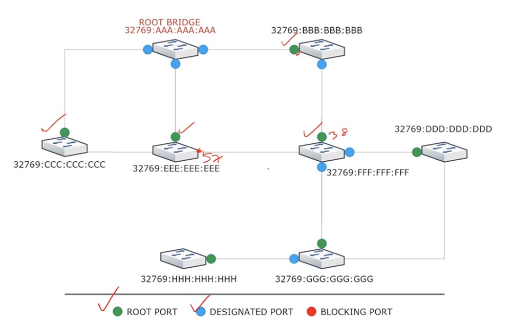
Next, select the designated Designated Port. Any of the switch ports can become a designated port, that is, a port through which backup communication with the root switch will be carried out. Assume that the channel connecting switch C to root switch A is damaged. In this case, switch C will lose communication with the root switch, as it will lose the only port connecting them. In the root switch, all ports — assigned, are in the Forwarding state and cannot stay in the Blocking state, and for the rest of the switches, the port responsible for the connection of this switch with its network segment becomes the designated one.
Each network segment can have only one Designated Port, and any part of the network that has a root port must have a designated port. These ports are always in the Forwarding state, and just like the root ports, they cannot be in the Blocking state.
So, first you select Root Port, and then Designated Port - the latter in the diagram are indicated in blue. We have three network segments: these are CE, FE and DG, where there are ports whose role is not indicated. Please note that it is in these network sections that loops can occur, so they need to be logically disconnected. To do this, at one end of the segment must be a Blocking Port.
Consider the first network segment: which of the switches should have a blocked port - switch C or switch B?
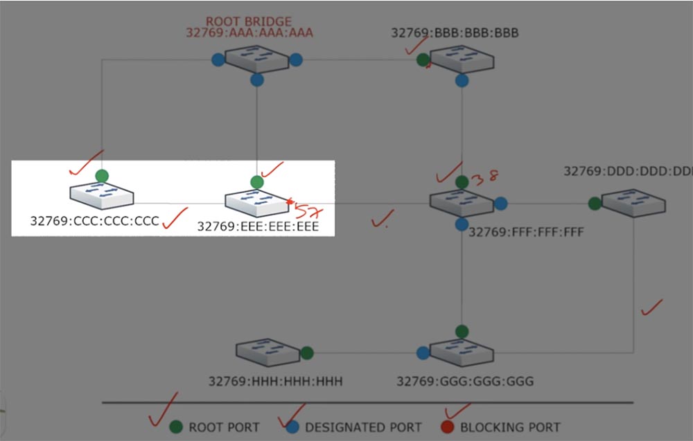
To do this, we must again return to the cost and see which of these switches has a lower route cost to the root switch. Since they both have the same cost, we move on to BID comparison. Switch C has a smaller, that is, a better BID than E, that is, its MAC address is less than the MAC address of switch E. Therefore, the port of the “best” switch C is selected as Designated Port, and the port of switch E becomes Blocking Port. At the same time, it does not matter at all that a blocked port is located opposite the designated port, the main thing is that in this case we do not form a loop.
If we imagine that we have another device connected to the switch, and both devices have the same port cost and the same Bridge ID, then in this case the port numbers become the criterion for comparison. The port with the lower number becomes the Designated Port, and the port with the higher number becomes the Blocking Port.
So, there are 3 criteria for choosing a designated port: port cost, BID, and port number.
On the second section of the network, the Blocking Port is selected simply: the cost is 38 more than 19, so the port with a lower cost becomes assigned, and the opposite port is blocked.
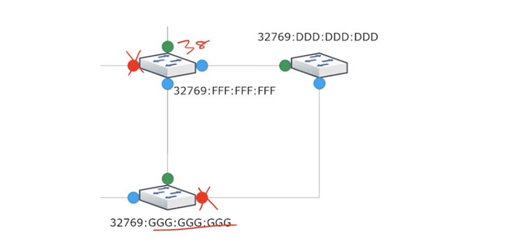
In the third section, the ports of switches D and G have the same cost 38 + 19 = 57, but since the MAC address of switch D is “better” than address G, its port becomes assigned, and the port of switch G connected to D becomes Blocking Port.
I remind you again: physically, the Blocking Port does not turn off and continues to receive BPDUs, it just blocks any traffic to prevent loops. The blocked port itself does not send BPDUs, but continues to receive and calculate them.
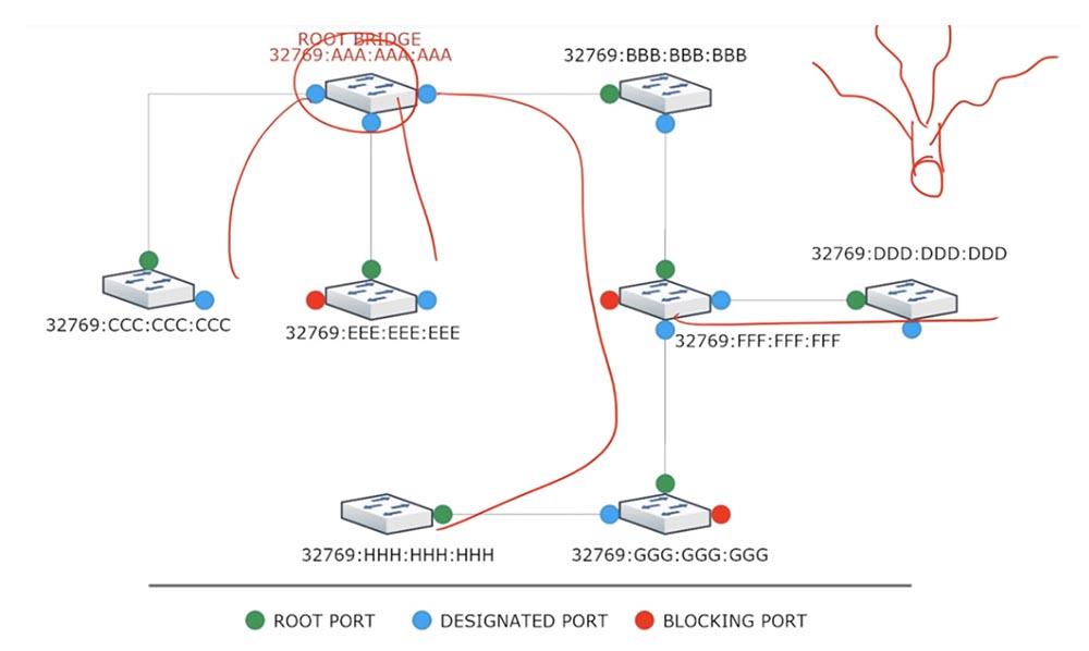
This is how the Root Bridge is selected when implementing the STP process. This scheme can be simplified by imagining that there are no blocked ports at all, then it will be clearly visible that with this topology there are no traffic loops. The name "covering tree" comes from the fact that we have a kind of root - a switch, from which branches branch out - communication channels with other devices. If you look at the Root Bridge as the root of a tree, you will see how branches to other switches move away from it. This is the easiest way to remember what STP is.
Next, we will consider the needs for providing RSTP. I already talked about this accelerated version and explained what the difference between STP and RSTP is. If any port is blocked, the usual STP expects 10 hello timers, which is 10x2 s = 20 s, and for another 15 s it goes to Listening and Learning modes, that is, it takes 50 seconds before the port enters the Forwarding state.
Most new devices boot in 5-10 seconds. Suppose you came to the office, turned on your computer and cannot log in to the network, because the switch to which it is connected has still not moved from the Blocking state to the Forwarding state. This is a problem because you may not understand what the true cause of the problem is.
To fix this problem, they came up with a temporary easy-to-implement solution called PortFast. This is a feature of the STP protocol that allows the Edged Port port with an end user connected to immediately transition to the Forwarding state, bypassing the Listening and Learning states.
The last port is the port to which a device that does not send BPDUs is connected. That is, if you have a network of 3 switches, then we are talking about those ports to which neighboring switches are not connected. Typically, a computer or server is connected to the Edged Port. Since these ports do not accept BPDUs or should not be technically accepted, they can be turned into something called PortFast. This is a Cisco development, and to enable this feature on the switch port you need to use the simple spanning-tree portfast command. In fact, this command disables STP on this port, which after blocking immediately enters the forwarding state, bypassing the transition states.
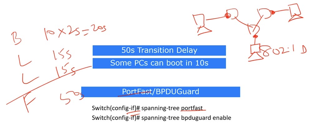
The problem is that if you connect a switch to such a port instead of a computer, this could potentially create a loop. To solve this problem, they came up with another technology called BPDUGuard. To enable this function, go to the interface settings and enter the spanning-tree bpduguard enable command. The meaning of BPDUGuard is to prevent the port from receiving BPDUs. Technically, upon receiving such a frame, the interface immediately enters the error-disabled state, that is, it is disabled.
It will remain in this state until the network administrator fixes the cause of the problem, for example, disconnects a switch that is mistakenly connected to PortFast. Thus, using PortFast makes it faster, and using BPDUGuard prevents the receipt of BPDU messages and the associated formation of traffic loops. As I said, these are temporary solutions aimed at reducing the transmission time of traffic.
Next, you see a table that shows the differences between STP and RSTP.
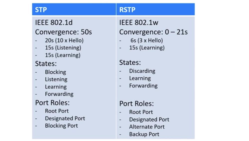
These protocols use different IEEE standards, RSTP has a shorter convergence time - up to 21 seconds versus 50 seconds for STP. If the network consists of switches supporting only RSTP, the convergence time will be 0 s.
If the RSTP switch is connected to the STP switch, it can accept BPDUs due to backward compatibility, but the STP will not understand the BPDUs sent to it by the RSTP. In this case, the convergence time will increase to 21 s - the sum of the triple period of the hello timer and the duration of the Listening listening.
The BPDUs of the STP and RSTP protocols are very similar in structure, but a detailed discussion of the differences between these frames is part of the CCNA course. It is important that in the RSTP protocol, when the full-duplex (point / point) connection is activated, the Proposal / Agreement mechanism is used, which serves to quickly switch to the Forwarding state.
Suppose we have two RSTP switches connected to each other. The first switch sends the second BPDU and then blocks its port. The second switch receives this frame and compares its information with its table - does it contain information about the best cost and the best route to the root switch. If such information is available, the second switch responds with the first Proposal message asking it to open the “best” port for it, while blocking its other ports. After receiving the Proposal of the second switch, the first sends him the consent of the Agreement, after which the connection between the two switches is immediately established.
Thus, the convergence time in this case will be 0 seconds, in contrast to the STP switches with a convergence rate of 50 seconds.
The STP switch has 4 states, and RST - only 3, this is due to the fact that the RSTP Discarding state corresponds to the first two STP states: Blocking and Listening. The remaining states are the same for both protocols.
STP ports can play three roles: the root Root port, the Designated destination port, and the blocked Blocking port. RSTP also has the first two ports, and the blocked port can be of two types: Alternate (alternative) and Backup (backup).
Suppose that in STP we have 3 devices: switch A and a hub, to which another switch B is connected. Since they are connected through the hub, we have a common network segment. Both switches have RP root ports. By priority, switch A has a Designated Port, and switch B has a Blocking Port.

If RSTP is used instead of STP in this scheme, we will need to choose whether the blocked port plays the role of an alternative port or a backup port. If we choose the role of Alternate, then this port will be able to accept BPDUs from another bridge, or switch, that is, in the event of a root root switch failure, alternative port B will assume its responsibilities.
Suppose switch B is connected by two lines to another hub. Since we had a second hub, we also got a second network segment, which should also have its own Blocking Port. As I said, in the case of STP, a comparison will be made by cost, BID and port number, after which the “smaller” port will become Designated, and the larger one will be Blocking. I will designate the second blocked port of the switch In cross.
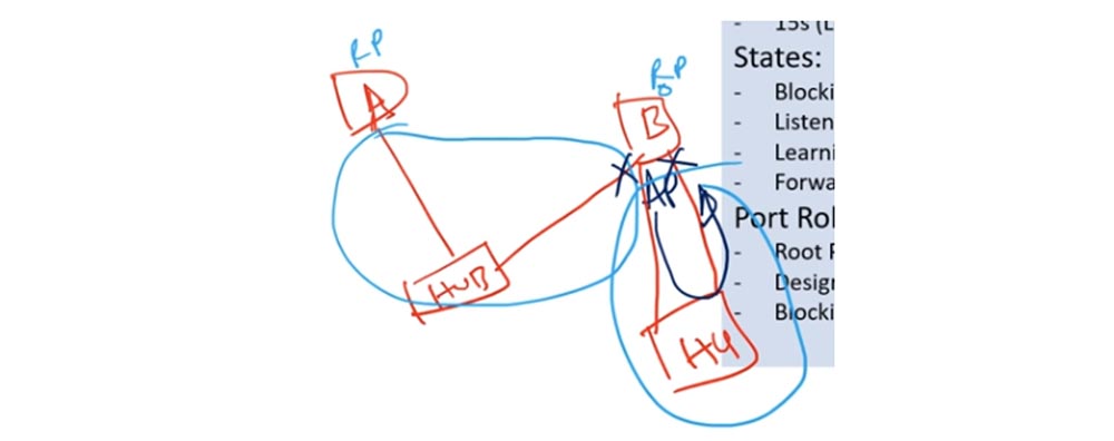
This port cannot be an alternative, because the BPDU it receives will be sent to itself on another Blocking Port. Having looked at this frame, the switch will say: “I received this BPDU from myself, which means that it came from the same common network segment. I will make this port standby because it can only accept BPDUs that are directed by me. " Thus, RSTP divides ports into alternative ports, capable of receiving BPDUs from other switches, and reserve ones, capable of receiving their own BPDUs.
This is not the case in STP, because the port will play the role of Blocking in both cases. I hope you understand the difference between Alternate and Backup ports.
33:20 min
Thank you for staying with us. Do you like our articles? Want to see more interesting materials? Support us by placing an order or recommending it to your friends, a 30% discount for Habr users on a unique analogue of entry-level servers that was invented by us for you: The whole truth about VPS (KVM) E5-2650 v4 (6 Cores) 10GB DDR4 240GB SSD 1Gbps from $ 20 or how to divide the server? (options are available with RAID1 and RAID10, up to 24 cores and up to 40GB DDR4).
Dell R730xd 2 times cheaper? Only we have 2 x Intel TetraDeca-Core Xeon 2x E5-2697v3 2.6GHz 14C 64GB DDR4 4x960GB SSD 1Gbps 100 TV from $ 199 in the Netherlands! Dell R420 - 2x E5-2430 2.2Ghz 6C 128GB DDR3 2x960GB SSD 1Gbps 100TB - from $ 99! Read about How to Build Infrastructure Bldg. class c using Dell R730xd E5-2650 v4 servers costing 9,000 euros for a penny?
Today we will continue to study topics according to the Cisco schedule and consider the following issues: 1.3b “STP Root Switch Selection”, 1.4 “Configuring, Verifying, and Problems with Additional STP Features”, 1.4a “PortFast” and 1.4b “BPDU guard”.
Regardless of the type or version of the STP protocol, 3 mandatory steps are taken during its implementation: choosing the root switch, determining the best route to the root switch and blocking all other routes.
The choice of the root switch (according to the old terminology - the root bridge) is carried out according to priority, and if you do not know what it is, you should watch the previous video tutorial in which I talked about this. After one of the switches is selected as Root Bridge, all other switches will try to find the optimal route to it based on the minimum cost, I also spoke about this in the previous video. If two routes have the same cost, you need to pay attention to Bridge ID, I will discuss this later. The third step is to block all other paths to prevent traffic loops. Consider these three steps in action.
You see a typical network of 8 switches on the screen, where I have already prioritized all the switches, for convenience they have the same values 32769, and the MAC addresses of each switch.
As soon as these switches are plugged into the network, the first thing they will do is to share BPDU messages with each other. Switch A will send a message on three ports to which switches C, E and B are connected. Upon receiving this message, switch C will think: “Switch A has the best Bridge ID, because although we have the same priorities, A is better than C”, and will consider switch A root. In the case of MAC addresses, the switch always wins the switch for which the address is less, in the STP world this means "better."
Next, the switch C will send an update to the switch E, which will say: “the root switch is the switch A, and my Bridge ID is 32769: CCC: CCC: CCC”. When switch E receives this BPDU frame, it will say: “Yes, indeed, A is better than my E”, update this BPDU with its Bridge ID and send it further over the network. Thus, after some time, all the other 7 switches will agree that A is the root switch.
The next step is that all these switches start looking for the shortest path to the root switch. Suppose all these devices are connected using FastEthernet and the cost of each port is 19. When the Root Bridge sends out BPDUs, it says: “I am the root switch, and the cost of the route to me is 0”, that is, it sends zero cost attached to the switches route.
Upon receiving this message to a port with a value of 19, switch C concludes that the cost of the route to the root switch for it will be 0 + 19 = 19. Switches E and B arrive in the same way, receiving the same cost of ports - 19.
Next, the switch C tells the switch E that for it the cost of the route to the root switch is 19. Switch E, having received this BPDU on the port connecting it to the switch C, determines the cost as the sum of 19 + 19 and receives the cost of the route to the Root Bridge on this port equal to 38. Switch E also sends BPDU to switch C, which, having received this frame, determines the cost of the port from E also equal to 38.
Next, switch E chooses the lowest cost of its two ports, sees that cost 19 is better than cost 38, and sends the BPDU frame to switch F, saying that its value is 19. Switch F adds this cost to the cost of its port and receives the cost of both ports - facing E and facing B - equal to 19 + 19 = 38.
Gradually, all switches will calculate the cost of the route to the root switch for all their ports and select their Root Port. For example, switch A, comparing the costs of the two involved ports 19 and 38, selects the cost 19 and designates this port as the root port of the Root Port.
Switch E will compare the three ports involved with costs 38, 19, and 57 and select the top port with a value of 19 as the root port. Switch F compares the cost of the two ports 38 and 38 and sees that they are equal. In this case, he will begin to compare the MAC addresses of switches E and B, select the best one, that is, B, and designate the root port of the switch to this switch.
A port connected directly to the root switch usually becomes the root port. There may be nuances, because in any case, a cost estimate is made, and if the choice is between Fast Ethernet and Gigabit Ethernet ports, the root port will be selected based on the minimum cost. I already talked about this in the previous video, so I won’t repeat it.
The remaining devices of our network will also calculate the cost of the route and select their Root Port, in the diagram they are indicated by a green marker.
Next, select the designated Designated Port. Any of the switch ports can become a designated port, that is, a port through which backup communication with the root switch will be carried out. Assume that the channel connecting switch C to root switch A is damaged. In this case, switch C will lose communication with the root switch, as it will lose the only port connecting them. In the root switch, all ports — assigned, are in the Forwarding state and cannot stay in the Blocking state, and for the rest of the switches, the port responsible for the connection of this switch with its network segment becomes the designated one.
Each network segment can have only one Designated Port, and any part of the network that has a root port must have a designated port. These ports are always in the Forwarding state, and just like the root ports, they cannot be in the Blocking state.
So, first you select Root Port, and then Designated Port - the latter in the diagram are indicated in blue. We have three network segments: these are CE, FE and DG, where there are ports whose role is not indicated. Please note that it is in these network sections that loops can occur, so they need to be logically disconnected. To do this, at one end of the segment must be a Blocking Port.
Consider the first network segment: which of the switches should have a blocked port - switch C or switch B?
To do this, we must again return to the cost and see which of these switches has a lower route cost to the root switch. Since they both have the same cost, we move on to BID comparison. Switch C has a smaller, that is, a better BID than E, that is, its MAC address is less than the MAC address of switch E. Therefore, the port of the “best” switch C is selected as Designated Port, and the port of switch E becomes Blocking Port. At the same time, it does not matter at all that a blocked port is located opposite the designated port, the main thing is that in this case we do not form a loop.
If we imagine that we have another device connected to the switch, and both devices have the same port cost and the same Bridge ID, then in this case the port numbers become the criterion for comparison. The port with the lower number becomes the Designated Port, and the port with the higher number becomes the Blocking Port.
So, there are 3 criteria for choosing a designated port: port cost, BID, and port number.
On the second section of the network, the Blocking Port is selected simply: the cost is 38 more than 19, so the port with a lower cost becomes assigned, and the opposite port is blocked.
In the third section, the ports of switches D and G have the same cost 38 + 19 = 57, but since the MAC address of switch D is “better” than address G, its port becomes assigned, and the port of switch G connected to D becomes Blocking Port.
I remind you again: physically, the Blocking Port does not turn off and continues to receive BPDUs, it just blocks any traffic to prevent loops. The blocked port itself does not send BPDUs, but continues to receive and calculate them.
This is how the Root Bridge is selected when implementing the STP process. This scheme can be simplified by imagining that there are no blocked ports at all, then it will be clearly visible that with this topology there are no traffic loops. The name "covering tree" comes from the fact that we have a kind of root - a switch, from which branches branch out - communication channels with other devices. If you look at the Root Bridge as the root of a tree, you will see how branches to other switches move away from it. This is the easiest way to remember what STP is.
Next, we will consider the needs for providing RSTP. I already talked about this accelerated version and explained what the difference between STP and RSTP is. If any port is blocked, the usual STP expects 10 hello timers, which is 10x2 s = 20 s, and for another 15 s it goes to Listening and Learning modes, that is, it takes 50 seconds before the port enters the Forwarding state.
Most new devices boot in 5-10 seconds. Suppose you came to the office, turned on your computer and cannot log in to the network, because the switch to which it is connected has still not moved from the Blocking state to the Forwarding state. This is a problem because you may not understand what the true cause of the problem is.
To fix this problem, they came up with a temporary easy-to-implement solution called PortFast. This is a feature of the STP protocol that allows the Edged Port port with an end user connected to immediately transition to the Forwarding state, bypassing the Listening and Learning states.
The last port is the port to which a device that does not send BPDUs is connected. That is, if you have a network of 3 switches, then we are talking about those ports to which neighboring switches are not connected. Typically, a computer or server is connected to the Edged Port. Since these ports do not accept BPDUs or should not be technically accepted, they can be turned into something called PortFast. This is a Cisco development, and to enable this feature on the switch port you need to use the simple spanning-tree portfast command. In fact, this command disables STP on this port, which after blocking immediately enters the forwarding state, bypassing the transition states.
The problem is that if you connect a switch to such a port instead of a computer, this could potentially create a loop. To solve this problem, they came up with another technology called BPDUGuard. To enable this function, go to the interface settings and enter the spanning-tree bpduguard enable command. The meaning of BPDUGuard is to prevent the port from receiving BPDUs. Technically, upon receiving such a frame, the interface immediately enters the error-disabled state, that is, it is disabled.
It will remain in this state until the network administrator fixes the cause of the problem, for example, disconnects a switch that is mistakenly connected to PortFast. Thus, using PortFast makes it faster, and using BPDUGuard prevents the receipt of BPDU messages and the associated formation of traffic loops. As I said, these are temporary solutions aimed at reducing the transmission time of traffic.
Next, you see a table that shows the differences between STP and RSTP.
These protocols use different IEEE standards, RSTP has a shorter convergence time - up to 21 seconds versus 50 seconds for STP. If the network consists of switches supporting only RSTP, the convergence time will be 0 s.
If the RSTP switch is connected to the STP switch, it can accept BPDUs due to backward compatibility, but the STP will not understand the BPDUs sent to it by the RSTP. In this case, the convergence time will increase to 21 s - the sum of the triple period of the hello timer and the duration of the Listening listening.
The BPDUs of the STP and RSTP protocols are very similar in structure, but a detailed discussion of the differences between these frames is part of the CCNA course. It is important that in the RSTP protocol, when the full-duplex (point / point) connection is activated, the Proposal / Agreement mechanism is used, which serves to quickly switch to the Forwarding state.
Suppose we have two RSTP switches connected to each other. The first switch sends the second BPDU and then blocks its port. The second switch receives this frame and compares its information with its table - does it contain information about the best cost and the best route to the root switch. If such information is available, the second switch responds with the first Proposal message asking it to open the “best” port for it, while blocking its other ports. After receiving the Proposal of the second switch, the first sends him the consent of the Agreement, after which the connection between the two switches is immediately established.
Thus, the convergence time in this case will be 0 seconds, in contrast to the STP switches with a convergence rate of 50 seconds.
The STP switch has 4 states, and RST - only 3, this is due to the fact that the RSTP Discarding state corresponds to the first two STP states: Blocking and Listening. The remaining states are the same for both protocols.
STP ports can play three roles: the root Root port, the Designated destination port, and the blocked Blocking port. RSTP also has the first two ports, and the blocked port can be of two types: Alternate (alternative) and Backup (backup).
Suppose that in STP we have 3 devices: switch A and a hub, to which another switch B is connected. Since they are connected through the hub, we have a common network segment. Both switches have RP root ports. By priority, switch A has a Designated Port, and switch B has a Blocking Port.
If RSTP is used instead of STP in this scheme, we will need to choose whether the blocked port plays the role of an alternative port or a backup port. If we choose the role of Alternate, then this port will be able to accept BPDUs from another bridge, or switch, that is, in the event of a root root switch failure, alternative port B will assume its responsibilities.
Suppose switch B is connected by two lines to another hub. Since we had a second hub, we also got a second network segment, which should also have its own Blocking Port. As I said, in the case of STP, a comparison will be made by cost, BID and port number, after which the “smaller” port will become Designated, and the larger one will be Blocking. I will designate the second blocked port of the switch In cross.
This port cannot be an alternative, because the BPDU it receives will be sent to itself on another Blocking Port. Having looked at this frame, the switch will say: “I received this BPDU from myself, which means that it came from the same common network segment. I will make this port standby because it can only accept BPDUs that are directed by me. " Thus, RSTP divides ports into alternative ports, capable of receiving BPDUs from other switches, and reserve ones, capable of receiving their own BPDUs.
This is not the case in STP, because the port will play the role of Blocking in both cases. I hope you understand the difference between Alternate and Backup ports.
33:20 min
Thank you for staying with us. Do you like our articles? Want to see more interesting materials? Support us by placing an order or recommending it to your friends, a 30% discount for Habr users on a unique analogue of entry-level servers that was invented by us for you: The whole truth about VPS (KVM) E5-2650 v4 (6 Cores) 10GB DDR4 240GB SSD 1Gbps from $ 20 or how to divide the server? (options are available with RAID1 and RAID10, up to 24 cores and up to 40GB DDR4).
Dell R730xd 2 times cheaper? Only we have 2 x Intel TetraDeca-Core Xeon 2x E5-2697v3 2.6GHz 14C 64GB DDR4 4x960GB SSD 1Gbps 100 TV from $ 199 in the Netherlands! Dell R420 - 2x E5-2430 2.2Ghz 6C 128GB DDR3 2x960GB SSD 1Gbps 100TB - from $ 99! Read about How to Build Infrastructure Bldg. class c using Dell R730xd E5-2650 v4 servers costing 9,000 euros for a penny?
All Articles